Add Paddle Shifters to 13/14 automatics

jim010

Junior Member
Joined
Sep 16, 2015
Posts
28
Reaction score
0
I originally posted on the Mustang Source:

http://themustangsource.com/forums/f800/add-paddle-shifters-13-14-automatics-538896/

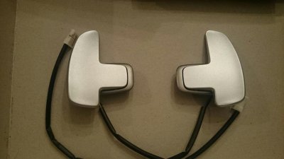
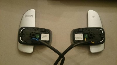
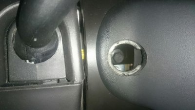
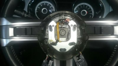
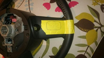
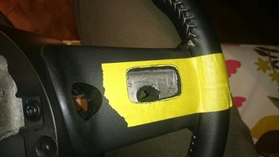
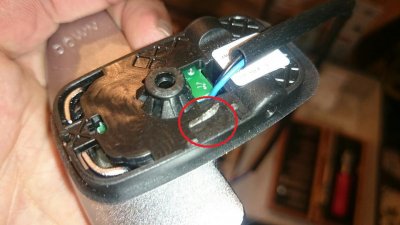
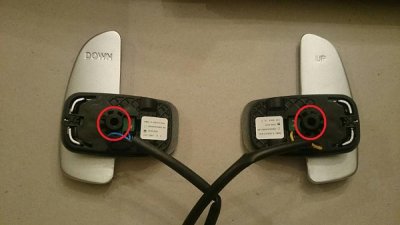
This is a How To thread on how to add the Mercedes AMG paddle shifters to the 2013/2014 Mustang automatic cars.

Note: this CAN be done to 2011/2012 cars. My car is a 2012. See the following thread to first get Sport Select Shift. Once you have that, you can do this mod.

http://themustangsource.com/forums/f...-autos-536398/

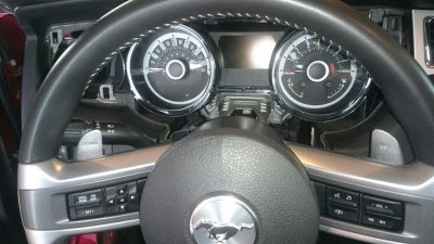
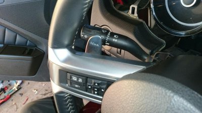
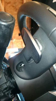
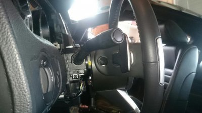
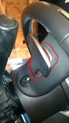
This is what the wheel will look like with the paddles:
 

Attachments

  • DSC_2313.jpg
    DSC_2313.jpg
    87.6 KB · Views: 30
  • DSC_2307.jpg
    DSC_2307.jpg
    127.2 KB · Views: 30
  • DSC_2308.jpg
    DSC_2308.jpg
    117.8 KB · Views: 31
  • DSC_2314.jpg
    DSC_2314.jpg
    63.4 KB · Views: 31
  • DSC_2278_1.jpg
    DSC_2278_1.jpg
    89.5 KB · Views: 31
  • DSC_2279.jpg
    DSC_2279.jpg
    88.8 KB · Views: 32

jim010

Junior Member
Joined
Sep 16, 2015
Posts
28
Reaction score
0
These paddle shifters are Mercedes AMG. There are many people out there using these for their cars. I have found threads showing How Tos for putting these on BMWs, Chargers/Challengers/300s, Focus and even Escapes. Why no one has tried a Mustang is beyond me. I guess I am the first.

If you mess anything up, I am not responsible. This is what I did to make this work. You may come up with something better. If so, please post it!

Here is what you need:

-Mercedes AMG paddle shifters - part number A 171 267 00 46 (I got mine from ECS Tuning)
-2 screws 8-32 in size
-2 hard rubber washers 3mm thick (I took mine from an old garden hose)
-2 metal washers at least 1 cm diameter
-hard foam sheet or abs plastic 3mm thick
-control module from TRS300 Custom Products website is below. You should go there and read up on his module. He is also VERY helpful with tech support!
http://lxcs.weebly.com/paddle-shifter-introduction.html
 

jim010

Junior Member
Joined
Sep 16, 2015
Posts
28
Reaction score
0
Disconnect the battery and wait 10 min, unless you always wondered what it is like to have an airbag explode in your face.

First to remove the steering wheel. On each side of the wheel will be a black plastic plug that you will need to pry off. That will expose the screws that hold the airbag in place. Take them out.

Now you can pull the airbag unit off. Unplug the 2 plugs on the back and remove the airbag.

Also, disconnect the plug for the clockspring located at the top of the wheel. You will also disconnect the left and right switches and remove both switches.

You will now see the main bolt holding on the steering wheel. Take it off and remove the wheel.
 

Attachments

  • DSC_2282.jpg
    DSC_2282.jpg
    64.6 KB · Views: 29
  • DSC_2285.jpg
    DSC_2285.jpg
    50.7 KB · Views: 23

jim010

Junior Member
Joined
Sep 16, 2015
Posts
28
Reaction score
0
Now that you have the wheel off, you will need to mark where the paddles will sit on the back of the wheel.

I placed masking tape on the back area. I also made an outline of the shape of the bottom of the paddle that will sit in the hole you are about to cut.

Find where you want that outline to sit and trace it onto the masking tape.

Measure three times, cut once! Make sure you have the paddle shifter outline exactly where you want it to sit!

You will now get an hobby knife (it is like a scalpel), or an exacto knife may be OK. I find I have a better time cutting precisely with the hobby knife, though.

Now cut all the way down to the metal and pull out the rubber.

Keep test fitting the paddle shifters as you trim out the perimeter.
 

Attachments

  • DSC_2291.jpg
    DSC_2291.jpg
    68.7 KB · Views: 24
  • DSC_2292.jpg
    DSC_2292.jpg
    90.8 KB · Views: 24

jim010

Junior Member
Joined
Sep 16, 2015
Posts
28
Reaction score
0
On the shifters, there is a plastic tap on the bottom that holds the wires in places. I broke them off as they seemed to interfere with how flush they will sit.
 

Attachments

  • DSC_2295.jpg
    DSC_2295.jpg
    65.1 KB · Views: 25

jim010

Junior Member
Joined
Sep 16, 2015
Posts
28
Reaction score
0
Now you will need to test fit the paddles and mark on the bare metal were the hole needs to be drilled to allow the paddles to be screwed onto the wheel.

You need a steady hand for this. I used a drill, but a dremel would be handy for this.

Drill a pilot hole first. Then go bigger and bigger as needed. The hole you drill will need to allow the seat for the screw on the paddle to poke in.
 

Attachments

  • DSC_2279 (1).jpg
    DSC_2279 (1).jpg
    64.9 KB · Views: 22

jim010

Junior Member
Joined
Sep 16, 2015
Posts
28
Reaction score
0
Now you may have noticed that the paddles can't sit perfectly flush and still have the paddles be able to be pressed.

There are 2 possibilities here. Use the dremel to drill out more of the steering wheel metal to allow the areas indicated on the bottom of the paddles to sit deeper into the wheel.
 

Attachments

  • DSC_22951.jpg
    DSC_22951.jpg
    68.3 KB · Views: 25

jim010

Junior Member
Joined
Sep 16, 2015
Posts
28
Reaction score
0
I did not have a dremel, so this was not something I was going to do with a drill.

Option 2 was to raise how the paddle shifter would sit by 3 mm.

To do this, I got some hard black sheet foam from the craft store and cut a trim piece that I would then use as a seat for the paddles.
 

Attachments

  • DSC_2304.jpg
    DSC_2304.jpg
    106 KB · Views: 22
  • DSC_2305.jpg
    DSC_2305.jpg
    121 KB · Views: 19
  • DSC_23081.jpg
    DSC_23081.jpg
    121 KB · Views: 25

jim010

Junior Member
Joined
Sep 16, 2015
Posts
28
Reaction score
0
Here is where I used the hard rubber washers. Since the paddles in my solution don't sit flat against the metal, the washers prevent the paddle from rocking around when pressing on them.
 

Attachments

  • DSC_2327.jpg
    DSC_2327.jpg
    74.9 KB · Views: 23

jim010

Junior Member
Joined
Sep 16, 2015
Posts
28
Reaction score
0
You will need to thread the holes in the paddles, as they are not threaded.

Be careful here that you don't strip the holes. If you do, then you will need to go up a width in screw size.

I had to cut down the length of my screws using a hack saw, as they were too long. You will probably need to do the same. Measure how deep the hole is, and how much extra you will need to allow the screw to come in from the inside of the wheel.

Line up the paddle and screw it in. Use a wide metal washer as in the pic. I also used a small washer as well, as my screw was slightly too long.

Again, careful not to strip the hole!
 

Attachments

  • DSC_2316.jpg
    DSC_2316.jpg
    48.4 KB · Views: 23

jim010

Junior Member
Joined
Sep 16, 2015
Posts
28
Reaction score
0
OK, the paddles are now in, and they will look great, but now you need to make them work.

The wire plugs on the paddles need to be removed (Do this before mounting the paddles, unlike me who was impatient). Gently pry/break the plastic plugs off leaving only the wire connectors.

Also, remove the horn plate. You will have better access. The screws are circled, as is the power wire.
 

Attachments

  • DSC_2317.jpg
    DSC_2317.jpg
    50.2 KB · Views: 24
  • DSC_2318.jpg
    DSC_2318.jpg
    61.9 KB · Views: 21
  • DSC_22851.jpg
    DSC_22851.jpg
    53.1 KB · Views: 22

jim010

Junior Member
Joined
Sep 16, 2015
Posts
28
Reaction score
0
Here is where Tim Stones' module that he made for the Chryslers comes in.

The transmitter module will go inside the wheel. You will plug in the paddles into the transmitter.

PU is paddle up
PD is paddle down
P- is for the black wires from the paddles. It doesn't matter which black wire goes on which P- pin.

The ground wire will go the the ground right in the wheel. I have it circled.
 

Attachments

  • DSC_2319.jpg
    DSC_2319.jpg
    60.5 KB · Views: 21
  • DSC_23201.jpg
    DSC_23201.jpg
    84.5 KB · Views: 23

jim010

Junior Member
Joined
Sep 16, 2015
Posts
28
Reaction score
0
This transmitter needs to have power. You will need to get it from somewhere else in the car. Luckily, there is an empty slot in the clockspring, which we will use.

The steering wheel clockspring pug is already unplugged. You will also unplug the one from the steering wheel column. Take off the red tabs on both the plugs to allow you to insert new female pins into those empty slots.

I used female pins from some old harnesses I have (And I have many), but you may need to go to an electronics store or repair shop to get yours.

Once you have the female pins, add wires to them. The red power wire from the transmitter will go to the empty slot on the steering wheel side. The one from the steering wheel column will have the other wire continue on.

You can now put the horn plate back on and tuck all the wires away. I tucked the transmitter in behind the horn plate and taped it up.
 

Attachments

  • DSC_2307_1.JPG
    DSC_2307_1.JPG
    88.4 KB · Views: 25
  • DSC_2308_1.JPG
    DSC_2308_1.JPG
    59.6 KB · Views: 21
  • DSC_2324.jpg
    DSC_2324.jpg
    70.3 KB · Views: 23
  • DSC_2325.jpg
    DSC_2325.jpg
    70.4 KB · Views: 23

jim010

Junior Member
Joined
Sep 16, 2015
Posts
28
Reaction score
0
Now for the receiver unit.

It has 4 wires coming form it, and you want to place the receiver close to the steering wheel as possible.

Yellow wire is for up shift.
Blue is for down shift.
Black is ground.
Red is power.

The power wire you routed through the clockspring I spliced into the red wire coming from the receiver.

I placed the receiver in a nook above the ignition cylinder barrel. It fits good and won't jostle around, but you can put it anywhere.
 

Attachments

  • ED58A696-6FCA-4284-902E-24C742F4347B_zps4dg58us3.jpg
    ED58A696-6FCA-4284-902E-24C742F4347B_zps4dg58us3.jpg
    49.8 KB · Views: 23
  • DSC_2306.jpg
    DSC_2306.jpg
    131.9 KB · Views: 20

jim010

Junior Member
Joined
Sep 16, 2015
Posts
28
Reaction score
0
Now route the 4 wires from the receiver down to the center console. You will need to remove the center console trim for this. All you do is open the console door at the back, find the edge of the trim and pull up on it. It is held in by clips only.

Look for the wires coming from the connector on the shifter box. You are looking for wires from slots 9, 10 and 11.

9 - shift up - brown
10 - shift down - green/purple
11 - signal return - green white

The wires you see in the pic are different colours because I added Sport Select Shift to my car. Remember that my car is a 2012. But I circled the connector plugs where you will find wires 9, 10 and 11. Those are the ones you want.

The wires from the receiver will splice into these.

Yellow from the receiver goes to wire 9 - brown
Blue from the receiver goes to wire 10 - green/purple
black can go to any ground, but I brought it back to the signal return wire 11 - green/white

The red wire is power. You need 12V power for this, and I took it from the 12V power socket in the center console. Tap into the red/grey wire from the socket.

When both transmitter and receiver have power, they have LEDs that will blink.

Put everything back together. You are done. Enjoy your paddle shifters!
 

Attachments

  • DSC_2315.jpg
    DSC_2315.jpg
    63.5 KB · Views: 19
  • DSC_2323.jpg
    DSC_2323.jpg
    69.7 KB · Views: 20

jim010

Junior Member
Joined
Sep 16, 2015
Posts
28
Reaction score
0
I see I did not post in the right spot. Can a moderator move this to the proper section? Maybe this is worth a sticky?
 

stkjock

---- Madmin ----
Staff member
Administrator
Super Moderator
S197 Team Member
Joined
Jul 10, 2007
Posts
40,242
Reaction score
3,157
Location
Long Island NY
It's in the right section already
 

Wes06

forum member
Joined
Jan 21, 2012
Posts
5,383
Reaction score
59
A newer guy posting in tech. And it's WORTHY?!?
What is going on here??? Lol
 

Support us!

Support Us - Become A Supporting Member Today!

Click Here For Details

Sponsor Links

Banner image
Back
Top