Post or link any and all info regarding cams. Discuss.
To start out. Some diagrams sourced from Comp.
Lobe Diagram
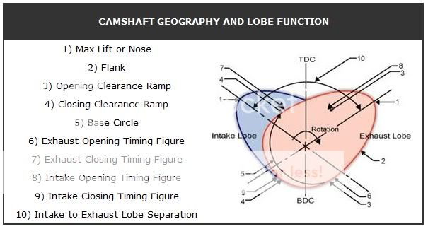
The terms:
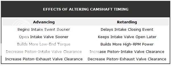
advance – Most commonly refers to combustion timing. Engine timing advance refers to crankshaft timing with regards to achieving piston Top Dead Center (TDC) prior to the combustion event within a cylinder. With regards to advance for camshaft timing – another meaning is the relationship of the intake centerline to TDC of the piston
area under the curve – Describes what a valve-lift cycle would look like if plotted on a graph with time in crank degrees running horizontally and valve lift in thousandths of an inch running vertically. The more quickly the valve opens and dwells in that position, the greater the space from opening to closing or beneath the curve.
cam button – A component that fits into the center of the timing gear and contacts the back of the timing chain cover to reduce the endplay of the camshaft. The cam button needs to be held in with a plate or have some way to keep it in place.
camshaft degreeing – The process of measuring the exact degree position of the camshaft relative to the combustion cycle. This allows for proper timing adjustment to tailor the performance characteristics of the engine.
closing ramp – The end of the valve-opening event, which defines how the valve is returned to the closed position.
coil bind – The point at which a valve spring can no longer be compressed and becomes a solid mass. Extreme valve train damage can occur at this point.
combustion event – The point in the engine cycle (either four or two) when the ignition is triggered, igniting the fuel/air mixture and driving the piston down within the cylinder.
compression – A mathematical calculation that takes into account bore, stroke and cc of the head, head gasket thickness and deck height to determine the static compression of the engine.
cylinder pressure – An engine uses compression to make engine power. Cylinder pressure is determined by camshaft duration, lobe separation and the static compression figures. Excessive cylinder pressure can lead to detonation and other engine problems.
deck height – The height of the cylinder block surface on which the cylinder head rests. Deck height is measured from the crankshaft centerline to the deck surface. It should be uniform from front to rear and may be corrected by machining if necessary.
duration – The amount of time the lobe is creating lift measured in degrees of camshaft rotation.
endplay – Refers to the movement of the camshaft forward and backward within the camshaft galley. Setting the proper amount of endplay is important to avoid excessive valve train wear and timing chain failure and ensure proper lifter positioning. Endplay can also create distributor spark fluctuations.
engine vacuum – The amount of vacuum generated by the engine within the intake manifold during combustion. Vacuum is altered by the camshaft duration specifications, chiefly as a result of overlap.
hot vs. cold valve lash setting – The lash setting is the mechanical camshaft setting that allows for a measurable distance between the rocker arm tip and valve stem. The cold setting is set before the engine has been operating and is larger than the hot lash setting, which is completed after the engine has achieved operating temperature.
intake centerline – The midpoint of the lobe (which may or may not be maximum lift, since some cams are asymmetrical in design).
installed height – The overall measurement of the valve spring when installed from the spring seat to the top of the retainer.
journal diameter – The cross sectional diameter of the cam bearing journal.
lift – The amount of travel by the lifter from the “zero location” on the camshaft up to the nose of the cam lobe. That measurement multiplied by the rocker arm ratio generates the total valve lift figure.
lifter preload – The initial pressure applied to the lifter most often through the rocker arm system.
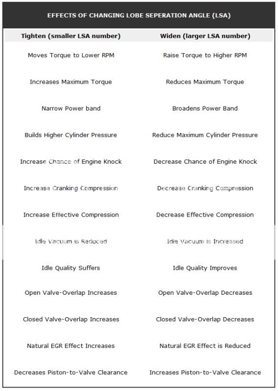
lobe separation angle – The number of degrees between the intake and exhaust lobe centerlines.
milling – The process of removing, with carbide cutters, a thin layer of metal from the surface of a head or block deck. This is done to restore the flatness of the surface and/or remove material for increased compression.
piston to valve clearance – The clearance between the valve and the piston when the two are at their closest point.
opening ramp – The section of the camshaft lobe between the base circle and the lobe peak.
open pressure – Spring pressure created when the valve is open. There needs to be enough pressure at this point to generate valve train control.
O.D and I.D. – Outside diameter and inside diameter measurements.
ramp speed (aggressiveness of lobe profile) – Refers to the ramp angle of the camshaft lobe. The more aggressive the lobe ramp, the faster the valve opens and closes.
retard – The opposite of the advance event; refers to something that occurs after the combustion event within the cylinder.
rocker arm ratio – The differential between the pushrod and valve stem side of the rocker axis point, expressed as a ratio.
seat pressure – The pressure most commonly in pounds per square inch – exerted on the spring seat. This can be during rest – when the valve is closed.
shim – A thin flat disc in varying thicknesses used to adjust (compress) the valve spring’s installed height.
single and dual pattern camshafts – When the intake and exhaust specifications (lift and duration) on the camshaft are the same, this is a single pattern camshaft. When the intake and exhaust specifications are different, this is a dual pattern camshaft.
symmetrical vs. asymmetrical lobes – When the opening and closing halves of the camshaft lobes are different, they are called asymmetrical lobes. Generally, the opening ramp is more aggressive on these lobes with a longer, slower closing ramp.
split duration camshaft – A camshaft where the intake and exhaust duration specifications are different.
Top Dead Center (TDC) – The highest point achieved by the piston travel within the cylinder bore.
valve float – The point at which the intake lifter and the camshaft lobe are not tracking at the same moment. This is an extremely dangerous event and can, in its most extreme condition, cause valve contact with the piston. Regardless, the peak engine efficiency is not present.
valve lash – A measurement taken between the tip of the valve stem and rocker arm tip. Valve lash is always measured with the lifter positioned off the lobe of the cam. This measurement is taken while adjusting a solid lifter valve train.
valve margin – The distance from the face of the valve straight up the side of the valve to the bottom edge of the valve seat.
valve overlap – This is a function of both duration and lobe separation angle. If the lobe separation angle remains the same but you increase the duration, the amount of overlap will also increase. Overlap is the time, measured in crankshaft degrees, when the exhaust valve and intake valves are both open.
valve train – Valve train is an all-encompassing term used to describe the mechanisms and parts that control the operation of the valves.
To start out. Some diagrams sourced from Comp.
Lobe Diagram
The terms:
advance – Most commonly refers to combustion timing. Engine timing advance refers to crankshaft timing with regards to achieving piston Top Dead Center (TDC) prior to the combustion event within a cylinder. With regards to advance for camshaft timing – another meaning is the relationship of the intake centerline to TDC of the piston
area under the curve – Describes what a valve-lift cycle would look like if plotted on a graph with time in crank degrees running horizontally and valve lift in thousandths of an inch running vertically. The more quickly the valve opens and dwells in that position, the greater the space from opening to closing or beneath the curve.
cam button – A component that fits into the center of the timing gear and contacts the back of the timing chain cover to reduce the endplay of the camshaft. The cam button needs to be held in with a plate or have some way to keep it in place.
camshaft degreeing – The process of measuring the exact degree position of the camshaft relative to the combustion cycle. This allows for proper timing adjustment to tailor the performance characteristics of the engine.
closing ramp – The end of the valve-opening event, which defines how the valve is returned to the closed position.
coil bind – The point at which a valve spring can no longer be compressed and becomes a solid mass. Extreme valve train damage can occur at this point.
combustion event – The point in the engine cycle (either four or two) when the ignition is triggered, igniting the fuel/air mixture and driving the piston down within the cylinder.
compression – A mathematical calculation that takes into account bore, stroke and cc of the head, head gasket thickness and deck height to determine the static compression of the engine.
cylinder pressure – An engine uses compression to make engine power. Cylinder pressure is determined by camshaft duration, lobe separation and the static compression figures. Excessive cylinder pressure can lead to detonation and other engine problems.
deck height – The height of the cylinder block surface on which the cylinder head rests. Deck height is measured from the crankshaft centerline to the deck surface. It should be uniform from front to rear and may be corrected by machining if necessary.
duration – The amount of time the lobe is creating lift measured in degrees of camshaft rotation.
endplay – Refers to the movement of the camshaft forward and backward within the camshaft galley. Setting the proper amount of endplay is important to avoid excessive valve train wear and timing chain failure and ensure proper lifter positioning. Endplay can also create distributor spark fluctuations.
engine vacuum – The amount of vacuum generated by the engine within the intake manifold during combustion. Vacuum is altered by the camshaft duration specifications, chiefly as a result of overlap.
hot vs. cold valve lash setting – The lash setting is the mechanical camshaft setting that allows for a measurable distance between the rocker arm tip and valve stem. The cold setting is set before the engine has been operating and is larger than the hot lash setting, which is completed after the engine has achieved operating temperature.
intake centerline – The midpoint of the lobe (which may or may not be maximum lift, since some cams are asymmetrical in design).
installed height – The overall measurement of the valve spring when installed from the spring seat to the top of the retainer.
journal diameter – The cross sectional diameter of the cam bearing journal.
lift – The amount of travel by the lifter from the “zero location” on the camshaft up to the nose of the cam lobe. That measurement multiplied by the rocker arm ratio generates the total valve lift figure.
lifter preload – The initial pressure applied to the lifter most often through the rocker arm system.
lobe separation angle – The number of degrees between the intake and exhaust lobe centerlines.
milling – The process of removing, with carbide cutters, a thin layer of metal from the surface of a head or block deck. This is done to restore the flatness of the surface and/or remove material for increased compression.
piston to valve clearance – The clearance between the valve and the piston when the two are at their closest point.
opening ramp – The section of the camshaft lobe between the base circle and the lobe peak.
open pressure – Spring pressure created when the valve is open. There needs to be enough pressure at this point to generate valve train control.
O.D and I.D. – Outside diameter and inside diameter measurements.
ramp speed (aggressiveness of lobe profile) – Refers to the ramp angle of the camshaft lobe. The more aggressive the lobe ramp, the faster the valve opens and closes.
retard – The opposite of the advance event; refers to something that occurs after the combustion event within the cylinder.
rocker arm ratio – The differential between the pushrod and valve stem side of the rocker axis point, expressed as a ratio.
seat pressure – The pressure most commonly in pounds per square inch – exerted on the spring seat. This can be during rest – when the valve is closed.
shim – A thin flat disc in varying thicknesses used to adjust (compress) the valve spring’s installed height.
single and dual pattern camshafts – When the intake and exhaust specifications (lift and duration) on the camshaft are the same, this is a single pattern camshaft. When the intake and exhaust specifications are different, this is a dual pattern camshaft.
symmetrical vs. asymmetrical lobes – When the opening and closing halves of the camshaft lobes are different, they are called asymmetrical lobes. Generally, the opening ramp is more aggressive on these lobes with a longer, slower closing ramp.
split duration camshaft – A camshaft where the intake and exhaust duration specifications are different.
Top Dead Center (TDC) – The highest point achieved by the piston travel within the cylinder bore.
valve float – The point at which the intake lifter and the camshaft lobe are not tracking at the same moment. This is an extremely dangerous event and can, in its most extreme condition, cause valve contact with the piston. Regardless, the peak engine efficiency is not present.
valve lash – A measurement taken between the tip of the valve stem and rocker arm tip. Valve lash is always measured with the lifter positioned off the lobe of the cam. This measurement is taken while adjusting a solid lifter valve train.
valve margin – The distance from the face of the valve straight up the side of the valve to the bottom edge of the valve seat.
valve overlap – This is a function of both duration and lobe separation angle. If the lobe separation angle remains the same but you increase the duration, the amount of overlap will also increase. Overlap is the time, measured in crankshaft degrees, when the exhaust valve and intake valves are both open.
valve train – Valve train is an all-encompassing term used to describe the mechanisms and parts that control the operation of the valves.
Last edited: