Jack Wallace

Junior Member
Joined
Jun 9, 2023
Posts
20
Reaction score
0
Location
Waco, TX
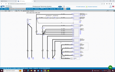
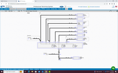
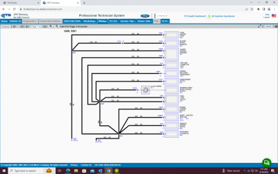
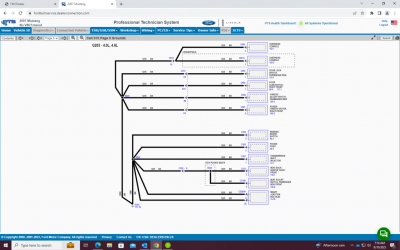
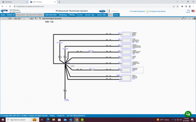
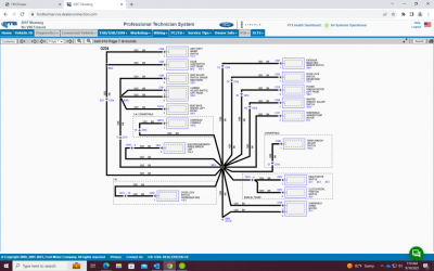
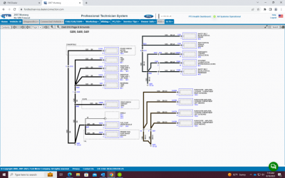
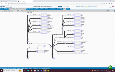
Hey guys! Currently in the process of restoring a 2007 Mustang GT. I’m redoing a lot of the factory wiring as some of it is damaged or just looks dingy and I’ve got a couple questions about the grounds. I’ve relocated the battery to the trunk, so I will be relocating all of the grounds (all 2, lol) that originally came off of the negative battery terminal when it was in the engine bay (don’t worry, I have grounded the negative terminal on the battery to a good location in the trunk). My current plan is to ground G106 (starter) and G107 (actually not sure where this goes, please tell me if you know) to the same location on either the body or frame (using 2 4AWG wires connected at the same location). I also need to figure out exactly where G102 and G103 were originally grounded so I can put them back in the right spot (I believe they may ground to the same location?). Will I have any issues doing this? If someone could tell me the exact locations of G102, G103, G106, and G107 that would be much appreciated.

Thanks!
 

86GT351

forum member
Joined
Nov 14, 2010
Posts
6,049
Reaction score
909
Location
Sunny South Florida
Hey guys! Currently in the process of restoring a 2007 Mustang GT. I’m redoing a lot of the factory wiring as some of it is damaged or just looks dingy and I’ve got a couple questions about the grounds. I’ve relocated the battery to the trunk, so I will be relocating all of the grounds (all 2, lol) that originally came off of the negative battery terminal when it was in the engine bay (don’t worry, I have grounded the negative terminal on the battery to a good location in the trunk). My current plan is to ground G106 (starter) and G107 (actually not sure where this goes, please tell me if you know) to the same location on either the body or frame (using 2 4AWG wires connected at the same location). I also need to figure out exactly where G102 and G103 were originally grounded so I can put them back in the right spot (I believe they may ground to the same location?). Will I have any issues doing this? If someone could tell me the exact locations of G102, G103, G106, and G107 that would be much appreciated.

Thanks!
Message me your VIN and I will see what I can get for you.
 

JC SSP

Senior Member
Joined
Nov 8, 2022
Posts
1,084
Reaction score
468
Location
FL
Good info for a sticky... maybe under wiring schematics?
 

Jack Wallace

Junior Member
Joined
Jun 9, 2023
Posts
20
Reaction score
0
Location
Waco, TX
Thanks for the info, as this is relatively helpful. However, I already know where the grounds are supposed to go on the battery and PCM side, and am wondering where the physically ground to (what bolt, what part of the frame, where on the starter/engine/etc.). This may require some actual pictures from an engine bay, but I’m not sure. Or perhaps there is a way to deduce that from the wiring diagram? Just let me know!
 

Samos3

Member
Joined
Feb 27, 2022
Posts
163
Reaction score
87
Location
St. Louis
As you look thru that link, look for Wiring Diagrams, then choose Ground Location Index. It's not drawings, but it does describe the ground locations and gives their code number to match to the wiring diagrams.
 

Jack Wallace

Junior Member
Joined
Jun 9, 2023
Posts
20
Reaction score
0
Location
Waco, TX
As you look thru that link, look for Wiring Diagrams, then choose Ground Location Index. It's not drawings, but it does describe the ground locations and gives their code number to match to the wiring diagrams.
Gotcha, I've figured a good bit more out now. The current plan (battery is in trunk):
Positive side:
- Cable from positive battery terminal to 4 stud power distribution block in engine bay
- stud 2 will have power cable to fuse box
- stud 3 will have power cable to starter
- stud 4 will have power to alternator
Negative side:
- wire will be run from negative battery terminal in trunk to engine bay where it will be ground on the frame to prevent any voltage drops that could resort from it being grounded in the trunk
- G107 (strut tower ground) will be connected directly to G106 (ground on passenger motor mount)...these were both originally connected to negative terminal on battery

Remaining questions:
Will I have any issues now that the battery will not be directly grounded to the engine itself?
I want to avoid redundant grounds and unnecessary wires, so let me know if there's anything I can eliminate.
Most importantly, I don't want to have any electrical issues, so let me know if there is something I can add.

Thanks guys.
 

Samos3

Member
Joined
Feb 27, 2022
Posts
163
Reaction score
87
Location
St. Louis
Well, consider that the engine is effectively the ground connection for the sparkplugs. A direct ground from the engine to the battery is a good way to make sure the ignition system is operating as best it can. This is possibly important for the FI as it relies on the coolant temp sensor. I say 'possibly' because I have not dived into the in's and out's (pun intended!) of the electrical path for this car. On older cars (FI and carb) the sensor signals grounded thru the block and did not have a separate return path thru the wiring harness.
 

moooosestang

Member
Joined
Nov 27, 2022
Posts
261
Reaction score
95
Location
Alachua, fl
Gotcha, I've figured a good bit more out now. The current plan (battery is in trunk):
Positive side:
- Cable from positive battery terminal to 4 stud power distribution block in engine bay
- stud 2 will have power cable to fuse box
- stud 3 will have power cable to starter
- stud 4 will have power to alternator
Negative side:
- wire will be run from negative battery terminal in trunk to engine bay where it will be ground on the frame to prevent any voltage drops that could resort from it being grounded in the trunk
- G107 (strut tower ground) will be connected directly to G106 (ground on passenger motor mount)...these were both originally connected to negative terminal on battery

Remaining questions:
Will I have any issues now that the battery will not be directly grounded to the engine itself?
I want to avoid redundant grounds and unnecessary wires, so let me know if there's anything I can eliminate.
Most importantly, I don't want to have any electrical issues, so let me know if there is something I can add.

Thanks guys.

There is zero reason to run a ground all the way back to the engine bay unless you need to add a battery disconnect for racing. one of the threaded holes in the trunk floor works just fine. The battery ground should be as short as possible. There's a ground off the back of the drivers side head that goes to the firewall, there's a ground that connects to the passenger side motor mount then runs to the passenger side strut tower i believe where the original battery ground connected.

battery1.jpg
 

DieHarder

Senior Member
Joined
Nov 9, 2019
Posts
1,468
Reaction score
758
Agree with above. However, to ensure maximum output from the alternator I would add a ground from the body of the alternator and run it to the ground on the passenger strut tower. This will ensure the ground potential at the alternator is the same as the chassis ground.
 

moooosestang

Member
Joined
Nov 27, 2022
Posts
261
Reaction score
95
Location
Alachua, fl
I also added a ground from the motor mount to a hole on the frame rail that was for one of those plastic wire loom holders for the starter cable just because i ran a larger gauge + wire to my starter and wanted the same size ground going to the motor. i'll take a pic tomorrow. you can't have too many grounds imo, but you want them short as possible.
 

Jack Wallace

Junior Member
Joined
Jun 9, 2023
Posts
20
Reaction score
0
Location
Waco, TX
Very good input from all of you guys here, thank you! So I think what I've determined is I'll leave the battery grounded to the body in the trunk, and I'll run an additional ground from alternator body to the passenger strut tower. I'll leave the ground running from the motor mount to the passenger strut tower as well. Without running a very long ground from battery in trunk to engine, I won't be able to ground the battery directly to the engine... will this be an issue?

Thanks again guys.
 

TexasBlownV8

Formerly TexasBlownV6
Joined
Apr 4, 2008
Posts
4,973
Reaction score
54
Location
Central Texas
I recently did a lot of this same stuff as part of battery and BEC relocation.
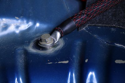
As shown above, I secured the ground in the trunk to one of the existing threaded bungs in the back to the left of the right side tailight, using a bolt that threads all the way through and then secures with a nut from underneath as well, cleaning the paint off all surfaces. Good, solid, ground to the frame.
For engine, the OEM ground connects to one of the two motor mount bracket studs on the passenger side (at least on my '09 engine, two of the 4 bolts are studs). I connected a new 2 ga. cable from one of the studs to the body nearby/at the frame, secured with bolt and lockwsher and nut. Very good ground.
Also was careful as part of my engine harness changes to properly ground things together near this as well, to another ground bolt, so that signal grounds are all close together.
I did not 'ground' the alternator separately as it is already secured solidly to the block and grounded that way.
I left the driver-side head ground strap as-is and in place for now, but might upgrade that as well and secure to a better location. In the meantime, that strap is in stock location to the body instead of to the frame.
 

DieHarder

Senior Member
Joined
Nov 9, 2019
Posts
1,468
Reaction score
758
Very good input from all of you guys here, thank you! So I think what I've determined is I'll leave the battery grounded to the body in the trunk, and I'll run an additional ground from alternator body to the passenger strut tower. I'll leave the ground running from the motor mount to the passenger strut tower as well. Without running a very long ground from battery in trunk to engine, I won't be able to ground the battery directly to the engine... will this be an issue?

Thanks again guys.

Good plan. No need to run a line from neg batt terminal all the way to engine ground. Ground potential at any point on the body should be the same throughout. What's important is ensuring output voltage from the alternator (and across the battery terminals) is in the normal range (14.3 - 14.7v). If not you need to figure out where the voltage is dropping. In my experience the most likely place is the engine (it's aluminum and presents a slight conductance difference; the two engine grounds are supposed to take care of that but don't always). Hence the reason I recommend adding a ground from the alternator body to the passenger strut tower.

For anyone: To test whether you might need to work on the grounds (or add a ground from the alternator to the passenger strut tower) simply put a VOM on volts DC and put one lead on the body of the alternator and the other on the passenger strut tower ground (engine running). If you read voltage that means there is a difference in the ground potential that the engine ground is at vs. the body ground. (In my case I had a ~1v voltage drop (about 13.4v across the battery terminals). The difference in resistance (due to materials/ corrosion/etc) results in a lower voltage output from the alternator compared to when those grounds (body & engine) are at the same potential. After adding an additional ground (4 gauge wire) from the alternator body to the passenger strut tower the voltage out of my alternator went up to 14.5v (across battery terminals). The alternator itself didn't change in any way; the ground potential at the body of the alternator did.
 
Last edited:

Support us!

Support Us - Become A Supporting Member Today!

Click Here For Details

Sponsor Links

Banner image
Back
Top