Torque arm and Watts Link added...

rwleonard

Junior Member
Joined
Feb 1, 2018
Posts
22
Reaction score
8
Location
Virginia
Had a Griggs TA installed last Monday and a BMR Watts Link installed last Friday on my 2013 GT500. I have not made it to the track yet, but the torque arm has made a huge difference even just driving around town. For example, when stopped on a hill, waiting for an opening to turn right into traffic, there was a pretty narrow window between stalling and wheel spin. That window is MUCH wider now, any reasonable throttle input just bites and goes. When it does slide, it is much more predictable and easier to control. As to the watts link, there are some bridge expansion joints on a long, sweeping curve that used to make the rear end really nervous, but those joints just soak right in now, without drama.

There is not doubt in my mind the TA will make the car easier to drive faster, and more importantly, more fun to drive on the track. I don't know if the WL will make me faster, but it certainly makes the car more enjoyable to drive, and that will do. I am just trying to have fun, after all.​

I picked up a noticeable amount of NVH with the torque arm. I have the rod end WL, and I can't tell that I picked up any NVH at all with it.

FWIW,

Rick
 

b.mad

Member
Official Vendor
Joined
Jun 6, 2016
Posts
94
Reaction score
6
The Torque is easily one of the biggest things you can do to the rear end of any SRA Mustang. It makes an incredible difference at the track.

There are tons of debates between the PHB and WL. For the most part, lots of designers prefer the WL because it is an even side to side movement versus the PHB favors one side over the other. However, there are some like Maximum Motorsports and Mike Maier who prefer the PHB. I run a PHB on my SN95 (and the S197 is factory). I can give a lot of other drivers a run for their money (even the ones running WL).

But, you will notice more of a difference with the TA than the WL, but together, it will feel like a whole new damn car!
 
Last edited:

kerrynzl

forum member
Joined
May 31, 2017
Posts
116
Reaction score
19
Location
Tauranga, New Zealand
I cannot figure out how those torque arms can work properly without binding. There is a long torque arm that pivots at the front, and 2 shorter trailing links at the outer axle tubes.
They both move on different Arcs so they will bind.

The torque arm is a piss poor application for a S197 , and during acceleration tries to thrust downwards at the front pivot. [not lift due to pinion torque reaction]

The watts link is not a total waste off money, but the panhard always gets blamed for unstability over bumps.
The real culprit is the trailing links moving on an arc causing the rear axle to steer going over bumps. The trailing links also cause roll steer.

Careful adjustments of the geometry would yield far greater gains, than a bolt-on POS that a manufacturer claims as the best thing since "sliced bread"

On a 3rd Gen Camaro the torque arm is better because it floats forward/aft at the front pivot AND the placement of the outer trailing links at the Axle centreline to control thrust [by this alone, all pinion torque reaction and brake torque is controlled by the TA]

On a S197the outer trailing links are pivoting below the Axle centreline, so axle thrust over weight resistance tries to nose the pinion downwards. A 3rd link above the rearend shares these loads and transfers the thrust into the frame [as acceleration]

Axle thrust is far greater than pinion torque reaction due to mechanical gearing [C & P ratio]
 

rwleonard

Junior Member
Joined
Feb 1, 2018
Posts
22
Reaction score
8
Location
Virginia
"I cannot figure out how those torque arms can work properly without binding."

Good thing Bruce Griggs has already figured that out for us!
 

Norm Peterson

corner barstool sitter
Joined
Feb 5, 2011
Posts
3,615
Reaction score
316
Location
RIP - You will be missed
I cannot figure out how those torque arms can work properly without binding. There is a long torque arm that pivots at the front, and 2 shorter trailing links at the outer axle tubes.
They both move on different Arcs so they will bind.
Obviously he's counting on there being enough compliance in the chassis-side bushings to accommodate plunge and rotations.

I agree; a 3rd gen Camaro-inspired design would probably have been a better solution.


The torque arm is a piss poor application for a S197 , and during acceleration tries to thrust downwards at the front pivot.
Ummm . . . no.


On a S197the outer trailing links are pivoting below the Axle centreline, so axle thrust over weight resistance tries to nose the pinion downwards. A 3rd link above the rearend shares these loads and transfers the thrust into the frame [as acceleration]
There are two ways to model what's going on. Either with some amount of traction force at the ground resolved into forward forces at the LCAs and a rearward force at the UCA to balance the force equation, or the same tractive force at the axle centerline plus the total axle torque reaction needed to generate that tractive force. In the latter case, you would compute as intermediate results forward forces on all three links from the force plus forward forces at the LCAs and a rearward force at the UCA from the required moment.

FWIW, in reasonably normal geometries, the magnitude of the force in the UCA isn't all that much different from the force in either LCA. Just tensile under acceleration where the LCA forces are compressive.

Axle thrust is far greater than pinion torque reaction due to mechanical gearing [C & P ratio]
At the UCA, the moment effect is bigger than the force effect. Has to be, unless maybe there's a way to locate the LCAs below the pavement. Crown & Pinion ratio has nothing to do with the proportion of axle torque to traction force or the distribution of the reaction forces.


Norm
 

b.mad

Member
Official Vendor
Joined
Jun 6, 2016
Posts
94
Reaction score
6
In order to understand the torque arm, you have to understand what it is replacing. The FAQ posted by Maximum Motorsports apply to 1979-04 Mustang, however, the geometries are almost the same as the S197. The difference being that the Fox/SN95 come with a 4-link, and the S197 comes with a 3-link, aka the poor mans 3-link: one UCA, 2 LCA, and an axle locator.

The differences are the TA replaces the UCA, and operations on a different motion.

And the 3rd Camaro has a different geometry than the S197. Requires different packaging. I dont see one being made for the S197s.

If you are still not convinced, call Mike Maier. But you better set aside a couple hours to check about Geometry. THIS DUDE CAN TALK. In person and on the phone, every conversation I've had with him easily turned into a 2 hour conversation.
 

Norm Peterson

corner barstool sitter
Joined
Feb 5, 2011
Posts
3,615
Reaction score
316
Location
RIP - You will be missed
GM's 3rd gen TA isn't basically any different than any other TA that's picked up on the chassis side through a compliant bushing. GM did have the advantage of being able to redesign the pumpkin to allow the TA as a (structurally correct) channel shape to be bolted up to the pinion snout instead of requiring additional structure to get 'round to the back side to use some of the diff cover bolts in order to develop enough bending moment strength at the axle end of the TA's beam.

I've put together Excel spreadsheet models of both the 3-link and the torque arm, and in the process found out that the approach to putting the TA's geometric construction together is surprisingly similar to that for the 3-link. Where the 3-link has a short more or less vertical element and a longer more or less horizontal link, the TA has a long horizontal beam and a more or less vertical link. In the case of a bushed TA chassis attachment, this more or less vertical link is virtual. Not physically present but defined by the TA's geometric construction. Kind of like a 3-link rotated 90° in side view with the lengths interchanged, if that makes sense.

The PM3L is a Fox/SN95 oddity caused by the remaining UCA still being skewed in plan view.


Norm
 

b.mad

Member
Official Vendor
Joined
Jun 6, 2016
Posts
94
Reaction score
6
GM's 3rd gen TA isn't basically any different than any other TA that's picked up on the chassis side through a compliant bushing. GM did have the advantage of being able to redesign the pumpkin to allow the TA as a (structurally correct) channel shape to be bolted up to the pinion snout instead of requiring additional structure to get 'round to the back side to use some of the diff cover bolts in order to develop enough bending moment strength at the axle end of the TA's beam.

Norm

Basically what I meant/said but you went more in depth lol

I've put together Excel spreadsheet models of both the 3-link and the torque arm, and in the process found out that the approach to putting the TA's geometric construction together is surprisingly similar to that for the 3-link. Where the 3-link has a short more or less vertical element and a longer more or less horizontal link, the TA has a long horizontal beam and a more or less vertical link. In the case of a bushed TA chassis attachment, this more or less vertical link is virtual. Not physically present but defined by the TA's geometric construction. Kind of like a 3-link rotated 90° in side view with the lengths interchanged, if that makes sense.

Norm

The TA is a 3-link technically, which is why the geometry is similar. But the difference being the horizontal beam vs the single control arm. As you mentioned.

The PM3L is a Fox/SN95 oddity caused by the remaining UCA still being skewed in plan view.


Norm

Yes. Which is basically what the stock rear suspension on the S197 is. Single UCA (1 link), and 2 LCA (2 links). And the PHB for axle locator. The difference is the Fox/SN95 rear suspension had 2 UCA (Hence the 4-link), and each UCA was attached from one side of the axle to a torque reinforcement. Versus the S197 is a single UCA in the middle.


My comment was directed towards kerrynzl, who is skeptical of the purpose of the TA but does not seem to understand its function. Hence why I suggested calling Mike Maier to chat. :)
 

kerrynzl

forum member
Joined
May 31, 2017
Posts
116
Reaction score
19
Location
Tauranga, New Zealand
The TA is a 3-link technically, which is why the geometry is similar. But the difference being the horizontal beam vs the single control arm. As you mentioned.

NO IT IS NOT, the 3 link pivots at the upper rear which makes a huge difference.
For every FT/LB of torque applied at the tyre footprint equals the same amount of thrust at the axle centreline.
This thrust needs to be transferred into the frame to accelerate the car[which is what a 3 link or 4 link does]
The 3 link [when viewed from the side] has an Instant centre which is the theoretical point of acceleration. [the same goes for the 4 link, the thrust is shared between the upper and lower links]
When pinion torque reaction is factored into the equation, the compression loads are less on the upper and increased on the lower links .Which is why a single upper is more than enough.

What GM did with the 3rd gen is place the Links directly in front of the axle centreline so it controls All the thrust loads. These links pivot so any rotational torque is controlled by the torque arm [the torque arm doesn't control any thrust loads at the front pivot, only vertical loads]

The MK1 Lotus Cortina is similar to the GM 3rd Gen by having the outer Links directly in front of the axle centreline, but instead of a Torque arm they had a Triangulated link under the diff housing [not needing a panhard or watts]
Lotus calculated that brake torque through the axle was far greater than pinion torque reaction so having the A Frame underneath was under tension during braking and stronger [Plus the roll centre was lower]

With the griggs TA with a fixed front pivot, [pivoting on a longer arc] it would be better off with the outer links removed[that pivot on a shorter arc] and then add 2 triangulated arms from the front pivot back to the outer axle tubes [truck arm style]


My comment was directed towards kerrynzl, who is skeptical of the purpose of the TA but does not seem to understand its function. Hence why I suggested calling Mike Maier to chat. :)

The reason I'm sceptical, Is I fully understand how a Torque Arm functions [I've designed and fabricated racecar suspension before] I don't really need to spend hours making an international phone call to listen to somebody justifying their opinion.
 

rwleonard

Junior Member
Joined
Feb 1, 2018
Posts
22
Reaction score
8
Location
Virginia
The TA has done exactly what Griggs said it would. Arguments to the contrary would require me to ignore my direct experience in order to believe them, and that would be a silly thing to do.
 

Norm Peterson

corner barstool sitter
Joined
Feb 5, 2011
Posts
3,615
Reaction score
316
Location
RIP - You will be missed
NO IT IS NOT, the 3 link pivots at the upper rear which makes a huge difference.
You missed the point I was trying to make. Once you consider the TA's beam to be no different from a diff housing with an extremely long pinion snout, and that no different from a 3rd link eye at the top of the diff housing, the geometry constructions are more similar than they are different. And it's the geometry that locates the SVIC, which in turn defines the geometric portion of load transfer.


For every FT/LB of torque applied at the tyre footprint equals the same amount of thrust at the axle centreline.
This thrust needs to be transferred into the frame to accelerate the car[which is what a 3 link or 4 link does]
It's what any suspension linkage for a driven axle has to do . . .


The 3 link [when viewed from the side] has an Instant centre which is the theoretical point of acceleration. [the same goes for the 4 link, the thrust is shared between the upper and lower links]
When pinion torque reaction is factored into the equation, the compression loads are less on the upper and increased on the lower links .Which is why a single upper is more than enough.
The single upper goes tensile. But yes, a single upper is sufficient. In most cases, the tensile load on the upper is of generally similar magnitude to the compressive load on either lower (taken individually).


What GM did with the 3rd gen is place the Links directly in front of the axle centreline so it controls All the thrust loads. These links pivot so any rotational torque is controlled by the torque arm [the torque arm doesn't control any thrust loads at the front pivot, only vertical loads]
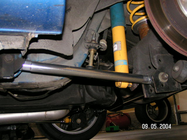
Actually the LCAs on the 3rd and 4th gen F-bodies picked up below the axle much like they do on the S197. This picture is from a 4th gen, but I have a 9-bolt axle holding up the back end of some non-GM car that I'm certain came out of a 3rd gen that picks up the LCAs in the same place (didn't the 9-bolt come from your part of the globe?).


LeftLCAOutbd.JPG


The MK1 Lotus Cortina is similar to the GM 3rd Gen by having the outer Links directly in front of the axle centreline, but instead of a Torque arm they had a Triangulated link under the diff housing [not needing a panhard or watts]
Lotus calculated that brake torque through the axle was far greater than pinion torque reaction so having the A Frame underneath was under tension during braking and stronger [Plus the roll centre was lower]
Directly in front of the axle would be a unique case. Meaning that you can't use a mathematical singularity like that to prove the general case. The wishbone would have to run backward from the axle in order to be in tension during forward acceleration. Keep in mind that the axle torque reaction is trying to make the pinion go nose up, so a forward-running wishbone would still have to go compressive to push it back down. Remember, it's not the LCAs trying to pull the pinion into a nose-up condition.

FWIW, I've seen pictures of this arrangement on fairly high-HP cars. Ground clearance, diff housing strength, and single-shear use of that big bolt would be direct design concerns. Exhaust routing and tube size would likely be affected.


With the griggs TA with a fixed front pivot, [pivoting on a longer arc] it would be better off with the outer links removed[that pivot on a shorter arc] and then add 2 triangulated arms from the front pivot back to the outer axle tubes [truck arm style]
The Griggs has to use a compliant front pivot, else the suspension becomes over-constrained and will bind. Like you said, if the Griggs TA front pivot was truly fixed, they might as well do their own version of Hotrods to Hell's truckarm.


The reason I'm sceptical, Is I fully understand how a Torque Arm functions [I've designed and fabricated racecar suspension before] I don't really need to spend hours making an international phone call to listen to somebody justifying their opinion.
All you need to do is accept the idea that Griggs incorporated enough compliance in their TA's front pivot design to accommodate plunge and rotations. It's the only way it can work without bending and fatigue-failing the brackets and other structure. I realize that taking out as much compliance as possible is the general approach to race car suspension design, but you simply can't do that with the Griggs TA design. (well, I suppose you could if you made the LCA bushings even softer than OE, but that'd be an even worse way to avoid 'bind'). Griggs can get away with this compliance because it doesn't affect axle steer enough to matter, and pinion angle only a little (due to the length of the TA).


Norm
 
Last edited:

b.mad

Member
Official Vendor
Joined
Jun 6, 2016
Posts
94
Reaction score
6
The reason I'm sceptical, Is I fully understand how a Torque Arm functions [I've designed and fabricated racecar suspension before] I don't really need to spend hours making an international phone call to listen to somebody justifying their opinion.

Didnt see that you were in New Zealand! That would have been expensive


But it seems that you are very stuck on your belief that the TA is not superior, despite the engineering and proven benefits behind it. If you are arguing the cost is not worth it, then I can partially agree. But I will not agree that a triangular system (which uses 2 uca (which are doing two jobs and cause binding) and 2 lca) is superior to a TA and axle locator, which separates the job of the UCA's into 2 different components.
 
Last edited:

Norm Peterson

corner barstool sitter
Joined
Feb 5, 2011
Posts
3,615
Reaction score
316
Location
RIP - You will be missed
Just to be clear, the OE 3rd gen LCA attachment holes are the uppermost ones in that picture; weld-on LCA relo brackets were added by the owner.


Norm
 

Norm Peterson

corner barstool sitter
Joined
Feb 5, 2011
Posts
3,615
Reaction score
316
Location
RIP - You will be missed
Truth is, a properly designed/engineered TA-equipped car is easy to get into and drive hard. Even the first time.

The one time I've driven such a car (an ESP-level 4th gen Firebird) was at autocross, and I was running in the same second as its owner (not an autocross newbie). Not just my first time driving such a car, either; it was also the first time I'd ever run on R-compound tires.


Norm
 

rwleonard

Junior Member
Joined
Feb 1, 2018
Posts
22
Reaction score
8
Location
Virginia
Careful Norm. It sounds like you are pretty close to committing the logical error of believing what you have actually experienced over what you read on an internet car forum.
 

kerrynzl

forum member
Joined
May 31, 2017
Posts
116
Reaction score
19
Location
Tauranga, New Zealand
The single upper goes tensile. But yes, a single upper is sufficient. In most cases, the tensile load on the upper is of generally similar magnitude to the compressive load on either lower (taken individually).


Norm

The only way to get the single upper control arm into tension is to remove axle thrust from the equation.
Dirt modifieds do this by floating the axle tubes with birdcages [and 4 links]
They also use torque arms with birdcages successfully.

With 3 links and 4 links all of them are subject to compression loads during acceleration unless the lower links are at the axle centreline [or close to it]

People seem to think that there is this overwhelming "wheelstanding" force coming from a torque arm. But pinion torque reaction is small when compared to the compression loads caused by axle thrust.


By the way I crawled under my Mustang and measured the LCA [they are sitting 2" lower at the front] With 2" of suspension travel the Arm arcs 0.340"
So If we had a Torque Arm that pivoted up by the shifter it would be 57.5"long to the axle centreline.
A 57.5" Arm would only arc 0.030" for the same 2" of suspension travel.

Having a 57.5" long TA and two 18" long links would need 0.310" of compliance in the bushing [on a race car part ?? ]

Needing 0.310" compliance would cause the suspension to bind , the reason the OP admitted to increased Noise/vibration/harshness


by the way everybody...... keep the arguments coming. this whole 'corner carver' section was slowly dying
 

Norm Peterson

corner barstool sitter
Joined
Feb 5, 2011
Posts
3,615
Reaction score
316
Location
RIP - You will be missed
The only way to get the single upper control arm into tension is to remove axle thrust from the equation.
Nope.

I may have drawn the free-body diagram for this, and I'll post it if I can find it. If not, maybe I'll redraw it. It's a simple beam analysis when you look at it in side view except that it doesn't look like any structural textbook sketch. I spent over 40 of the last 50 years learning about and getting paid to do that sort of thing.


Dirt modifieds do this by floating the axle tubes with birdcages [and 4 links]
A birdcage is a much different approach - they cannot resist axle torque so you have to add something that does. Dirt modified suspensions can be quite a bit more complex, as you can decouple squat reactions from rise (under braking) reactions as well.


People seem to think that there is this overwhelming "wheelstanding" force coming from a torque arm. But pinion torque reaction is small when compared to the compression loads caused by axle thrust.
Pinion torque reaction magnitude depends on its length, short TAs providing more force at the chassis-side pickup than longer ones. This is one reason why it's a good idea to keep the SVIC in mind and apply your horizontal and vertical forces at that location. A TA's SVIC can only lie at its chassis-side pickup if the LCAs aim directly at it (in side view).


By the way I crawled under my Mustang and measured the LCA [they are sitting 2" lower at the front] With 2" of suspension travel the Arm arcs 0.340"
So If we had a Torque Arm that pivoted up by the shifter it would be 57.5"long to the axle centreline.
A 57.5" Arm would only arc 0.030" for the same 2" of suspension travel.
I think that geometry puts the SVIC below grade even before considering 2" suspension bump travel. Very close to grade if it isn't. There's bound to be a better LCA inclination for use with a TA, so you wouldn't use it in the first place.


Having a 57.5" long TA and two 18" long links would need 0.310" of compliance in the bushing [on a race car part ?? ]
Compliance isn't always wrong, even in a race car. But it has to be done properly.


Needing 0.310" compliance would cause the suspension to bind , the reason the OP admitted to increased Noise/vibration/harshness
Needing that much compliance is a big reason why you wouldn't use that kind of TA pickup. Cutting 1" out of your 2" LCA slope brings that 2" bump compliance requirement down to just over 0.19". Taking all 2" out brings it down to about 1/8".

FWIW, I agree that it's causing increased NVH. If the bushing could be made softer in the fore/aft direction without compromising strength or durability, the amount of NVH would very likely be reduced.


Incidentally, the kinds of TAs that use a physical link at the chassis side seem to be very sensitive to their geometries when used in drag racing applications (big power, big grip).


Norm
 
Last edited:

stevbd

forum member
Joined
Jun 24, 2016
Posts
151
Reaction score
26
Two things seem to be true about watts link posts: 1) everyone who installs one says the rear axle is more settled over bumpy roads compared to a PHB, and 2) no one seems able to explain why that is from an engineering perspective. Some may claim confirmation bias but I kind of doubt it since I've never seen a post where someone installed a WL and did not notice this improvement.

I try not to buy stuff without at least a basic understanding of why it works but I might make an exception here. And yes, I do understand the other engineering advantages of a WL, but I don't get why it seems to ride better on bumpy surfaces.
 

Support us!

Support Us - Become A Supporting Member Today!

Click Here For Details

Sponsor Links

Banner image
Back
Top