Idle issues with lito tune..still :/

GlassTop09

Senior Member
Joined
May 24, 2019
Posts
1,142
Reaction score
525
Location
Farmington, NM
The problem Midlife Crises is describing is when the engine is coming from higher RPM's when the throttle body plates are fully closed (deceleration). The PCV valve located inside the driver side valve cover is a plunger w\ a specific sized orifice drilled in it's seat that is metering the amount of air to allow thru the PCV valve when the intake goes into high vacuum & the PCV plunger is drawn onto it's seat to "restrict" this airflow thru the crankcase. This amount of airflow will change due to the amount of deltaP (pressure drop) across the PCV orifice so the PCM will be trying to compensate for the rest of the airflow trying to control the engine idle, thus the throttle idle hunt.
In the initial instance the PCM has shut down the fuel injectors when it sees the TB has closed thru the TPS sensor so no fuel is injected so the engine slows down due to no power created from fuel burn AND from engine compression of the air. The issue starts happening around the 1,000 RPM area where the PCM will return the fuel injectors back to operation. The PCM sees the VSS & ABS wheel speed sensors still reporting vehicle movement & the higher MAF readings from air movement so injects fuel to match but the throttle plates are closed. The engine doesn't care so it's making power so until the airflow reduces thru the MAF & the VSS/ABS wheel speed sensors report no vehicle movement so then the PCM will pull the TB to full close AND cut injected fuel volume which will tend to drop the RPM's momentarily below the set idle RPM's then the PCM will reset the TB plates to reestablish the engine idle RPM's back to normal.
If any part is changed that will change fine airflow control around idle (specifically a larger sized TB, not so much the cams or intake manifold or exhaust upgrades....this is the only real advantage a smaller ported TB has over a larger one) it will make this harder to control thru the tune as the amount of air entering the intake manifold thru the PCV system during deceleration is unaccounted for vs the amount of air entering thru the closed TB plates so the PCM is trying to account for it thru TB movement thus idle hunt. The way that MC is rectifying this is to install a check valve in PS PCV inlet line w\ flow pointed towards the CAI inlet so when the engine goes into deceleration (high manifold vacuum) the check valve will close forcing the bulk of airflow after CAI MAF to go thru the TB instead of bypassing it thru the PCV system so the MAF signal will now fully correspond to the TB control so the amount of fuel injected will also correspond so the engine will slow to idle normally on a closed TB regardless of the VSS\ABS wheel speed sensors showing vehicle movement due to the lower engine power output.

The only issue that I have w\ using a check valve this way is you're taking a big chance on creating damage to the crankshaft rear main & harmonic balancer & other engine seals due to potential excess negative pressure in the crankcase causing 1. oil leaks & 2. the same issue of outside air entering around the MAF thru any seals whether leaking or not. These seals along w\ others are designed to operate in neutral crankcase pressure (or atmospheric pressure if you prefer) to facilitate the seals working as intended so no oil leaks out AND no outside air enters the intake tract around the MAF, thus another need for a PCV system to be fully functional. Excessive positive CC pressure will blow seals out, excess negative CC pressure can cause debris to be drawn into the seals cutting them.

IMHO, a better way to regain the smooth idle drop control is to simply install an inline adjustable metering orifice (or simply a 2nd inline PCV valve) in the hose on the driver's side after the catch can & before the intake manifold inlet after the TB to assist the original PCV valve in controlling this amount of airflow thru the PCV system during high vacuum/deceleration which will achieve the same result by rerouting enough of the total airflow after MAF back thru the TB so the PCM now has effective idle air control again but the engine still has proper airflow movement thru the CC so thus still has neutral crankcase pressure & all still working basically as designed. With this method this puts this into your control so the tuner doesn't have to try to account for this, you will. This type of PCV air volume control is what is needed to assist larger ported TB's to work properly in conjunction w\ using the PCV system as currently designed to control engine idle properties....AND will assist the catch cans in stripping the oil vapor from the air stream by slowing the air stream velocity down as it goes thru the catch can making it even more effective. The ideal place to mount this secondary PCV control is right before the aft TB intake manifold PCV inlet port.

Since I have a 62mm TB installed myself & my car is a manual I just use my tranny to "control" this by keeping the car in 2nd gear while using the brakes to slow the engine RPM's/wheel speeds to engine idle RPM speed on closed TB then press in the clutch....issue resolved but won't work so well w\ an automatic...…..

I'll check around to see if I can find and\or make 1 to resolve this issue & will post what I come up with once perfected.

FYI...………….
 
Last edited:

teeje

Member
Joined
Mar 7, 2017
Posts
563
Reaction score
102
Location
Ohio
The problem Midlife Crises is describing is when the engine is coming from higher RPM's when the throttle body plates are fully closed (deceleration). The PCV valve located inside the driver side valve cover is a plunger w\ a specific sized orifice drilled in it's seat that is metering the amount of air to allow thru the PCV valve when the intake goes into high vacuum & the PCV plunger is drawn onto it's seat to "restrict" this airflow thru the crankcase. This amount of airflow will change due to the amount of deltaP (pressure drop) across the PCV orifice so the PCM will be trying to compensate for the rest of the airflow trying to control the engine idle, thus the throttle idle hunt.
In the initial instance the PCM has shut down the fuel injectors so no fuel is injected so the engine slows down due to no power created from fuel burn AND from engine compression of the air. The issue starts happening around the 1,000 RPM area where the PCM will return the fuel injectors to operation. The PCM sees the VSS & ABS wheel speed sensors still reporting vehicle movement & the higher MAF readings from air movement so injects fuel to match but the throttle plates are closed. The engine doesn't care so it's making power so until the airflow reduces thru the MAF & the VSS/ABS wheel speed sensors report no vehicle movement so then the PCM will pull the TB to full close which will tend to drop the RPM's momentarily below the set idle RPM's then the PCM will reset the TB plates to reestablish the engine idle RPM's back to normal.
If any part is changed that will change fine airflow control around idle (specifically a larger sized TB, not so much the cams or intake manifold or exhaust upgrades....this is the only real advantage a smaller ported TB has over a larger one) it will make this harder to control thru the tune as the amount of air entering the intake manifold thru the PCV system during deceleration is unaccounted for vs the amount of air entering thru the closed TB plates so the PCM is trying to account for it thru TB movement thus idle hunt. The way that MC is rectifying this is to install a check valve in PS PCV inlet line w\ flow pointed towards the CAI inlet so when the engine goes into deceleration (high manifold vacuum) the check valve will close forcing the bulk of airflow after CAI MAF to go thru the TB instead of bypassing it thru the PCV system so the MAF signal will now fully correspond to the TB control so the amount of fuel injected will also correspond so the engine will slow to idle normally on a closed TB regardless of the VSS\ABS wheel speed sensors showing vehicle movement.

The only issue that I have w\ using a check valve this way is you're taking a big chance on creating damage to the crankshaft rear main & harmonic balancer & other engine seals due to potential excess negative pressure in the crankcase causing 1. oil leaks & 2. the same issue of outside air entering around the MAF thru any seals whether leaking or not. These seals along w\ others are designed to operate in neutral crankcase pressure (or atmospheric pressure if you prefer) to facilitate the seals working as intended so no oil leaks out AND no outside air enters the intake tract around the MAF, thus another need for a PCV system to be fully functional. Excessive positive CC pressure will blow seals out, excess negative CC pressure can cause debris to be drawn into the seals cutting them.

IMHO, a better way to regain the smooth idle drop control is to simply install an inline adjustable metering orifice (or simply a 2nd inline PCV valve) in the hose on the driver's side after the catch can & before the intake manifold inlet after the TB to assist the original PCV valve to control this amount of airflow thru the PCV system during high vacuum/deceleration which will achieve the same result by rerouting enough of the total airflow after MAF back thru the TB so the PCM now has effective idle air control again but the engine still has proper airflow movement thru the CC so thus still has neutral crankcase pressure & all still working basically as designed. With this method this puts this into your control so the tuner doesn't have to try to account for this, you will. This type of PCV air volume control is what is needed to assist larger ported TB's to work properly in conjunction w\ using the PCV system as currently designed to control engine idle properties....AND will assist the catch cans in stripping the oil vapor from the air stream by slowing the air stream velocity down as it goes thru the catch can making it even more effective. The ideal place to mount this secondary PCV control is right before the aft TB intake manifold PCV inlet port.

Since I have a 62mm TB installed myself & my car is a manual I just use my tranny to "control" this by keeping the car in 2nd gear while using the brakes to slow the engine RPM's/wheel speeds to engine idle RPM speed on closed TB then press in the clutch....issue resolved but won't work so well w\ an automatic...…..

I'll check around to see if I can find and\or make 1 to resolve this issue & will post what I come up with once perfected.

FYI...………….
This makes sense to me. I had this issue even with the stock throttle body. What I can tell you is, I had this issue right after 8 put cams in with the ford racing valve covers in. Idk if it's just me but I did not see a pcv valve anywhere. Just the normal clip on connections.


Sent from my iPhone using Tapatalk
 

GlassTop09

Senior Member
Joined
May 24, 2019
Posts
1,142
Reaction score
525
Location
Farmington, NM
This makes sense to me. I had this issue even with the stock throttle body. What I can tell you is, I had this issue right after 8 put cams in with the ford racing valve covers in. Idk if it's just me but I did not see a pcv valve anywhere. Just the normal clip on connections.


Sent from my iPhone using Tapatalk

The PCV valve on these 4.6L Modulars is installed permanently inside the DS valve cover & this can be an issue when installing new valve covers if the new internal PCV valve plunger inside the new valve cover is either stuck open or the orifice in the plunger's seat is not the same size (larger) than the OEM unit you took off or the plunger seat seal is bad allowing excess air to flow around the seat orifice.

The new valve cover's PCV valve along w\ the larger TB IMHO will be the bulk of the cause of your idle issue, not so much the other parts. I have done the same thing myself (installed a larger 62mm TB prior, then installed aftermarket cams along w\ new FR Black Etched valve covers) but so far I haven't noted any worsening difference of operation (your catch can will be the 1st place to look for any evidence of this issue....rate of fill up increases or evidence of oil vapor going thru the catch can into the outlet hose side) w\ my setup but you could be seeing this w\ yours.

You're correct as well as this can occur even w\ the OEM TB as it is more of the function w\ the internal PCV valve function controlling the airflow thru the PCV system during high manifold vacuum, but when a larger TB is installed this issue gets worse due to the larger open area cross section of the TB blades at the same TPS blade angle causing the fine idle airflow control to be harder to regulate.

This is an operational fact of this type of PCV system control design in conjunction w\ TB operation within a MAF air measurement system. Depending upon the severity of the airflow around the TB during deceleration a tuner can compensate for some of this but only so much, whereas if you had a device inline in the PCV tract that you can adjust the amount of airflow volume going thru it you will then effectively reroute enough air volume back thru the TB blades so then the PCM can effectively control the engine idle....thus issue is resolved but all still works as originally designed.

Ford designed all this to work seamlessly w\ the OEM 55mm TB...as long as the internal PCV valve plunger operates as intended & the orifice isn't oversized or the plunger's seat seal is still sealing off so air can't bypass the plunger seat's orifice...….

To me this is simple Engineering 101 when you change 1 aspect that causes a change in overall design operation you will need to design a counter control to realign the system back to the original design parameters.....in this case an adjustable inline PCV air volume control to go w\ a larger TB to realign the system. As I stated I just use the trans gearing, clutch & braking system to tame this on my car after my tuner did all he could do in the tune, but a PCV air volume control device is a better solution so I'm gonna try to find 1 or build 1 to fix this.

Someone has to have already crossed this bridge before now so there should be some type of device already designed by some aftermarket outfit in existence. This ain't rocket science.....

The engine is simply an air pump and will move air volume commensurate of it's VE at any given RPM, once the air volume moves past the CAI MAF section it's gonna go the path of least resistance so if the PCV system becomes that path that is where its going so to properly control engine idle speed the TB needs to be in control of the bulk of the airflow thus the air flow thru the PCV system needs to be regulated to maintain proper MAF correlation control to engine load (torque) calcs.
 
Last edited:

teeje

Member
Joined
Mar 7, 2017
Posts
563
Reaction score
102
Location
Ohio
The PCV valve on these 4.6L Modulars is installed permanently inside the DS valve cover & this can be an issue when installing new valve covers if the new internal PCV valve plunger inside the new valve cover is either stuck open or the orifice in the plunger's seat is not the same size (larger) than the OEM unit you took off or the plunger seat seal is bad allowing excess air to flow around the seat orifice.

The new valve cover's PCV valve along w\ the larger TB IMHO will be the bulk of the cause of your idle issue, not so much the other parts. I have done the same thing myself (installed a larger 62mm TB prior, then installed aftermarket cams along w\ new FR Black Etched valve covers) but so far I haven't noted any worsening difference of operation (your catch can will be the 1st place to look for any evidence of this issue....rate of fill up increases or evidence of oil vapor going thru the catch can into the outlet hose side) w\ my setup but you could be seeing this w\ yours.

You're correct as well as this can occur even w\ the OEM TB as it is more of the function w\ the internal PCV valve function controlling the airflow thru the PCV system during high manifold vacuum, but when a larger TB is installed this issue gets worse due to the larger open area cross section of the TB blades at the same TPS blade angle causing the fine idle airflow control to be harder to regulate.

This is an operational fact of this type of PCV system control design in conjunction w\ TB operation within a MAF air measurement system. Depending upon the severity of the airflow around the TB during deceleration a tuner can compensate for some of this but only so much, whereas if you had a device inline in the PCV tract that you can adjust the amount of airflow volume going thru it you will then effectively reroute enough air volume back thru the TB blades so then the PCM can effectively control the engine idle....thus issue is resolved but all still works as originally designed.

Ford designed all this to work seamlessly w\ the OEM 55mm TB...as long as the internal PCV valve plunger operates as intended & the orifice isn't oversized or the plunger's seat seal is still sealing off so air can't bypass the plunger seat's orifice...….

To me this is simple Engineering 101 when you change 1 aspect that causes a change in overall design operation you will need to design a counter control to realign the system back to the original design parameters.....in this case an adjustable inline PCV air volume control to go w\ a larger TB to realign the system. As I stated I just use the trans gearing, clutch & braking system to tame this on my car after my tuner did all he could do in the tune, but a PCV air volume control device is a better solution so I'm gonna try to find 1 or build 1 to fix this.

Someone has to have already crossed this bridge before now so there should be some type of device already designed by some aftermarket outfit in existence......

The engine is simply an air pump and will move air volume commensurate of it's VE at any given RPM, once the air volume moves past the CAI MAF section it's gonna go the path of least resistance so if the PCV system becomes that path that is where its going so to properly control engine idle speed the TB needs to be in control of the bulk of the airflow thus the air flow thru the PCV system needs to be regulated to maintain proper MAF correlation control to engine load (torque) calcs.
I have looked but I haven't found anyone that's gotten past this issue on the s197. As far as the adjustable pcv system I haven't heard of one


Sent from my iPhone using Tapatalk
 

06monera96

LeShawno
Joined
Apr 9, 2013
Posts
346
Reaction score
13
Location
Ontario, Canada
here the funny thing, we started to notice the new calibrations from SCT were throwing all kind of weird codes.
We went back to an older calibration and the car started running fine after the tune and just copied over the tables.
Starting to think there a few issues with SCT new base files.
 

teeje

Member
Joined
Mar 7, 2017
Posts
563
Reaction score
102
Location
Ohio
here the funny thing, we started to notice the new calibrations from SCT were throwing all kind of weird codes.
We went back to an older calibration and the car started running fine after the tune and just copied over the tables.
Starting to think there a few issues with SCT new base files.
Quite possible. I'm wondering though, why can't these just be tuned of a stock base idle and adjust from there? I don't get it


Sent from my iPhone using Tapatalk
 

Midlife Crises

Senior Member
Joined
Jul 20, 2019
Posts
1,855
Reaction score
1,265
Location
Fairbanks, Alaska
GlassTop09
Wow. Excellent description of a very complicated issue. There are very simple solutions available.
Valve cover breathers with no connection to the intake tract. Work great but are messy and the EPA doesn’t like them.
The magic device somebody already invented is called a check valve. Install it in the tubing on the right valve cover of a three valve so air can not enter the crank case but can exit and the problem is gone.
 

teeje

Member
Joined
Mar 7, 2017
Posts
563
Reaction score
102
Location
Ohio
The only issue that I have w\ using a check valve this way is you're taking a big chance on creating damage to the crankshaft rear main & harmonic balancer & other engine seals due to potential excess negative pressure in the crankcase causing 1. oil leaks & 2. the same issue of outside air entering around the MAF thru any seals whether leaking or not. These seals along w\ others are designed to operate in neutral crankcase pressure (or atmospheric pressure if you prefer) to facilitate the seals working as intended so no oil leaks out AND no outside air enters the intake tract around the MAF, thus another need for a PCV system to be fully functional.

FYI...………….
In reference to what glass top has said I'd be concerned with putting a check valve on the passenger (right side) valve cover as it can cause this? How likely is this?
Also I do get some normal amount of oil in my catch can. What you'd expect from a FBO 3v anyway

Sent from my iPhone using Tapatalk
 

GlassTop09

Senior Member
Joined
May 24, 2019
Posts
1,142
Reaction score
525
Location
Farmington, NM
In reference to what glass top has said I'd be concerned with putting a check valve on the passenger (right side) valve cover as it can cause this? How likely is this?
Also I do get some normal amount of oil in my catch can. What you'd expect from a FBO 3v anyway

Sent from my iPhone using Tapatalk
Let me put it this way, every gas\diesel engine's CC, from Otto Benz's 1st engine to today's engines, whether wet sump or dry sump, is designed to operate in a neutral CC pressure (internal pressure is close to/same as external pressure) environment to facilitate engine shaft seals to do their job. Since engine blow by is a real thing the engine CC seals are also designed to operate within a slight positive CC pressure environment meaning the seals are designed to still effectively seal w\ a little positive CC pressure put on them but not excessive. NO engine CC seal is designed to seal properly under negative CC pressure (or a vacuum if you prefer) & so will tend to leak air past them depending upon the amount of vacuum present & condition of the seals...the greater the vacuum in the CC the more they'll tend to leak. When air is being drawn thru these seals the tendency to also draw dirt/debris into these seals becomes a real issue damaging the sealing edges of the seals increasing the amount of air leaking by into the CC area & into the intake manifold as unmetered air (then when the CC pressure does go positive they'll tend to leak oil out due to the sealing edges getting destroyed). This same air is not being accounted for by the MAF section which the PCM will then have to account for it in the STFT's/LTFT's % numbers thru the O2 sensor readouts (just like a vacuum leak in the system is currently handled). This is the situation that is set up w\ these engines if a check valve is installed in the PS PCV line w\ flow arrow pointed towards the CAI. Not make believe....is fact.

Now if using a check valve as MC has described to resolve the idle drop down issue & this fits your boat then by all means carry on & do it as the CONSEQUENCES of using a check valve this way w\ these engine's PCV system in operation will also be YOUR issue as well (not a matter of IF but WHEN....) so as long as you can accept this then more power to you...….. Just remember this when you start seeing excessively high + STFT's/LTFT's % correction numbers w\ a potential MIL & oil leaks forming under your car...……

It just doesn't make any sense IMHO to create another potentially serious operational issue in order to resolve another operational issue when this can be designed to mitigate ALL the issues simultaneously keeping ALL systems operating in the manner they were designed to operate & STILL resolve the idle drop down issue AND keep the EPA happy as well.

But I can only speak for myself...………..

This isn't an issue for the majority of regular folks who mostly run a stock setup as all is as Ford designed it to operate....it's an issue for the few of us who have modded their engines to resolve & our tuners can only do so much thru the tune as long as enough of the measured air passes thru the TB blades vs the PCV system so the PCM can effectively control the engine thru all phases of operation.

So I haven't found anyone that has made a device to control this issue around the 'Net so I'm gonna devise 1. I plan on using a 5/8" barbed metal inline spring loaded sliding plunger check valve and use a drill to orifice the sliding plunger so it can control the amount of PCV air flow that passes thru into the intake manifold after the TB at low engine RPM/high manifold vacuum to force the rest thru the TB blades so the PCM can then better control the engine transition back to idle on closed TB but can open further if needed at high RPM's to prevent hose collapse on closed TB from using a fixed orifice. This check valve is the same type used w\ most centrifugal SC's/turbochargers to prevent boost air backflowing into the engine CC area but will allow normal PCV function once TB blades are closed, compressor is either bypassed or waste gated & intake manifold transitions into high manifold vacuum. The sliding plunger allows for an orifice to be drilled into the center of it but not interfere w\ the plunger spring applying force to the plunger to seat it during low RPM high manifold vacuum operation so the orifice will work as well as allowing the plunger to move off seat during high RPM high manifold vacuum (TB blades closed) instances so the hose won't get collasped from high deltaP due to restriction from a fixed inline orifice (the normal operation of this check valve).

I have ordered 1 thru Amazon & should be here by Monday. Once I have all lined out, proven & documented I will give specifics.

So yes I'm gonna use a check valve as MC has but not in the same manner that he has to achieve the same goal that he has w\o creating other potential operational issues & maintaining all the original PCV operational flow design as Ford intended but used to correct the excess airflow created by use of a larger ported TB at low engine RPM's/high manifold vacuum operation by reducing the amount of air bypassing it thru the PCV system so the PCM can more accurately control the engine idle thru the larger TB by realigning the MAF signal response back to the larger TB blade movements at low engine RPM's/high manifold vacuum operation to reduce\eliminate idle throttle hunt thus improve engine idle control using a larger TB, in this case a 62mm TB over a 55mm OEM unit, within the existing closed PCV system design in conjunction w\ MAF air measurement.

If Ford had just designed the PCV valve device to be easily removed/reinstalled & serviceable in the DS valve cover (which IMHO they should have) this could have been adjusted here very easily by resizing the PCV valve plunger orifice size smaller to correspond with a larger TB install but still maintained proper PCV operation & proper MAF signal response to TB blade angle position as designed, just as they had designed originally w\ the OEM 55mm TB...….

As I said, this ain't rocket science......Engineering 101.....
 

Midlife Crises

Senior Member
Joined
Jul 20, 2019
Posts
1,855
Reaction score
1,265
Location
Fairbanks, Alaska
I think the sliding check with custom orifice is a great idea. As long as it can unseat and flow enough to evacuate pressure from the crank case.
 

teeje

Member
Joined
Mar 7, 2017
Posts
563
Reaction score
102
Location
Ohio
I think the sliding check with custom orifice is a great idea. As long as it can unseat and flow enough to evacuate pressure from the crank case.
Lito has asked me to perform a task by taking both pcvs off the valve cover and blocking off the port on the manifold and Cai to see what it does. Not sure what his theory is on this but I will report back and see what he says. All he wants to know is what it does differently when you just let the valve covers breathe


Sent from my iPhone using Tapatalk
 

teeje

Member
Joined
Mar 7, 2017
Posts
563
Reaction score
102
Location
Ohio
Well, you can completely disregard that as that had zero effect


Sent from my iPhone using Tapatalk
 
Joined
Sep 14, 2019
Posts
101
Reaction score
0
Have you checked your maf sensor? Does it have any problems going into limp mode or anything... Any loss of power?
 

teeje

Member
Joined
Mar 7, 2017
Posts
563
Reaction score
102
Location
Ohio
Have you checked your maf sensor? Does it have any problems going into limp mode or anything... Any loss of power?
Nope never any issues. Drives fine. This issue doesn't happen 100% of the time. Basically if you Rev it in neutral normally it's fine. If you barely and I mean barely hit the throttle and it revs up to around 1000-1300 the rpms drop to about 340 then back up. It only happens in that range and it's not consistent


Sent from my iPhone using Tapatalk
 
Joined
Sep 14, 2019
Posts
101
Reaction score
0
Hows it drive under load? It could be a variety of things... I know that i was having problems similar to you but my car was going into limp mode an i have a similar setup to you bbk longtube headers into a bbk xpipe cat delete cai jlt series 3 comp cams stage 2 nsr an stock throttle body but ive had my car dyno tuned... Any it was all because of a new maf sensor, threw the old one back an it ran fine... Also i was having all kinds of codes thrown because of the new maf sensor i sugest always running oem motorcraft parts... Because my car seems to be very sensitive to off brand parts.. An i only swapped out the maf sensor because mine got melted somewhat but ran better then the new maf sensor i installed... But sounds like their is something in the tune thats not correct if you ask me.. I always prefer to get a dyno tune seems like a better option to me..
 

GlassTop09

Senior Member
Joined
May 24, 2019
Posts
1,142
Reaction score
525
Location
Farmington, NM
Lito has asked me to perform a task by taking both pcvs off the valve cover and blocking off the port on the manifold and Cai to see what it does. Not sure what his theory is on this but I will report back and see what he says. All he wants to know is what it does differently when you just let the valve covers breathe


Sent from my iPhone using Tapatalk
Teeje, what Lito was doing was to have you fully isolate the PCV system from your TB forcing all air flow past MAF section thru your TB to determine if the PCV system (PCV valve in DS valve cover in particular) is really having an effect in creating this issue on your car.
Well, you can completely disregard that as that had zero effect


Sent from my iPhone using Tapatalk
This response posting from you, if I read into correctly, is saying that the symptoms you've been describing prior haven't gone away after isolation of the PCV system from the CAI\intake manifold thus in your case shows that the PCV system isn't a primary contributor to your idle control issue so what MC & I have brought up won't resolve your issue either.

I will make the following suggestions below for you to consider......

Check your TB operation to see if the TB butterfly shaft is trying to hang or stick just before fully closing or just after initial opening. If you find this then I would suggest that you remove the throttle actuator drive motor from the TB, get you a tube of Permatex White Lithium Grease for Plastic Gearing & lube all the gear teeth (including the actuator drive gear) across the entire gear rotational movement from fully closed to fully open then put it back together, rewind the spring & see if this improves. Reason why I bring this up is these TB's gear teeth are spur cut (meaning straight across) & when they mesh the gear teeth surfaces slide into\across each other during engagement & disengagement creating some frictional drag. This is much worse if the gears were metal (why OEM design uses plastic) but even plastic gears will create some drag as well, & if 1 or more of the gear teeth in the right area is slightly off the drag is greater thru the meshing & if this is happening around the area of TB butterfly travel (just off idle) where the TB butterfly shaft assist spring's wound tension is the least (spring winds tighter increasing return tension to shaft when TB is opening & unwinds decreasing tension on shaft when TB is closing) they can hang & not fully close. I caught my BBK #1763 62mm TB doing this during the assembly process of recalibrating the TPS position to align the close voltage signal to match the PCM even though the assist spring was installed & wound correctly & gears were new (but dry). I applied some of this grease to my TB gearing as I mentioned which resolved all this. No one mentions to do this in any instructions & the OEM TB's gearing is assembled dry w\ no lube (my OEM TB's gearing was dry upon disassembly) so this is something IMHO folks should look into if you suspect a sticking TB. This specific lube is specially designed to be used on plastic gearing as it's formula will not degrade the plastic over time (as regular greases will) & the lube film will adhere to the plastic surfaces & won't wear off, much like graphite.

Outside of this mentioned above, the TB butterfly plates aren't deformed causing air control issues, the TB venturis aren't deformed causing air control issues or TB butterfly shaft isn't sticking or in the rare case the TB butterfly shaft seals are leaking air thru either the TPS or throttle actuator driver ends (the mechanical sides of your issue) causing air control issues then your issue seems to be purely electrical in nature (TB TPS failing, TB throttle actuator driver motor issues, accel pedal position sensors failing, wiring integrity (read signal integrity here) between accel pedal position sensors to PCM or PCM to TB TPS & TB throttle actuator motor....or the PCM TB driver module itself) causing the PCM to be thrown off in properly actuating the TB according to the sensor input signals from the accelerator pedal position sensors. This will include running voltage checks to\from the TB TPS & testing TPS for signal integrity (no skipping or flat spots in the rising/falling voltage signal) across the full range of movement & testing the TB throttle actuator motor for linear movement to varying control voltage. This is the side of your issue that Lito can't see.

In reality most of this stuff I've mentioned very rarely is an issue but also shouldn't be assumed to not be an issue until verified if issue can't be resolved thru the tune.

Hope y'all get this resolved.
 

GlassTop09

Senior Member
Joined
May 24, 2019
Posts
1,142
Reaction score
525
Location
Farmington, NM
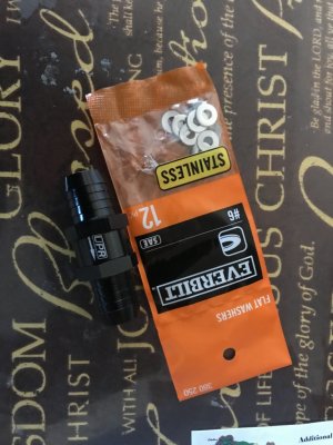
Now this is what I was referring to creating here to realign airflow thru a larger TB when using the factory PCV system to help PCM w\ idle control using a larger TB:
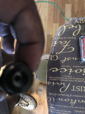
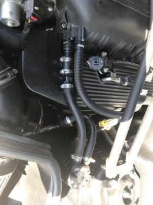
IMG_0112.JPG IMG_0111.JPG IMG_0113.JPG
Used a UPR 5/8" inline check valve w\ sliding plunger then picked up some #6 flat washers to use inside this check valve to do 2 things, 1. shim the spring to increase spring tension on sliding plunger AND 2. to serve as a control orifice (ID of washers is 1\8") as these will fit into the spring socket of this check valve so the check valve will operate as normal but the washers are also acting as an airflow control orifice along w\ the sliding plunger. I put 2 washers in it then installed this in the DS PCV system after catch can at intake manifold inlet DS of TB. Had recorded MAF g\s readings prior installation as follows...at hot idle (750 RPM's set in PCM for idle speed) MAF readings were fluctuating from 5.09-5.56 g\s w\ actual engine RPM's bouncing from 734-795 (this is the PCM making fine TB adjustments reacting to the MAF readings\engine RPM's to try to hold the 750 RPM idle setting thru a BBK #1763 62mm TB in conjunction w\ the PCV plunger orifice in DS valve cover....in my case a set of FR Black Wrinkle Etched valve covers which should be using the OEM designed PCV control valve w\ identical sized air control orifice. After static frictional pressure drop inside DS valve cover PCV valve which was designed to coincide w\ the OEM 55mm TB the air velocity has sped up but is now flowing thru an ADD W-1 v3 oil catch can causing air oscillation thru it so air volume delivery rate into intake manifold is high but isn't very linear so PCM is constantly hunting to control the idle speed using the amount of air after MAF section that is directed thru the TB by the friction created from the PCV valve orifice when the PCV valve plunger engages the seat during high manifold vacuum operation thru closed TB butterfly blades that are larger than the OEM TB unit). Can hear the engine exhaust tone constantly changing due to this occurring.
After installation of this device & restart of car I checked MAF readings again & found them much more stable holding between 5.21-5.35 g\s w\ engine RPM's bouncing between 748 to 762 (PCM showing to have a much improved idle control command of the engine idle thru the 62mm TB due to MAF signal stabilization thus verifies the device has restricted thus rerouted more than enough air volume back thru the TB so the PCM can actually control the flow thus stabilize the MAF signal thus stabilize the engine RPM's closer to the set RPM of 750. The device has also stabilized the airflow into the intake manifold thru the PCV system as well by creating a clean frictional pressure drop flow velocity across a smooth orifice at the intake port which slowed the air volume velocity upstream of it thru the DS valve cover causing the internal PCV valve to open up somewhat thus removing the vortex which can potentially draw excess oil vapor out & slowing the air volume velocity thru the catch can thus enhancing it's ability to strip any oil vapors carried in the air stream & reducing any air oscillation thru it as well thus assisting in maintaining better linear airflow thru the entire intake system which is also reflected in the stabilized MAF readings & engine idle RPM swing range difference post device install. I then removed the oil level dipstick in the catch can & verified that we still have vacuum present in the PCV system upstream of the device, although greatly reduced vs prior device install, thus verifying that system is still drawing air thru the CC from the CAI upstream of the TB thus removing CC blow by gasses as originally designed). Due to this stabilization I also saw the PCM readjust the LTFT's at idle (closer back towards 0%) due to this as well (less fluctuation in MAF signal, the more accurately the PCM can dial in the correct amount of fuel for the measured weighted air volume which will also help to stabilize the engine idle RPM's w\ some slight potential of improved idle fuel economy).
Made several snap throttle hits to observe engine recovery to idle....all went smoothly w\ engine RPM's dropping back to idle normally. Engine idle is much, much smoother now than prior verifying that PCM isn't fluctuating the TB trying to hunt anymore. Checked response by cycling the AC compressor on & off....when compressor is switched on the MAF readings instantly climb from the 5.21-5.35 g\s range to 5.83-6.03 g\s range w\ engine idle RPM's holding close to established RPM range (742-774 vs 748-762) but once compressor is switched off all resets back to established ranges within seconds...verifies how quick the PCM is controlling the engine RPM's thru load changes at idle since device install (and how well this 62mm TB can control the low end if it has enough of the existing measured air volume flowing thru it). Noted that the TPS angle readout seldom moved from the 13.3% blade angle (couple of instances it moved from 13.3% to 13.7%) while doing this though it is obvious that the PCM is actuating the TB butterflies (verified by the MAF reading changes) so either the amount of TB butterfly movement is falling within the TPS calibration scaling markers or we have ID'd a flat spot in the TPS sensor's analog resistor windings so has lost some fine angle movement scaling output in this area....something to look into later.....PCM uses this reading in it's load% (torque) calcs.

Didn't get the chance to drive the car yet after device install to observe operation under actual driving conditions today but will do so in the AM (had other items to attend to at the time) but all is looking well so far.

More testing to come...…………………..
 

Midlife Crises

Senior Member
Joined
Jul 20, 2019
Posts
1,855
Reaction score
1,265
Location
Fairbanks, Alaska
I like the idea of controlling the air bypassing the throttle body but I’m not sure a 1/8” orifice will vent the CC at 6,000 rpm.
 

teeje

Member
Joined
Mar 7, 2017
Posts
563
Reaction score
102
Location
Ohio
Now this is what I was referring to creating here to realign airflow thru a larger TB when using the factory PCV system to help PCM w\ idle control using a larger TB:
View attachment 70766 View attachment 70767 View attachment 70768
Used a UPR 5/8" inline check valve w\ sliding plunger then picked up some #6 flat washers to use inside this check valve to do 2 things, 1. shim the spring to increase spring tension on sliding plunger AND 2. to serve as a control orifice (ID of washers is 1\8") as these will fit into the spring socket of this check valve so the check valve will operate as normal but the washers are also acting as an airflow control orifice along w\ the sliding plunger. I put 2 washers in it then installed this in the DS PCV system after catch can at intake manifold inlet DS of TB. Had recorded MAF g\s readings prior installation as follows...at hot idle (750 RPM's set in PCM for idle speed) MAF readings were fluctuating from 5.09-5.56 g\s w\ actual engine RPM's bouncing from 734-795 (this is the PCM making fine TB adjustments reacting to the MAF readings\engine RPM's to try to hold the 750 RPM idle setting thru a BBK #1763 62mm TB in conjunction w\ the PCV plunger orifice in DS valve cover....in my case a set of FR Black Wrinkle Etched valve covers which should be using the OEM designed PCV control valve w\ identical sized air control orifice. After static frictional pressure drop inside DS valve cover PCV valve which was designed to coincide w\ the OEM 55mm TB the air velocity has sped up but is now flowing thru an ADD W-1 v3 oil catch can causing air oscillation thru it so air volume delivery rate into intake manifold is high but isn't very linear so PCM is constantly hunting to control the idle speed using the amount of air after MAF section that is directed thru the TB by the friction created from the PCV valve orifice when the PCV valve plunger engages the seat during high manifold vacuum operation thru closed TB butterfly blades that are larger than the OEM TB unit). Can hear the engine exhaust tone constantly changing due to this occurring.
After installation of this device & restart of car I checked MAF readings again & found them much more stable holding between 5.21-5.35 g\s w\ engine RPM's bouncing between 748 to 762 (PCM showing to have a much improved idle control command of the engine idle thru the 62mm TB due to MAF signal stabilization thus verifies the device has restricted thus rerouted more than enough air volume back thru the TB so the PCM can actually control the flow thus stabilize the MAF signal thus stabilize the engine RPM's closer to the set RPM of 750. The device has also stabilized the airflow into the intake manifold thru the PCV system as well by creating a clean frictional pressure drop flow velocity across a smooth orifice at the intake port which slowed the air volume velocity upstream of it thru the DS valve cover causing the internal PCV valve to open up somewhat thus removing the vortex which can potentially draw excess oil vapor out & slowing the air volume velocity thru the catch can thus enhancing it's ability to strip any oil vapors carried in the air stream & reducing any air oscillation thru it as well thus assisting in maintaining better linear airflow thru the entire intake system which is also reflected in the stabilized MAF readings & engine idle RPM swing range difference post device install. I then removed the oil level dipstick in the catch can & verified that we still have vacuum present in the PCV system upstream of the device, although greatly reduced vs prior device install, thus verifying that system is still drawing air thru the CC from the CAI upstream of the TB thus removing CC blow by gasses as originally designed). Due to this stabilization I also saw the PCM readjust the LTFT's at idle (closer back towards 0%) due to this as well (less fluctuation in MAF signal, the more accurately the PCM can dial in the correct amount of fuel for the measured weighted air volume which will also help to stabilize the engine idle RPM's w\ some slight potential of improved idle fuel economy).
Made several snap throttle hits to observe engine recovery to idle....all went smoothly w\ engine RPM's dropping back to idle normally. Engine idle is much, much smoother now than prior verifying that PCM isn't fluctuating the TB trying to hunt anymore. Checked response by cycling the AC compressor on & off....when compressor is switched on the MAF readings instantly climb from the 5.21-5.35 g\s range to 5.83-6.03 g\s range w\ engine idle RPM's holding close to established RPM range (742-774 vs 748-762) but once compressor is switched off all resets back to established ranges within seconds...verifies how quick the PCM is controlling the engine RPM's thru load changes at idle since device install (and how well this 62mm TB can control the low end if it has enough of the existing measured air volume flowing thru it). Noted that the TPS angle readout seldom moved from the 13.3% blade angle (couple of instances it moved from 13.3% to 13.7%) while doing this though it is obvious that the PCM is actuating the TB butterflies (verified by the MAF reading changes) so either the amount of TB butterfly movement is falling within the TPS calibration scaling markers or we have ID'd a flat spot in the TPS sensor's analog resistor windings so has lost some fine angle movement scaling output in this area....something to look into later.....PCM uses this reading in it's load% (torque) calcs.

Didn't get the chance to drive the car yet after device install to observe operation under actual driving conditions today but will do so in the AM (had other items to attend to at the time) but all is looking well so far.

More testing to come...…………………..
I wish this had something to do with the throttle body honestly but it did it with the stock one also. :/ .. here is a video. Take a look.


Sent from my iPhone using Tapatalk
 

GlassTop09

Senior Member
Joined
May 24, 2019
Posts
1,142
Reaction score
525
Location
Farmington, NM
I wish this had something to do with the throttle body honestly but it did it with the stock one also. :/ .. here is a video. Take a look.


Sent from my iPhone using Tapatalk
Now seeing this video is verifying to me that your issue seems to be purely electrical in nature & will require some DMM (or oscilloscope) usage to check\test the control signals from the APP--accelerator pedal position--sensors & wiring between them & PCM and\or from PCM TB actuator driver module (essentially from the PCM terminals that output power to the TB actuator motor) & TPS I\O terminals at PCM for proper 5v reference voltage output & proper comms, wiring between the PCM & TB & TPS sensor for signal integrity & proper comms (no flat spots/signal voltage spiking) across it's full range of movement but especially at/near TB close position and\or all wiring connections\connectors for signal integrity\fidelity.

A quick & easy initial check method is to use an OBDII scan tool that can read\display the APP, TPS & TB signal position % PID's thru the live data (not all general OBDII scan tools can do this so be aware) then look for any of these readouts fluctuating during idle (the APP % readouts shouldn't show any reading spiking\fluctuation, the TB_R% readout shouldn't be spiking, the TB_B% readout shouldn't be spiking but may move very slight due to PCM commanding fine movements to adjust TB butterflies to control idle & TPS% readout shouldn't be spiking\fluctuating unless PCM is actually commanding movement which will show thru the 2 TB PID's given) then slowly press the accel pedal & observe these readout's movements....any movement should be smooth & linear w\ your pedal movement. If any of these readouts show an excessively large movement on a small pedal movement you've located which side the issue is residing at then can follow up w\ a DVOM or scope to verify exactly what the source of the issue is to determine what to repair\replace. To increase the live data fidelity thru your scan tool use the custom data view & select these ETC (electronic throttle control) PID's alone so the scan tool won't waste time cycling thru the other PID's when using the full data view selection...you could miss the issue occurring while the scan tool is cycling thru the other PID's that aren't related to the ETC.

Most likely you have a sensor going bad (all APP sensors & TPS sensor are 5v analog sensors, will wear out over time & are especially prone to damage when the majority of movements are very small & remain within a very small area of movement due to current arcing across the contacts inside them)...the main 1 to fail is usually the TPS at the TB but in your case you may have 1 or more of the APP sensors--believe there's 3 of them total--wigging out since you've used 2 separate TB's w\ the same results...assuming of course that the same TPS wasn't being used w\ both of them) which is the easy\cheap side of this issue but it could also end up being the PCM itself which ain't so easy & cheap to replace (all 5v reference ETC control signal current\voltage to\from the APP & to\from the TB TPS & 12v TB actuator motor is generated thru the PCM regulated from fused 12v switched power thru BEC #42)....thus why all needs to be tested\checked to verify\pinpoint the source. Electrical issues can be very easy or very complicated to resolve & the older our S197's get the more of stuff like this to expect.

Hope this helps.
 

Latest posts

Support us!

Support Us - Become A Supporting Member Today!

Click Here For Details

Sponsor Links

Banner image
Back
Top