Wiring up gauges -- best place to splice in power supplies?

1950StangJump$

forum member
Joined
Apr 1, 2010
Posts
966
Reaction score
108
Brought my wiring (from the sensors) in through the rubber grommet at the driver's side foot well. Need to find convenient spots to splice in a 12+ battery, 12+ ignition, and a 12 volt with parking/headlamps on (as a trigger for the gauges to switch colors when the lights are turned on).

I want to avoid having to take the stereo out, so hoping there are good spots by the steering column. Anyone gone through this and can suggest some? Please save me the time to test :)
 

46addict

13726548
Joined
Aug 25, 2016
Posts
1,832
Reaction score
56
Location
Lawrenceville, GA
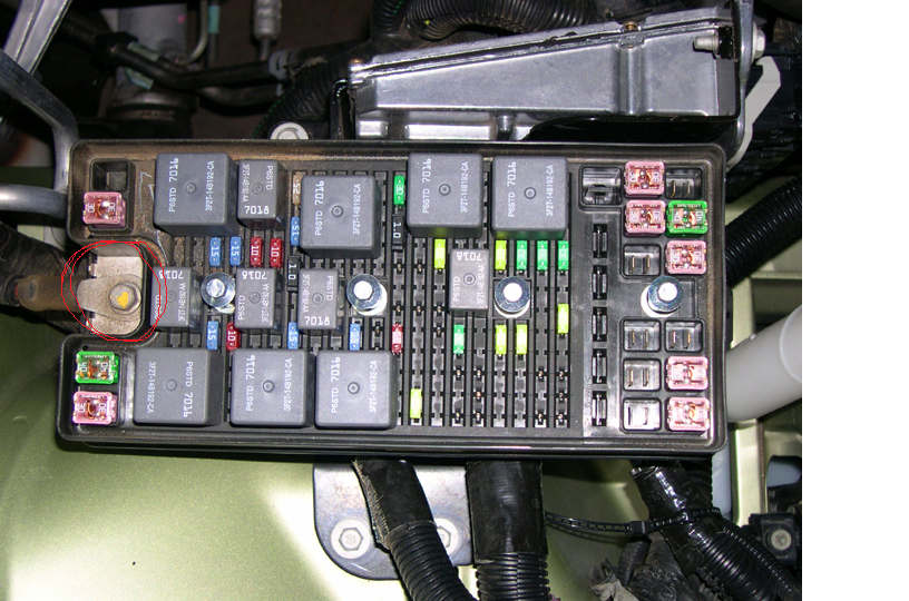
12v power: There is a hot lead on the BEC (engine bay fuse box). See pic.
Key on power: Fuses 2.8 (instrument cluster) and 2.20 (radio) at the SJB (pass side kickpanel box) are good ones. The radio gets power at key position 1 and the instrument cluster lights up at position 2 if that matters. There are lots of key on sources at the BEC too if you don't want wires coming back through the passenger side grommet.
Parking lamp dim: There is a yellow wire connected to the headlight switch. Splice here to get the lights to dim/change colors with the lights.

 
Last edited:

1950StangJump$

forum member
Joined
Apr 1, 2010
Posts
966
Reaction score
108
Hey, thanks for the quick reply. The headlight switch wire info is exactly what I needed. As for the others, I was hoping someone had info on what wires I could tap that were already near the bottom of the steering column by the driver's feet? I'll run new wires from the BEC if I have to, but would rather not if there are quick and convenient ways to grab it where I need it.

EDIT: I guess I can pull lines from the passenger kick panel as you suggest . . . if there isn't a better alternative at the steering column. I don't mind splicing and soldering, if there are lines there where I need them.
 
Last edited:

46addict

13726548
Joined
Aug 25, 2016
Posts
1,832
Reaction score
56
Location
Lawrenceville, GA
I don't know the wiring schematic well enough to know what areas on the driver's side are available for splicing.
 

sman247

forum member
Joined
Nov 17, 2014
Posts
130
Reaction score
7
I used the smart junction box on the passenger side. Just used a few add a circuits
 

redfirepearlgt

forum member
Joined
Mar 19, 2011
Posts
2,497
Reaction score
263
Hey, thanks for the quick reply. The headlight switch wire info is exactly what I needed. As for the others, I was hoping someone had info on what wires I could tap that were already near the bottom of the steering column by the driver's feet? I'll run new wires from the BEC if I have to, but would rather not if there are quick and convenient ways to grab it where I need it.

EDIT: I guess I can pull lines from the passenger kick panel as you suggest . . . if there isn't a better alternative at the steering column. I don't mind splicing and soldering, if there are lines there where I need them.

There is another option if the car is a stick shift car. It will require lifting out the console but that is small potatoes. Underneath you will find the connector that would have been used for the automatic shifter. C307 is the connector. Light Brown/ Red is the panel illumination power through the instrument panel dimmer, yellow with light green is the ignition enabled 12vdc, red with black is the 12vdc hot at all times which passes back through the low current board of the smart junction box and out to a 30amp 12vdc fused source, and black is ground.

Below is a link to the wiring page in the Ford tech wiring manual. I used this connector on my 2005 for my triple gauge dash mounted setup. Worked nicely.
http://iihs.net/fsm/?d=40&f=Shift Interlock.pdf
NOTE: It may be possible that the wiring color coding has changed from revision to revision so verify sources before assuming with a voltmeter if the color codes are different.
 

1950StangJump$

forum member
Joined
Apr 1, 2010
Posts
966
Reaction score
108
There is another option if the car is a stick shift car. It will require lifting out the console but that is small potatoes. Underneath you will find the connector that would have been used for the automatic shifter. C307 is the connector. Light Brown/ Red is the panel illumination power through the instrument panel dimmer, yellow with light green is the ignition enabled 12vdc, red with black is the 12vdc hot at all times which passes back through the low current board of the smart junction box and out to a 30amp 12vdc fused source, and black is ground.

Below is a link to the wiring page in the Ford tech wiring manual. I used this connector on my 2005 for my triple gauge dash mounted setup. Worked nicely.
http://iihs.net/fsm/?d=40&f=Shift Interlock.pdf
NOTE: It may be possible that the wiring color coding has changed from revision to revision so verify sources before assuming with a voltmeter if the color codes are different.

Great info! I'm going that direction. Although for my 2008 GT, the colors were:

1. 12vdc hot at all times: Yellow/green
2. 12vdc ignition: Purple/white
3. Dimmable lights: Green/red
4. Ground: black

And, unfortunately, my Prosport gauges use LED lighting, so they are not dimmable. When you try to dim them, it assumes you are turning the lights off and switches back from the nighttime color (green) to the daytime color (white). In other words, the power to the dimmable light source is a "trigger" for the lights to go to the nighttime color and, when dimmed, the gauge assumes the trigger is deactivated.

Will probably still use that lighting source though and just not dim them -- the alternative is to have to drag a line from a parking light all the way into the car for the "nighttime trigger."
 

1950StangJump$

forum member
Joined
Apr 1, 2010
Posts
966
Reaction score
108
Thought I would circle back as a close out.

For some reason, the 12 volt power supplies at that connector were not sufficient. The gauge LEDs would literally pulsate and go dim. I thought it was the ground, but that wasn't it. As soon as I took the time to run the 12vdc hot and the 12vdc ignition to the spare SJB spots, the problem was solved. The power at that connector in the center console tested out at 12 volts, so I'm still not sure what the problem was. But, all's well that ends well.
 

redfirepearlgt

forum member
Joined
Mar 19, 2011
Posts
2,497
Reaction score
263
Thought I would circle back as a close out.

For some reason, the 12 volt power supplies at that connector were not sufficient. The gauge LEDs would literally pulsate and go dim. I thought it was the ground, but that wasn't it. As soon as I took the time to run the 12vdc hot and the 12vdc ignition to the spare SJB spots, the problem was solved. The power at that connector in the center console tested out at 12 volts, so I'm still not sure what the problem was. But, all's well that ends well.

Interesting. The only thing different was that mine had incandescent bulbs and not LED's. I pulled everything from that source. Oh and I did not have any need for a 12vdc hot at all times source. That hot all the time source does go through the low current sensing board and is designated as used to disengage the Park solenoid. So that may have been a poor selection. Sorry.
 

1950StangJump$

forum member
Joined
Apr 1, 2010
Posts
966
Reaction score
108
Interesting. The only thing different was that mine had incandescent bulbs and not LED's. I pulled everything from that source. Oh and I did not have any need for a 12vdc hot at all times source. That hot all the time source does go through the low current sensing board and is designated as used to disengage the Park solenoid. So that may have been a poor selection. Sorry.

Hey, its good now, so I'm happy. When I was trying to diagnose the issue, I confirmed it was not the ground, but then ran both the 12 hot and the 12 ignition to the battery . . . which fixed the problem. So, I just ran both to the SJB. In retrospect, based on your post, it was probably only the 12vdc hot at all times that was the issue.
 

Shotokan1509

forum member
Joined
Aug 13, 2008
Posts
3,917
Reaction score
82
Location
CT
Digging up this old thread, trying to install Innovate PSB-1 in my 06 stick car, going to get power from fusebox using add a fuse, probably run ground all the way to battery what I'm having trouble with is dimmer wire. Innovate instructions in capital letters state do not connect to headlight dimming wire off the switch. I was going to do whats stated above pulled center console but I have different colored wires and the car battery is both dead and not in the car for me to test. Anyone know what an 06 gt wire I want to tap for headlight on/off? I tried the online manuals but not having luck figuring it out, I have:

Tan with white tracer
blue with red tracer
blue with yellow tracer
yellow with green tracer
red with black tracer
solid black
 

bambam 06

Member
Joined
Aug 12, 2018
Posts
141
Reaction score
38
Digging up this old thread, trying to install Innovate PSB-1 in my 06 stick car, going to get power from fusebox using add a fuse, probably run ground all the way to battery what I'm having trouble with is dimmer wire. Innovate instructions in capital letters state do not connect to headlight dimming wire off the switch. I was going to do whats stated above pulled center console but I have different colored wires and the car battery is both dead and not in the car for me to test. Anyone know what an 06 gt wire I want to tap for headlight on/off? I tried the online manuals but not having luck figuring it out, I have:

Tan with white tracer
blue with red tracer
blue with yellow tracer
yellow with green tracer
red with black tracer
solid black


Go here on page two.

Main Light Switch
 

Shotokan1509

forum member
Joined
Aug 13, 2008
Posts
3,917
Reaction score
82
Location
CT
Innovate agreed fine for headlight switch, tapped the tan with white tracer and seems to work. Thanks
 

Support us!

Support Us - Become A Supporting Member Today!

Click Here For Details

Sponsor Links

Banner image
Back
Top