You are using an out of date browser. It may not display this or other websites correctly.
You should upgrade or use an alternative browser.
You should upgrade or use an alternative browser.
Connector Location
- Thread starter Laga
- Start date
redfirepearlgt
forum member
- Joined
- Mar 19, 2011
- Posts
- 2,497
- Reaction score
- 263
C431 is shown in the drawing below. However if this is a 2005-2009 pin 8 is not used. Pin 1 however is color coded LightGreen/violet stripe and runs from the SMJ to the Fuel tank unit. Disregard the highlighted area taht was with regard to a non related issue. As for C234, are you sure you don't mean C423 pin 14? See print below. It is also in the location drawing.


redfirepearlgt
forum member
- Joined
- Mar 19, 2011
- Posts
- 2,497
- Reaction score
- 263
post up what you find.
Will do later this week. . It’s an 05. The gas gauge tends to stay between half and 3/4. Sometimes it will go to full after a fill up , but takes like 20 miles to do so. Never goes below 1/2. The info center on the dash is 95% accurate in gas used. The stepper motors on the instrument cluster were changed about 10 years ago. The SJB has never been wet and is in perfect condition. There is no continuity at pin 31 and 44 in the C 2280c connector with the the jumper installed at C433. Everything points to a open circuit somewhere.
redfirepearlgt
forum member
- Joined
- Mar 19, 2011
- Posts
- 2,497
- Reaction score
- 263
That be the case you then need to separate at C431, jumper out pins 1,2 and then see if you read continuity (with a meter...some try to use test lights...not a good idea in this case) and check same. If still infinity move next to C423. I am assuming you had a resistance value at the tank connector C433 pins 2/4 on the tank side of the circuit with it isolated.
If you need more page shots let me know. I find it easier to use a paper form than the online that is available here. That said the online is very nice when you have nothing else. Just takes more time to find things and work between pages. Plus there are some things missing.
If you need more page shots let me know. I find it easier to use a paper form than the online that is available here. That said the online is very nice when you have nothing else. Just takes more time to find things and work between pages. Plus there are some things missing.
DieHarder
Senior Member
- Joined
- Nov 9, 2019
- Posts
- 1,467
- Reaction score
- 758
Troubleshooting procedure for that is in Section 413 (Instrumentation); Pinpoint Tests A
Unfortunately, the online manual jumps around. In my manual these are listed as Pinpoint Test B but the links are to troubleshoot the fuel gauge so that's what you want. Should help you narrow down where the fault is. Good luck.
https://iihs.net/fsm/?d=343&f=Instrument Cluster.pdf&p=2 (Fuel gauge operation/General description)
https://iihs.net/fsm/?d=343&f=Instrument Cluster.pdf&p=57 (Pinpoint Test A starting pg 9)
https://iihs.net/fsm/?d=343&f=Instrument Cluster.pdf&p=58 (Pinpoint Test A pg 10)
https://iihs.net/fsm/?d=343&f=Instrument Cluster.pdf&p=3 (Pinpoint Test A pg 11)
https://iihs.net/fsm/?d=343&f=Instrument Cluster.pdf&p=4 (pg 12) followed by pg 13 to pg 20)
https://iihs.net/fsm/?d=343&f=Instrument Cluster.pdf&p=12 (pg 20 End of fuel gauge testing).
Thanks Dieharder, I worked through those steps yesterday. That's how I came to conclusion of open circuit.
Redfirepearlgt, is there a layout of the PIN numbers for C431 and C423 for jumper wires, or do I go by wire colors?
Redfirepearlgt, is there a layout of the PIN numbers for C431 and C423 for jumper wires, or do I go by wire colors?
redfirepearlgt
forum member
- Joined
- Mar 19, 2011
- Posts
- 2,497
- Reaction score
- 263
Here ya go boss.


Found C431 at rear corner at bottom of gas tank. It had some light corrosion which was cleaned up and had a resistance value coming from fuel level sensors when done. 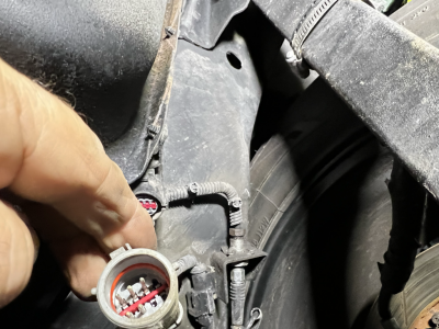
C423 is behind rear interior panel on drivers side. I am unable to access it at this time because of my recently dislocated hip.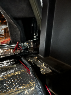
However, I made some other discoveries.
There is an open at circuit 29. The remedy according to Ford Service is to repair open circuit 1357 which is the return for the two fuel level sensors. (see above)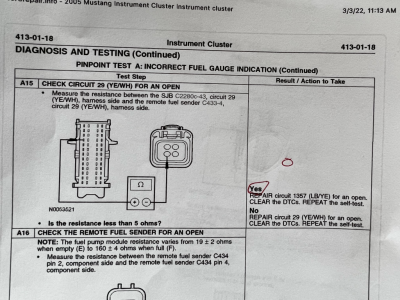
But it also has a short to voltage for 1357. .08 volts present.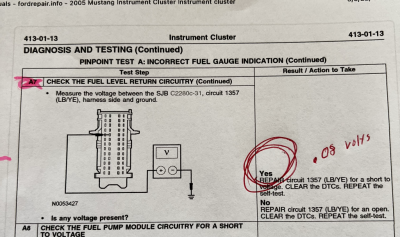
Im also showing a short to voltage at 1356, with .03 volts.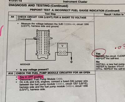
How can there be a short to voltage and open on same circuit?
If C423 checks out OK, Saturday when I get some help. Am I correct in thinking to replace the wires from the fuel level sensors at the hats to the C2280-c connector at SJB? Thanks

C423 is behind rear interior panel on drivers side. I am unable to access it at this time because of my recently dislocated hip.

However, I made some other discoveries.
There is an open at circuit 29. The remedy according to Ford Service is to repair open circuit 1357 which is the return for the two fuel level sensors. (see above)

But it also has a short to voltage for 1357. .08 volts present.

Im also showing a short to voltage at 1356, with .03 volts.

How can there be a short to voltage and open on same circuit?
If C423 checks out OK, Saturday when I get some help. Am I correct in thinking to replace the wires from the fuel level sensors at the hats to the C2280-c connector at SJB? Thanks
redfirepearlgt
forum member
- Joined
- Mar 19, 2011
- Posts
- 2,497
- Reaction score
- 263
I would focus on continuity tests with regard to wiring first.
Disconnect C433, C434, and C2280c connectors. KEY OFF. In this state put the multimeter to measure ohms. Then begin checking each wire to chassis ground.
C434 pin 4 - red lead
chassis ground - black lead. Should read infinity.
C434 pin 2 - red lead
chassis ground - black lead. Should read infinity.
C433 pin 4 - red lead
chassis ground - black lead. Should read infinity.
D433 pin 2 - red lead
chassis ground - black lead. Should read infinity.
The last is redundant because pin 2 of D433 shares a junction point (s230) with C434 pin 2. But do it just for grins.
This confirms you have NO shorts in your wiring.
The next step is to check continuity of the wiring between the connectors.
C434 pin 2 - red lead
C2280c-31 - black lead. you should read less than 2 ohms.
C434 pin 4 - red lead
C2280c pin 43 - black lead. you should read less than 2 ohms.
C433 pin 2 - red lead
C2280c pin 31 black lead. you should read less than 2 ohms.
C433 pin 4 - red lead
C280 pin 44 - black lead. you should read less than two ohms.
If these all check accordingly you have good wiring. The next step IMHO would be to check the resistance on the tank float (C433 -pin 2 to pin 4 on the tank side). It should read 19 ohms empty and up to 160 ohms full. The reading will be somewhere in between which would be good. So half tank if this is linear should read about 70 ohms. 1/4 tank about 35 ohms, and 3/4 tank about 105 ohms. If you can pull the fuel unit and cycle the float switch throughout its range you should see it vary smoothly form 19 to 160 ohms. The latter would be the best check.
This is a start. I will look at some other things in the prints at home. If all of this looks good this brings us down to 3 items - The gauge, the SJB or the other fuel sender on C434. Still trying to figure out what that is for but i believe it is a temp sensor or pressure sensor for the tank. It may not apply to the problem but I may be wrong. Someone correct me or fill us in on the function of that second sender that is indicated to be by its symbol a pressure or temp sensor.
Wow, thanks, Both fuel level sensors have been pulled and tested in the past couple of weeks. They both work perfectly out of the tank and in. I tested the drivers side, this morning. It was 138 ohms. Will do those tests tomorrow morning.
redfirepearlgt
forum member
- Joined
- Mar 19, 2011
- Posts
- 2,497
- Reaction score
- 263
btw on the continuity tests (not the isolation tests in the first part) you can ground one end being tested to frame with a piece of wire or aligator clip test lead, and then simply connect to frame ground with black lead and probe associated pin with red lead. otherwise get a long piece of wire. i would do the former if feasible first.
sorry i did not look into prints further last night. if voltage checks like being described in the tech manual are needed we will need to determine which signals are source (voltage seen in normal operation) verses completion of path to ground (the other side of the circuit after said component that completes path to ground.
sorry i did not look into prints further last night. if voltage checks like being described in the tech manual are needed we will need to determine which signals are source (voltage seen in normal operation) verses completion of path to ground (the other side of the circuit after said component that completes path to ground.
Last edited:
Update,
Long story short. Fuel gauge has worked but wasn’t accurate for about 2 years.
New passenger side fuel level sensor, which was tested and installed a couple of months ago when I installed a larger fuel line for E85, was showing a resistance value of 52 ohms when it should have been around 160 ohms with a full tank. I removed it from the car and it performed perfectly when bench tested. Once reinstalled, it produced the 162 ohms it should. After reconnecting all electrical parts, I turned on the key, and the gauge on the dash read correctly (full).
Since the new sensor was installed in the proper orientation, my guess is this means either the new unit is somehow defective, or, the crossover line inside the tank is loose and interfering with the float. This would explain why the gas gauge has not been accurate for some time now. Im going to put things back together and see if it continues to operate correctly. If it happens again, I’ll gently remove ring and peak in with a bore scope to see if line is touching float.
Thank you very much Redfirepearlgt for your knowledge and help.
redfirepearlgt
forum member
- Joined
- Mar 19, 2011
- Posts
- 2,497
- Reaction score
- 263
NO PROBLEM! LOVED HELPING!
redfirepearlgt
forum member
- Joined
- Mar 19, 2011
- Posts
- 2,497
- Reaction score
- 263
gotcha. Cool. We have had float switches at work crack or start to dissolve and fill with cutting coolant and cause low tank alarms when the coolant level is fine.
To clarify the schematics, because it's a saddle tank with venturi siphon from passenger to driver side the passenger side of the tank empties first. There are 2 level sender floats one on each side. The boards on each read 15 ohms low to 160 ohms high and work independent and in tandem. The passenger side sender drives the gauge from full to 1/2 tank. And the driver side sender drives the gauge from 1/2 down to empty.
Because of this design the circuit can do funny stuff. You could disconnect one or the other and the remaining one would still drive the gauge properly in its respective half tank range.
However, if the siphon isn't working properly to empty passenger side first while driver side stays full or one sender is broken/shorted corroded that's when gauge readings can do weird stuff, fluctuate or not read correctly.
This is because the driver side should be at high 160 ohms the entire time the passenger side is traveling down from full 160 to empty 15 and gauge runs from full to half. Then once the p side is empty and that sender stays at full low 15. Then the driver side will start to run down from 160 as you go down from 1/2 tank towards empty.
Because of this tandem function if a sender on either side is not where it's reading should be when the other is traveling it will cause issues.
The way I troubleshoot senders is visual inspection of each. Clean the resistance boards, check for cracks, and occasionally resolder the wire point to the board as needed. Then manually bench test each float through travel and ensure the pick up arm maintains full contact with the board and then manually move and read resistance through the entire range. Once that's verified I reinstall and full fill up.
From there if both senders bench tested good and there are still issues, I suspect the stepper motor in the gauge cluster that drives the needle as it's a known problematic failure point.
Additionally to verify the siphon is good (as a bad siphon can cause bad readings). I wait until half tank or suspected half tank is reached and pop open the hats. I'm looking to make sure passenger side is completely empty and driver side is completed full.
Things I've seen: guys can kink or bend the internal line while doing a pump install. This can cause siphon issues leading to sender issues. Or not fully click it back on causing the same problem. Also guys bend crack or break senders during pump install. Sometimes they are just dirty and need cleaned. Lastly there is a bucket wall inside the tank on the driver side that the pump sits in and the sender arm needs to go outside the bucket wall towards the center of the car. I've seen the float jammed on the wrong side of the wall this is easy to do if fuel level is too low during install.
I've never got to the point of needing to check wiring back to the sjb and cluster from the senders.
05/06 specifically as of lately if no fuel work was done recently, its usually the stepper motor in the cluster failing. Occasionally its due to a dirty board or worn or corroded board wire connection.
Edit. I should add another issue is the resistance of the sender board changed in 2010. Guys sometimes mix up a 10-12 sender or gt500 hat onto a 05-09 car with the wrong sender.
Last edited:
redfirepearlgt
forum member
- Joined
- Mar 19, 2011
- Posts
- 2,497
- Reaction score
- 263
^^^ Thanks Jeremy. Appreciate the theory of operation. Makes sense. After realizing that there are two sensors truly in play (though page 60-3 had me second guessing in the prints because of the symbol difference used on the two sensors) I figured there was some tandem process going on. I was unaware that one side emptied before the other. I thought the pump pulled from both sides simultaneously. Because the Ford manual references the symbol as a potentiometer....BUT also indicates it could be a pressure or temp sensor reference (page 4-1 Symbols) and given it is drawn different than the one on the pump side, I was led to falsely conclude that this sensor was simply sharing the same voltage source, but likely a pressure sensor (non related) that monitors tank pressure for the fuel cap integrity or even a fuel temp sensor. Thanks for the clarification and learning lesson!
Last edited:
Similar threads
- Replies
- 0
- Views
- 331
- Replies
- 1
- Views
- 91
- Replies
- 1
- Views
- 105
Support us!
Support Us - Become A Supporting Member Today!
Click Here For Details


