07 mustang PCM not grounding 02 heater

94_cobra

forum member
Joined
Mar 16, 2017
Posts
52
Reaction score
0
so my 07 keeps throwing a code for p0155 heater ground issue.

swapped out sensors and from side to side etc. further testing and research shows pin 70 of the pcm should provide ground to bank 2 front sensor. it does not. bank 1 front sensor is getting the ground from the pcm pin 69 like it should, but the pm is not spitting out a ground for the bank 2 sensor, making it throw a code for heater ground.

so my questions is... what does this mean? Is my computer bad?

the car runs like shit unless i turn off the front 02 sensors in the tune.. which i prefer not to do, plus the light stays on regardless
 

redfirepearlgt

forum member
Joined
Mar 19, 2011
Posts
2,497
Reaction score
263
If you back probe pin 70 on C175E and still read 12vdc with the key on, next do a compare and see if you are reading a logic low on pin 69 which would indicate that bank 1 heater is being properly sinked to ground at key on by the PCM and Bank 2 is not.

For reference pin 70 color code should be yellow with light blue stripe and pin 69 is red with white stripe according to the 2005 4.6L schematics.

Just in case and for added prove out you could also disconnect O2 sensor bank 2 C172 from the sensor and C175E from the PCM and check continuity between pin 70 of C175E and pin 1 C172 of the O2 sensor connector. If that rings out you can then conclude that the PCM is likely bad assuming you have tried a known good O2 sensor replacement on your TS process.

If the voltage source fuse F47 was blown you would have MAF Temp sensor codes, evap canister codes, IMRC, and all kinds of other CEL codes.
 

94_cobra

forum member
Joined
Mar 16, 2017
Posts
52
Reaction score
0
If you back probe pin 70 on C175E and still read 12vdc with the key on, next do a compare and see if you are reading a logic low on pin 69 which would indicate that bank 1 heater is being properly sinked to ground at key on by the PCM and Bank 2 is not.

For reference pin 70 color code should be yellow with light blue stripe and pin 69 is red with white stripe according to the 2005 4.6L schematics.

Just in case and for added prove out you could also disconnect O2 sensor bank 2 C172 from the sensor and C175E from the PCM and check continuity between pin 70 of C175E and pin 1 C172 of the O2 sensor connector. If that rings out you can then conclude that the PCM is likely bad assuming you have tried a known good O2 sensor replacement on your TS process.

If the voltage source fuse F47 was blown you would have MAF Temp sensor codes, evap canister codes, IMRC, and all kinds of other CEL codes.

Thank you for the reply, those are the correct wire colors and I have Ran some test. I have found a few thing.

I pressed the connector into the pcm harder and pin 70 gets ground!! So the connector is loose, and now I get ground BUT didn't fix the problem.

I checked continuity between pin 70 and the 02 connector and it shows good.

So heres where it goes wrong.. it shows the ground it should have on the car side of the 02 harness plug, but when I plug the sensor in, the ground goes away and both heater wires become battery voltage...

Bank 1 is fine. Meter shows it's getting ground when it's all plugged in. Bank 2 shows both heater wires have battery voltage when plugged in..
 
Last edited:

redfirepearlgt

forum member
Joined
Mar 19, 2011
Posts
2,497
Reaction score
263
I pressed the connector into the pcm harder and pin 70 gets ground!! So the connector is loose, and now I get ground BUT didn't fix the problem.

I checked continuity between pin 70 and the 02 connector and it shows good.

So heres where it goes wrong.. it shows the ground it should have on the car side of the 02 harness plug, but when I plug the sensor in, the ground goes away and both heater wires become battery voltage...

Bank 1 is fine. Meter shows it's getting ground when it's all plugged in. Bank 2 shows both heater wires have battery voltage when plugged in..

1.) I need to know what you mean by getting ground. Because an electronically sinked circuit (which is what you are dealing with) does not actually provide ground. The control device (usually a transistor of FET) is biased in such a way that it provides a logic low which is low enough potential to allow current flow in the circuit. If the circuit is properly working with ignition on/run (engine off), you should read 1.5vdc or less if the circuit is properly sinking the circuit low to turn on the heater. If you read 12dvc at C175E this means you have no logic low (either due to poor connection as you have described or the sinking device in the PCM is bad).

To read this you will actually need a needle probe to pierce the insulation of C175E-70 on the connector side with the connector plugged securely into the PCM socket and the car on. You will be checking for VDC with a voltmeter. The black probe will be attached to a known solid ground.

2.) Knowing the wire is good from O2 heater to C175E-70 is a good thing.

I hope this helps you out. Sinking and Sourcing circuits can be tricky for even an experienced electronics technician. If you wish for an explanation in the event you are not familiar with the terms I will be glad to make some simple drawings and post them for better understanding. I personally learned better through visual and then re-reading the chapter 5 times...minimum to get it through my dense head back in the day! LOL!
 
Last edited:

94_cobra

forum member
Joined
Mar 16, 2017
Posts
52
Reaction score
0
1.) I need to know what you mean by getting ground. Because an electronically sinked circuit (which is what you are dealing with) does not actually provide ground. The control device (usually a transistor of FET) is biased in such a way that it provides a logic low which is low enough potential to allow current flow in the circuit. If the circuit is properly working with ignition on/run (engine off), you should read 1.5vdc or less if the circuit is properly sinking the circuit low to turn on the heater. If you read 12dvc at C175E this means you have no logic low (either due to poor connection as you have described or the sinking device in the PCM is bad).

To read this you will actually need a needle probe to pierce the insulation of C175E-70 on the connector side with the connector plugged securely into the PCM socket and the car on. You will be checking for VDC with a voltmeter. The black probe will be attached to a known solid ground.

2.) Knowing the wire is good from O2 heater to C175E-70 is a good thing.

I hope this helps you out. Sinking and Sourcing circuits can be tricky for even an experienced electronics technician. If you wish for an explanation in the event you are not familiar with the terms I will be glad to make some simple drawings and post them for better understanding. I personally learned better through visual and then re-reading the chapter 5 times...minimum to get it through my dense head back in the day! LOL!


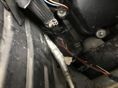
Thank you for your help sir! I found the little devil.. it seems someone has had their hands a little deeper into this car than I prefer.. this is the pin 70 (heater ground) wire
 

Attachments

  • IMG_1139.jpg
    IMG_1139.jpg
    490.7 KB · Views: 27

redfirepearlgt

forum member
Joined
Mar 19, 2011
Posts
2,497
Reaction score
263
Great job!! There's nothing tougher than dealing with an inept repair. That explains why you were reading 0 volts at C175E with key on engine off instead of what is known as logic low.

Take the time to repair those two wires properly so it does not get you again down the road. I highly suggest soldering and heat shrinking. Take the time to clean the flux off of the splice job with alcohol before shrinking the tubing over the splice.

U-DUH-MAN!
 
Last edited:

MM2_Heavy_Metal

Junior Member
Joined
Aug 30, 2022
Posts
1
Reaction score
0
Location
socal
Hi can someone help me with my 2007 mustang speedo & trans issue? I can't figure out how to start a new post or I would?

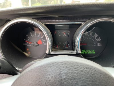
Last yr my daughters car failed smog test, Pxxx trans solenoid error code. She reported slipping in 3rd gear, I think she drove it this way for several months without telling me. I decided to rebuild the trans since it had 135k miles, (my fourth rebuild in a row, last was 5r55s in 05 exp, works perfectly). After rebuild the speedo immediately crapped out and won't shift correctly. It throws the P720 Out speed sensor error code. I replaced all 3 sensors, the PCM, new ford solenoid block, and rang out the wires, resistance checks are good from pcm connector, still no change. I just ran new wires to the OOS, it worked for a second, then crapped out. Any suggestions.

Would a bad stepper motor on the speedo cause this?

I'm thinking some other device is bad shorting out the common signal return. gray/red wire. 6 months ago it only showed the OOS error, now it had a few more, including the bank 2 front O2 sensor.

SpeedoError.jpeg
 

redfirepearlgt

forum member
Joined
Mar 19, 2011
Posts
2,497
Reaction score
263
You've def done your homework, and way ahead of me on transmission theory and application. don't know if I can be much help or not but sometimes even a dumb ass squirrel like me can stumble over a nut in the dark.

The three sensors you replaced (I assume it is these three) are OSS, TSS, and ISS. They share a common splice that provides signal return at C175t pin 41 (GR/RD wire). This reference return is common to all three sensors you replaced as well as the trans temp sensor and the tranmission selection operation through DTR sensor.

To check for a short in the wiring you could try this.

Disconnect C169 (OSS), C143 (TSS), C164 (ISS), C199 (isolates trans temp sensor), and C167 (DTR sensor). This isolates that entire harness section which has a common splice at S106 (see below). For added measure also disconnect C175t at the PCM. Now you can do a resistance check of that entire common section to frame ground and see if it is shorting to it due to chaffing somewhere via a resistance to ground check at any or all of the GY/RD wires at any connector you have pulled. If you read infinity or very high resistance that indicates that the harness section is not shorting to frame ground.

To verify the wiring in that area has no open (broken wire) try this.

The next thing you could do to ensure the harness integrity does not have an open is to check continuity from C175t pin 41 (this is the PCM ref return that the signals are seeking as I understand the schem), and each gry/rd wire on every given connector you have pulled should read continuity (less than 5 ohms).

This will verify your harness or isolate an issue. You already know more about the goings on in the trans operation/theory wise than I do, so I cannot help you out there beyond playing tiddly wink guessing games. I'm out of my league here. However the process above will isolate any issues in your wiring harness in that area or verify it so you can then focus elsewhere. the process is tedious and drawn out but if followed correctly should help you to fix a wiring issue or move on.

Good luck. I can post schem photos later if you need them. My wife is huffing that I have spent too much time here already this morning. (LOL).

-----------------------------------------------------------------------------------------------------------------
S106 location - If you follow the harness from the trans up to where the split is on the back side of the engine the splice (S106) is located in the harness toward the center of the engine (to the left from the trans side. to the right from the engine front side). Of course you would have to tear into the splice but I would not go there yet.
 

Latest posts

Support us!

Support Us - Become A Supporting Member Today!

Click Here For Details

Sponsor Links

Banner image
Back
Top