Lunati VooDoo #21270700 Camshafts

GlassTop09

Senior Member
Joined
May 24, 2019
Posts
1,142
Reaction score
525
Location
Farmington, NM
FYI........................

Here is provided some cat CE ratio results of my engine's PCM OBDII cat monitoring algorithm since me flashing in latest tune rev #32 which I revamped the VCT airload load% map & both Spark Advance\BKT & MBT VCT Spark Adder map settings to increase engine TQ output between .10 load thru .70 load areas to improve engine's part throttle drivability response while in CL Normal Mode:
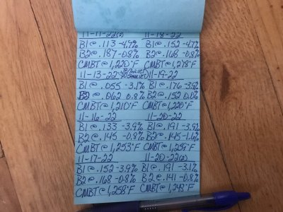
GlassTop09 Tune #32 Catalyst CE Ratio Recordings.JPG GlassTop09 Tune #32 Catalyst CE Ratio Recordings (2).JPG
Please note how the PCM is handling the cat CE ratio results since the initial DC where the PCM recorded the initial CE ratio results over subsequent Mode 6 Cat CE Ratio checks of these MF #5461336 CARB-cert TWC aftermarket cats as read from my trusty Foxwell NT301 general OBDII scan tool (that I keep stored in the car.......I have a general OBDII scan tool stored in all of our vehicles for monitoring purposes if a MIL lights up to see what's going on & to see if the DTC noted prevents the vehicle from being driven until I can address it......driving used vehicles).

You can clearly see where the PCM caught up w\ B2 cat 1st to get it under control then follow up catching up w\ B1 cat from today's drive\check then brought up B2 to match as both engine banks cats are monitored\adjusted by PCM using the O2 sensor feedback from both the front & rear O2 sensors during engine operation which includes EVAP purging, any environmental airmass changes that affect the MAF readings (like following behind other vehicles for starters thus engine is ingesting other vehicle's exhaust fumes into CAI which will throw off the calibrated MAF sensor airload calc's vs the LWFM MAF airload calc'd tables that PCM uses to check the MAF sensor accuracy to maintain accurate fueling along w\ the NB O2 sensor's STFT+LTFT O2 feedback while operating in CL Normal Mode.....what MAF Adaption is designed to compensate for) AND catalyst monitoring\operational maintenance. Also note how closely the engine idle LTFT readings are maintained thruout thus is indicative of how steady the PCM is also controlling the engine's AFR thru the EQ Ratio Lambda 1.0 formula using the fuel stoich AFR setting of 14.13 which matches the E10 unleaded 91 oct fuel's stoich AFR being burned by engine.

The PCM will continue to monitor\adjust this until the CE ratio results settle out & remain within a set range based on all the current tuning changes, engine usage concerning load%, environmental airmass changes encountered as well as the MF #5461336 cats' ability to adequately treat the exhaust they get from this modded engine's exhaust output. The PCM Cat CE Ratio max thresholds in tune are set @ .660 for both B1\B2 (the highest LEGAL threshold settings the PCM's current OS firmware will allow for this '09 MY S197) thus as you can also see, ain't nowhere close to the thresholds.......this is from an FBO, SBE NA 4.6L V8 equipped w\ a non-stock CAI (well, the Bullitt CAI is an OEM FoMoCo CAI but it didn't come installed from factory w\ this MY GT so is not "OEM"), non-stock TB (FP 62mm TB now correctly setup in tune), '08 OEM IM w\ CMCV's removed (the remedy to fix the EVAP issue caused by the FP 463V IM's bad EVAP port routing design into its plenum that helped cause the erroneous cat CE P0420\P0430 DTC's & also dyno tested\proved to not cause practically any HP\TQ loss w\ deleted CMCV's), Kooks 1 5\8" LTH's using corrected O2 transport delay timing settings that match the header's O2 sensor location & X-Pipe fitted w\ MF #5461336 CARB-cert TWC aftermarket cats that match this vehicle's VEI EFN# thus EPA legal & fitted w\ NGK 22060, 22500 NB O2 sensors running a set of Lunati VooDoo #21270700 aftermarket NSR\full VCT-compliant non-stock camshafts that are tuned using a highly modified tune file from OEM that has all pertinent OEM tune settings enabled\set to maintain good emissions compliance while also pushing as high a HP\TQ output as can be achieved.....safely & reliably.

So yes, this can be easily done w\ a NA 4.6L V8 using all aftermarket parts as long as the tuning that the PCM needs to properly maintain\control the cats CE ratio output thus emissions compliance is left intact & operational in tune file as none of it has any effect on the engine's ability to make max HP\TQ while NA......and the aftermarket parts being used don't cause an adverse effect to the PCM's ability to control\maintain the cats emissions compliance.

The only aftermarket part I found to yet have an adverse effect was the FRPP IM thru its poor EVAP port routing design. If Ford had designed this port like they did for the OEM IM, this aftermarket FRPP IM would have been fully capable of EPA certification.......only downside is that you couldn't have used an aftermarket mono blade TB on it...............

PS edit--If no one is actually monitoring the PCM Cat CE ratio test results or using a 5-gas analyzer to check engine exhaust while tuning these engines, you'd be in a very bad position of potentially misunderstanding how Ford set all this up & how all this actually works & is interrelated\integrated in this factory SO PCM's operations, thus can easily mess this up by unnecessarily altering\disabling needed settings in tune file to manage emissions that do not affect engine max HP\TQ output at all.....causing this engine to fail emissions cert tests it really shouldn't be failing. Aftermarket components usage for the most part w\ very few exceptions, isn't the problem.....................

My 2 cents.................
 
Last edited:

GlassTop09

Senior Member
Joined
May 24, 2019
Posts
1,142
Reaction score
525
Location
Farmington, NM
FYI..............................

Thought I'd put this here for those interested so when you're looking at your scan tool's live data you know what this part of your screen's data is representing:
View attachment 84809 View attachment 84810
These 2 pictures are showing the section of live data of the 2 front NB O2 sensor's (O2B1S1\O2B2S2) voltage reactions to PCM swinging the fueling to switch the O2 sensors........this reps Lambda 1.0 (if fuel stoich AFR setting in tune matches the actual fuel's stoich AFR that is burned in engine). The PCM is measuring the amplitude range of these 2 front O2 sensors (the distance between the lowest to highest voltage swing) as this tells the PCM exactly how much free O2% from amplitude swing length & time spent below the 450mV cross current line (to test the cat's cerium O2 storage capacity) & how much fuel it sent into the cats from amplitude swing length & time spent above the 450 mV cross current line (to test the cat substrate's ability to oxidize the fuel using the stored free O2% into CO2 & H2O), then it looks at the 2 rear NB O2 sensor's (O2B1S2\O2B2S2) voltage amplitude & RTL\LTR V\ms transition time reactions that drop below the 450mV cross current line only relative to the 2 front NB O2 sensor's voltage switching amplitude rates in 3 different cells at 3 different switching count totals (1-50 counts, 1-70 counts, 1-30 counts) rep'ing various engine RPM, load%, ECT, STFT+LTFT (as measured thru the SHRTFTB1S1%\SHRFTB2S1% PIDs), MPH, cat operating temps, etc then compared to the 2 rear O2 sensor's SHRFTB1S2%\SHRFTB2S2% to come up w\ the Cat CE Ratio result of cats ability to store\use up the free amount of measured free O2% the PCM sent into the cats to then test their efficiency against the max CE ratio threshold limits for passing\failing result. The PCM can adjust the amount of free O2% it sends into the cats by simply readjusting the front O2 sensor's amplitude switching range narrower\broader based on need.....within the max amplitude range design of the O2 sensors being used. For Ford this is either the NGK spec or the Bosch spec (NGK spec was in use when these 05-10 S197's were built thus the PCM's OEM O2 sensor CL controls were factory tuned to this spec.......).

None of this has any effect on an engine's HP\TQ output capabilities as the engine's AFR is controlled WITHIN the avg switching rates measured in the center of the switching around the 450mV cross current line of the front NB O2 sensors for Lambda 1.0, not the outer extremes......where the PCM is managing\monitoring the cat's operations\efficiency from thus has NO EFFECT on engine HP\TQ output concerning AFR.

Those Ford engineers are some very smart folks indeed!

So, this SO PCM, when all the supporting tune settings & components are set up & operating correctly (MAF Adaption, fuel stoich AFR, O2 Transport Delay tables, PCM operating in CL Normal Mode--which uses the fuel stoich AFR tune setting only as the "CL fuel map" thru EQ Ratio Lambda 1.0 formula--, properly operating front\rear NB O2 sensors for accurate O2 feedback data, properly tested\operating EVAP system--only area where unmetered fuel & air is entering the induction system by design so PCM is monitoring this during the EVAP purge cycle, rest of induction side components are free of vacuum leaks, the Spark Advance\Base\Cold & Emissions Reduction mapping's OEM settings are left intact, etc), the PCM can usually manage the cats operational health & keep them operating efficiently. So, a NA 4.6L engine should be able to maintain & pass an emissions cert test, regardless of the CAI, TB, cams, LTH's or cats used (as long as the cats are a TWC OBDII design--HC, CO, NOx & OBDII designed meaning the cats have cerium put in the substrates along w\ the other precious metals to store\release the free O2 from PCM switching of the front O2 sensors---a necessity to operate under OBDII monitoring) from a position of controlling the exhaust "AFR" sent into the cats to maintain max cat efficiency.

So pay attention to the live data SHRTFTB1S1%\SHRTFTB2S1% switching amounts when you're looking at the O2 sensor's live voltage data thru your scan tool.......if they are exceeding -2.3%\2.3% & you're getting P0420\P0430 DTC's.....it's not necessarily the cats failing.......they may be getting overrun w\ excess O2% that is outside of the PCM's ability to control it.........then you'll have to track it down, ID the failing component(s) & fix it 1st to then clear\rerun OBDII cat monitors to determine if the cats have actually failed or not before replacing them. The 1st item that can affect this SHRTFT is the EVAP system (unmetered fuel\air entry into IM during purge cycle or CPV failure......PCM uses STFT readings below\above the established engine baseline STFT readings during non-purge cycles while performing purge cycles to determine if EVAP canister is empty thus is trying to account for the unaccounted unmetered fuel vapors\air entry from purging the EVAP canister into the engine's overall AFR control so is critical that no air leaks exist in any lines between fuel tank, EVAP canister & engine IM, no air leaks in any other part(s) of the induction system\exhaust system around the O2 sensors & CPV is leak free when it closes & PCM has good metering control of EVAP flow into IM while the CPV is commanded open so the SHRTFTB1S1%\SHRTFTB2S1% readings are held as close to 0% as possible).

An IM's EVAP port routing design into its plenum can also affect this in a negative way by causing uneven EVAP distribution into the IM plenum\intake runners causing excessively uneven AFR in the individual cylinders on a bank which can throw off the PCM's EVAP purge control thru erratic\uneven O2 sensor feedback causing erratic STFT readouts causing the EVAP system to be over purged causing erroneous cat "CE ratio threshold P0420\P0430 DTC failures" as well as burnt spark plugs from the excessive air\fuel leanout........ask me how I know this..........all info is recorded in this thread.

The only time a cat should get into trouble treating exhaust is from sheer exhaust airmass volume overloading the cat substrate's ability to treat said airmass. This is tied to the engine's load%\VE output only thus the cat's SIZE measured in GVWR (the other reason for the GVWR rating on the VEI sticker in door jamb--for cat min sizing per OEM vehicle as factory MY manufactured) is the critical issue.

So, the only time a 4.6L engine should have potential issues physically passing an emissions cert test is when it is equipped w\ FI which is increasing\ can increase the engine's load%\VE output to exceed an OEM or some aftermarket cat's capacity to treat the increased amount of exhaust HC, CO & NOx in the airmass under the threshold limits, thus w\ FI it will be according to the amount of boost being used AND the physical SIZE of the cats in use--along w\ the other items mentioned in the prior paragraph(s) above that will determine the success\failure of this. So, a larger sized cat(s) is needed to handle the extra exhaust airmass volume from any load%\VE increase in excess of the vehicle's GVWR (how aftermarket cats are sized.......airmass thus exhaust is measured in lbs\min or gms\mi....there are larger GVWR-sized cats available) based off the engine's NA displacement max load%\VE output @ SL & max RPM's. The only other factor concerning FI will be the sheer amount of extra HEAT generated in the exhaust--can easily exceed 1,600*F-1,800*F or higher--that can simply destroy a cat's substrate as the majority are rated to a max of 1,500*F.....even a metal substrate if subjected to this extreme heat output over time, thus will require a cat designed for this (such as G-Sport\GESI UHO cats......they're now rated to handle up to as much as 1,200 HP\2,700*F & are Fed OBDII-cert legal....not CARB OBDII).

That is.......if being EPA legal is desired while driving said modded vehicle on Fed roads\hiways...........
FYI..........................

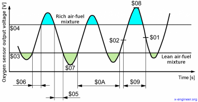
I should've provided this picture of what the PCM checks during Mode 5 O2 Sensor Self-Checks (we don't see most of this unless access thru a very high level OBDII tool........but the pertinent parts that affect Cat CE Ratio results thru both front\rear O2 sensors are provided thru Mode 6 PCM Self-Checks):
OBD-Mode-05 Oxygen Sensor Self-Check Test Diagram.png
As you can see, the PCM can maintain engine AFR thru the O2 sensor switching between the $03 to $04 lines (this is the RTL\LTR transition--rep'd by $05\$06--w\ the $01\$02 450mV cross current mid-point).....anything in between the 2 RTL\LTR lines is considered stoich), while anything outside of these 2 RTL\LTR lines is considered either rich or lean......which is what the PCM uses to monitor\maintain Cat CE Ratio results thus are 2 different aspects of the same NB O2 sensor operation.

$03 for Ford is 300mV......any amplitude amount & time spent below this line ($07) is lean & the amount of lean can be extrapolated. $04 for Ford is 600mV.....any amplitude amount & time spent above this line ($08) is considered rich & the amount of rich can also be extrapolated, thus the PCM can actually adjust this by changing the front O2 sensor's amplitude switching range in accordance to what it reads from the 2 rear O2 sensor's amplitude amount & time spent below 300mV ($07) to try to maintain the cat's in the optimum treating capacity\thermo area.......w\ very minimal effect of\to the engine's AFR control in the center between the 300mV\600mV lines (rep'd by $01\$02 for $09).

The amount of cat controls the PCM can manage is dependent on the amplitude range designed into the front NB O2 sensors at time of manufacture. Ford adopted 2 NB O2 sensor operational specs as compatible w\ their SO PCM's....NGK spec (0 mV to 1,000 mV amplitude range) & Bosch spec (200 mV to 800 mV amplitude range) but since Ford actually used NGK 22060, 22500 NB O2 sensors during the 05-10 MY S197 manufacturing period, the SO PCM's are factory-tuned to the NGK spec (as well as NGK heater circuits which are much hotter\heat up far faster than Bosch's thus the PCM's are tuned to use much lower heater duty cycle settings.....this is what causes Bosch spec'd NB O2 sensors to have trouble operating w\ 05-10 S197's.....the heaters don't get the elements hot enough, quick enough thus throws off the O2 sensor operations in addition w\ the narrower amplitude switching range of the Bosch units) thus tend to not play well w\ the Bosch 15717 front NB O2 sensors (which Ford is currently using as factory replacements) unless the tune file is reworked to properly use the Bosch spec\heaters......which a lot of tuners don't mess with (my prior tuner included).

I discovered this after the fact after going thru Jeff Evans HPTuners Ford Mod Motor tuning training courses in which he recommends to change the O2 CL settings to accommodate both specs.....so I realized I threw away a good set of Ford F85F-G9444-BD NB O2 sensors (based on the Bosch 15717 NB O2 sensors) that I tested as bad prior my tuning days due to the tune file being left in OEM setup which favored the NGK 22060\22500 NB O2 sensors specs\heater design. This is now fixed in my tune file going forward so I can actually use both NGK\Bosch spec'd NB O2 sensors properly, but the way the PCM is controlling the cats thru these NGK 22060\22500 NB O2 sensors is what will keep me using them in the future.

The Ford engineers who designed all this are some very sharp\smart folks indeed.............

Posted this for informational purposes.
 

GlassTop09

Senior Member
Joined
May 24, 2019
Posts
1,142
Reaction score
525
Location
Farmington, NM
FYI..............

After getting all lined out tune wise w\ my car I then ran a test to see how much a fuel stoich AFR tweak will change the catalyst CE ratio calcs running off the same cats. Since, when looking for the fuel stoich AFR numbers for E10 fuel, I ran across 2 different numbers given (14.08, 14.13) so I used these for my little test as follows, using the exact same drive cycle route to bake in as much of the same environmental\elevation\grade changes, etc, as I could...................

Last Cat CE ratio results for E10 (14.13.........numbers derived off EPA's spread sheet for fuel stoich AFR w\ 10% ethanol content):
B1 @ .090
B2 @ .090

I then changed this in tune to 14.08 (all else the same including the fuel in tank........only change made in tune file) then ran drive cycle to complete IM Readiness then read Mode 6 using my Foxwell NT301 scan tool:
Cat CE ratio results for E10 (14.08)
B1 @ .238
B2 @ .297

Results show the cats have degraded in efficiency........that were showing to be very high efficiency prior.

I then changed this in tune back to the same 14.13 (again all else the same including the fuel in tank) then ran drive cycle to complete IM Readiness then read Mode 6 using same scan tool:
Cat CE ratio results for E10 (14.13)
B1 @ .043
B2 @ .031

Notice that the cat CE ratio results went back to the same area\region of catalyst efficiency when using the fuel stoich AFR of E10 (14.13) but cat efficiency went south when using fuel stoich AFR of E10 (14.08). This result shows that 1 of these fuel stoich AFR's isn't rep true E10 fuel which the PCM read fine, calc'd fine, NB O2 sensors picked up Ok but in the STFT+LTFT correction caused the PCM to calc more free O2 into exhaust that was too much for the amount of free HC & CO in exhaust to treat........either thru the fueling corrections to PCM MAF calcs or thru the EVAP purging since PCM is using the STFT's to determine EVAP canister emptying or thru the PCM calcs to determine the amount of free O2% to send into the cats off the STFT switching readouts to treat the HC & CO in exhaust.......enough that the front cat substrates couldn't use it all up thus a larger % of free O2 got thru cat substrates causing the rear O2 sensors to increase switching rate relative to front O2 sensor switching rates so PCM calc'd cat CE ratio results higher or cat is degraded in efficiency.......but they aren't degraded in any way (as evidenced by the reset of fuel stoich AFR back to 14.13.......all returned back to the same region\area of high cat efficiency that they started from).

This is from making just a .05 AFR change in the fuel stoich AFR used in tune only w\ the same E10\91 oct fuel in tank across all testing.

Back checked the 14.08 E10 fuel stoich AFR & it's ethanol content is 10.8% or closer to 11% ethanol instead of actual 10% ethanol (14.13) based off the EPA Excel spreadsheet calculations for this (Jeffery Evans @ EPA built this Excel spreadsheet to be able to calc a fuel stoich AFR of unleaded fuel based on % ethanol content found in it).

Found looking thru other tune files that in 2010, Ford started using the E10 14.08 AFR in the '10 GT500 & from 2011 on in all engines as std fuel stoich AFR but our lowly 05-10 V6's & V8's (includes 07-09 5.4L SC'd GT500) were left w\ the 14.64 E0 (really 1% ethanol) fuel stoich AFR in tune w\ no TSB's to get it corrected in tune for the current E10 std fuel.

My 4.6L V8 as currently equipped\tuned, loves the E10 fuel stoich AFR of 14.13, not E10 14.08 AFR as far as emissions is concerned........w\o any loss of any base tuned performance in OL or CL.

Just a sample of what could be done if a 5-gas exhaust analyzer was used to tune modded engine's CL operations for emissions compliance while still maintaining hi OL power tuning w\ these SO PCM's on an engine being used for dual purpose street\strip\track usage.........

I found all this very neat info to know\use going forward.

Posted for informational purposes.
FYI...........................

While waiting on some hardware to arrive so that I can get my Dummy OBD Relocation harness installed (ordered some black anodized M6 x 20mm bolts w\ washers & trim covers along w\ a black OBDII port cover to mount my relocated OBDII port to a bracket I made out of aluminum to mount this port next to the passenger center console dash trim panel under the glove box so all this will blend into the black dash & stay tucked close to dash so it's not very noticeable at 1st glance......should all be here in AM according to tracking info.....couldn't find any of this type of hardware in town anywhere so I had to hit up Jeff Bezos....).

I was looking thru my tune file again & once again I found yet another set of files where the map scaling had been altered from OEM.....this time they were the KS cyl threshold sensitivity maps & the knock retard max advance\retard maps....these 2 section's map scaling's are also synched to each other so thus Ford engineers had tuned all this to work in synch w\ all the other maps OEM X-Y axis scaling they worked out in all the other sections to interface\intermesh together......this enhances the PCM's ability to interpolate setting transitions much faster thus enhances overall engine responsiveness by reducing total PCM overhead. So, I reset the RPM scaling of both these sections to match the OEM RPM scaling as worked out by the Ford engineers, just as I have already done to all the other maps prior these so at this time, I have reset all the map scaling (the majority of all map scaling changes I've found were made to the RPM scale--X-axis--in my tune file.......for the life of me I can't see or define ANY viable reason as to why change these in a tune file that is going to be used\remain in a NA engine configuration.....especially a SBE NA engine. FI usage OTOH, is a perfectly viable reason) in all maps in my tune file back to OEM stock X-Y axis scaling so after today this is all finished.
While I was in there, I got a thought to go back & retry the Ford given fuel stoich AFR setting of 14.08 for E10 unleaded fuel since I have made quite a few changes to tune since I ran the test back in April to see if I would get the same results I did back then or would get a different result, so I made this change in tune file as well & flashed tune revision #32a in this morning. Datalogged the initial startup as always & all went as usual....but I did note the PCM actually making low scale amplitude adjustments (lean) to lessen the amount of lean O2% sampling it sent into the cats due to the cats being a little slow to light off.....my read is this was due to the fuel stoich AFR setting change......you could clearly see the low amplitude numbers creeping up lessening the amount of free O2 sent into the cats to then see the cats respond thru the rear O2 sensor voltage climb up to exceed 825mV as well as noticing the B1\B2 LTFT numbers didn't move as far -% as prior so PCM was reacting to the NB O2 sensor STFT+LTFT feedback from the burned E10 unleaded fuel using this 14.08 fuel stoich AFR setting in the EQ Ratio Lambda 1.0 equation.

Took car out on initial DC on same 37.6 mi route in same direction\manner as all prior runs then checked all data as follows (all I\M Readiness monitors except EVAP successfully completed on this DC):
Mode 6 Cat CE Ratio:
B1 @ .070......idle LTFT @ -2.3%
B2 @ .066......idle LTFT @ 2.3%
CMBT @ 1,322*F
Well, we can see that all the tuning changes I've made\done in tune file since the April tests were run have certainly agreed w\ the 14.08 fuel stoich AFR correction to EQ Ratio Lambda 1.0 (or we're starting to get "winter blend" E10 91oct unleaded fuel in the fuel tanks at the ConocoPhillips station where I filled up the last 4 times & is my preferred E10 91oct unleaded fuel to run). The current weather may be playing a part (much cooler, more dense air) but whatever the reasoning is, the results clearly show the tuning is now liking the 14.08 fuel stoich AFR setting in tune file so I'm gonna leave it in for a while to see where it all goes. Engine is running very well & sounds very healthy (I stepped into her & pushed her to 5,500 RPM's thru 4th gear & engine never stopped pulling & exhaust note was sounding very solid, clean & steady so all seems to be in line.......1 of my reasons to retry the 14.08 fuel stoich setting was to fatten the fueling up a little more w\o messing w\ the injector data.....this puts the OL PE corrected AFR at current .85 Lambda to 11.968 AFR & at current .87 Lambda to 12.25 AFR........w\ 14.13 this was 12.011 AFR at .85 Lambda & 12.293 AFR at .87 Lambda so hopefully no knock is occurring w\ this much extra fuel cooling the combustion chambers). I'm hoping I can now reset the OL PE fuel map to .88\.90 Lambda which will put the AFR back in the 12.390\12.672 AFR range......close to where this was using the erroneous 14.64 fuel stoich AFR setting for E10 91 oct fuel (at current .85 Lambda w\ 14.64 fuel stoich was 12.444 AFR\at current .87 Lambda was 12.737 AFR.......all off a calibrated WB O2 sensor in OL tuning so I should be able to do this w\o issue.....just need a WB running to make sure of it).

If all goes well & all my hardware comes in, I should be running VCM Scanner datalogs sometime tomorrow......if datalogs show no knock sensor activity pulling timing, I already have the next revision #33 ready to flash in that has all knock sensor cyl threshold sensitivity map data reset back to '08-'10 OEM settings (noted that current settings for all cyls are detuned slightly from OEM settings & from Jeff Evans Ford training courses he states the only reason to change any of these settings from the Ford-tuned OEM settings is from either running a built engine w\ forged pistons\rods\crank\aggressive camshafts or FI-equipped engine due to increased engine noise output.....not a SBE engine using stock pistons\rods\crank using fairly mild camshafts in NA config) to then see if the engine still shows no knock during part throttle\WOT.....which would verify the training & put my engine in much safer territory if found to be true.

Then I'll be ready to start some actual tuning on her going forward.
 

GlassTop09

Senior Member
Joined
May 24, 2019
Posts
1,142
Reaction score
525
Location
Farmington, NM
FYI.................

Made my 1st official VCM Scanner driving datalog on ole girl this evening (no large throttle sweeps or WOT hits yet, just normal stop\go driving up to 55 MPH hiway speeds....mainly to test VCM Scanner graph layouts I made to ensure they all work properly.....including the "Horsepower Dyno" graph to use to record WOT HP\TQ output).

All went well.....recorded approx 1 full hr of driving. All graph layouts I set up work as intended so all data recorded just fine.

The big takeaway from this 1st datalog is that this engine is under optimized below WOT.......all 8 cyls knock sensor outputs are screaming for more added spark timing in the .10 thru .70 load drivability area (running fully capped out BKT\BKT corr\knock max advance timing right at the .5*-1.0* spread below MBT\MBT corr timing across the board.....right where I initially set it all up front) thruout the RPM range. Air\fuel is dead on point w\ the 14.08 fuel stoich AFR in EQ Ratio Lambda 1.0 (running between -1% thru 1% across the board in CL-Normal Mode......can't get any better than this) so she does indeed have more in the tank to get. Running VCT load% cam retard is avg'ing in the 22*-28* range.....not even using the full 30* of cam retard except in initial low speed accelerations so it appears that the revamped VCT load% 30* cam retard mapping matched to the Lunati's GI adv cam EVO timing point is gonna be more than enough & is verifying all the work done in the tune file up to now as valid......just need to fully optimize the BKT\MBT VCT spark advance adder maps. The FP 62mm TB--due to the remapped PTA\EA maps--isn't being opened no more than 8%-10% w\ APP at 25% so this is gonna be interesting what I find during WOT hits........a LOT more TB thruput area for airmass flow available.

Using the BKT VCT spark adder\MBT VCT spark adder maps to fine tune spark timing advance in conjunction w\ VCT load% cam retard matched to the camshaft's adv GI timing points is verifying Ford's coding to be the optimum way to optimize this 4.6L engine's HP\TQ output across the board......using VCT operation to add any additional BKT spark advance timing instead of trying to force it all thru base BKT spark advance tables.....like for a 2V. Gonna be looking to apply all this during WOT as well.

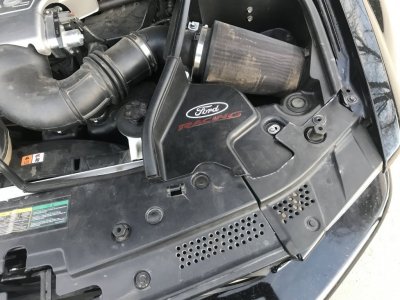
Running IAT's were in the high 50's*, low 60's* (running calc'd AAT was 43*F) so engine is getting a LOT of very cool airmass down it's throat......verifying the mods I made to the left side of front radiator cover & left radiator extension cover (drilled 1\4" chamfered holes in section of both covers that sit in front of the Bullitt CAI's air entrance to allow direct air flow into CAI from the front side of the rad core support while at the same time act as a screen to keep trash away from air filter so only dust makes it in--running a dust sock over the K&N E-1997 Bullitt filter to keep most of this out while not impeding airmass flow thru it.....was dyno tested\verified).

Plan on making a couple of slow throttle sweeps to 6,000 RPM's in 3rd gear soon to check TB out then if all looks good, make a couple of full WOT hits to the limiter in 4th gear to get the rest of the info I need before starting to make spark timing changes (need to see if the knock sensors stay quiet here like they are currently doing......want to reset all the knock threshold sensitivity maps back to OEM settings. KS #1\KS #2 voltages are running very low.....highest I noted was in the low 3xx range so we may be well suited to return all knock threshold sensitivity map settings back to stock......a very good thing).

Pulled Mode 6 Cat CE Ratio results as follows:
B1 @ .117......idle LTFT @ -3.9%
B2 @ .094......idle LTFT @ 0.0%
CMBT @ 1,001*F (this is off......idled too long after backing into driveway shutting the laptop down before shutting car off to preserve the actual CMBT settings so cats cooled down......most likely was between 1,275*F-1,322*F range). Showing a much slower rate of increase.......this is a good sign......gonna keep an eye out on this so might make a few more DC's before flashing in updated revision just to see where this levels out.

So far, so good.
 
Last edited:

GlassTop09

Senior Member
Joined
May 24, 2019
Posts
1,142
Reaction score
525
Location
Farmington, NM
FYI.......................

I ported all VCM Scanner datalog, layout & channel files I used in my laptop to my desktop computer this morning to make use of the 27" monitor for viewing ease (eyes are getting more tired......even w\ glasses on......gotta go get retested for new glasses) running playback in VCM Scanner (I have both VCM Editor & Scanner software loaded up on my desktop computer as well, but license is tied to the laptop so can't save\flash anything modified on the desktop) to view yesterday's datalog run.

Now I can see\manipulate the datalog much easier on this computer using my trackball mouse.

Everything is looking good w\ a little TB tipin detonation ctrl kicking in on initial TB movements (FP 62mm TB) on larger initial acceleration inputs (such as initial TO in 1st gear, shift into 2nd gear then gone while shifting into 3rd gear & up) only due to the initial inrush of airmass causing a slight leanout moment then all goes away......all within a few seconds. Doesn't have any effect on engine AFR, so a little transient fuel gain application should fix this (all stock settings set up in tandem w\ the OEM 55mm TB so I'm gonna look at the '10 GT500 stock tune's transient fueling setup--FP 60mm TB--to see if I can use any of it w\ my FP 62mm TB, otherwise trial & error to dial it in). Everything else in the log looks very good so the only item left to look at for now is slow throttle sweeps in 3rd gear to 6,000 RPM's to check TB operation\rotation then a couple of full WOT hits in 4th gear to limiter (I reset my limiters to focus on primarily using the TB thus a "soft" limiter instead of using fuel\spark cut to reduce stress on the cam timing--chains, phasers, guides, tensioners, oil pump gears--components) set @ 6,500 RPM's (OEM for Bullitt 4.6L's) to see how all this is currently shaking out (noticed that all cyl KS threshold sensitivity settings less than .50 load is still OEM so all the KS activity I saw in my current datalog is using OEM settings.....)......would love to see all WOT BKT spark advance timing go full w\ full knock 4* advance timing added.

This is the part that's gonna take the longest for me to do.........the datalogging won't but the going thru the data to discern what's what then make the changes in tune\reflash to then do it all over again until it's done, since I'm a newbie.

Getting there!
 

GlassTop09

Senior Member
Joined
May 24, 2019
Posts
1,142
Reaction score
525
Location
Farmington, NM
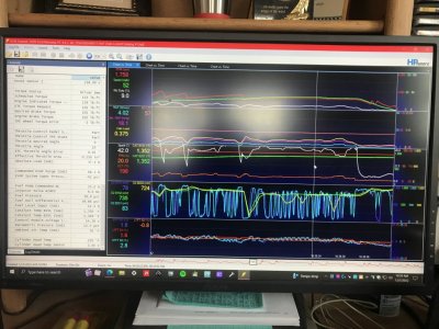
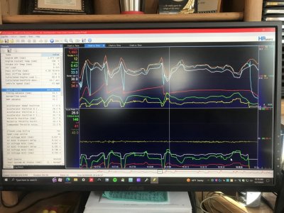
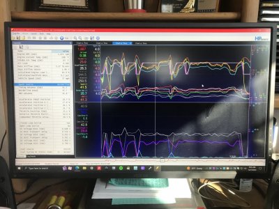
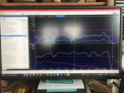
Here are provided some shots of my engine operations during the normal driving datalog as I have the datalog layout file currently configured in VCM Scanner:
VCM Scanner MAF Catalysts O2 Sensors STFT & LTFT.JPG VCM Scanner Horsepower Dyno.JPG VCM Scanner Knock Sensors VCT.JPG VCM Scanner Lambda EVAP.JPG
You can clearly see the PCM, in the KS\VCT picture, is maxing out all base BKT\BKT VCT Spark Advance Adder & KS Max Advance timing against the base MBT\MBT VCT Spark Advance Adder timing when running engine airload is above .25 (threshold setting where PCM either looks at\ignores the KS's) thus is capped......meaning the engine can use even more spark advance timing applied w\o knock.
But the $64 question you have to ask yourself is......do you really NEED IT? If you look at the Horsepower\Dyno picture, the PCM is showing the necessary wheel HP\TQ needed to maintain the engine's current RPM's\MPH of the vehicle thus is being controlled, so you DON'T need to add any more timing to the BASE BKT\MBT Spark Timing maps (this is not where you can make the most use of any additional spark advance timing) BUT YOU CAN add more spark advance timing to both the BKT\MBT VCT Spark Advance Adder maps so the PCM can use it thru VCT operations to enhance engine acceleration as you can see the PCM, on any called for acceleration, will use VCT to retard the cams & will also apply any extra spark advance timing thru the multi settings put in these BKT\MBT Spark Advance Adder maps to enhance the base BKT\MBT timing maps so both are enhanced together (this enhances TQ Management as well as BKT) THEN looks at the KS's when airload is above .25 (or wherever the threshold is set to in the tune.....OEM is set @ .30 load) to see if any additional spark advance can be added from KS activity to the already enhanced BKT spark advance timing & stay just below the enhanced MBT spark advanced timing across the board at its max settings as long as the KS's say so, thru out the rest of the engine operations where the PCM deems it to be necessary or not.....IMHO, this is the optimum method w\ this 4.6L 3V where any additional spark advance timing is best used......not in the base spark timing maps & puts the PCM in full command of all of this thus isn't "locked out". This way TQ Management thru MBT timing as well as engine's BKT timing is always optimized wherever the PCM deems it to be......safely as well as reliably.

Thus, IMHO the max use of VCT is the golden ticket.......but these BKT\MBT VCT Spark Advance Adder maps are being overlooked\underutilized\disabled by a lot of tuners..................IMHO, a big mistake.

This is where "easy" is not "better"......................

Also, IMHO, even if FI is used. Yes, they're more tedious to set up\adjust but they're also the far & away best method to apply additional spark advance timing thru VCT usage which puts the PCM in full control of all of it........Ford engineers knew this & is why its coded to operate as such.....that is, if we actually use it the way Ford set it up to be used.

My engine is currently using max BKT\VCT\KS combined spark advance timing that is .5* thru 2.5* more advanced than the "locked out" MBT\VCT spark advanced timing that my prior tuner was using in his tune mapping in the same drivability area of the tune vs mine & the engine is still wanting\can use even more........this is just showing how underutilized this engine's HP\TQ is thru the .10 thru .70 load operating range which is good for MPG & emissions.......where most of us actually live when driving around on the street........and where we're actually JUDGING most tuner's work, not the PEAK dyno HP\TQ numbers as these WOT peak HP\TQ numbers just cannot accurately represent any drivability performance of these 3V's (or Coyotes as well) when VCT is being used (w\ these 3V's using SO PCM's, peak dyno numbers are in OL PE Mode when WOT is applied where the PCM is operating mostly manually w\o any airload or fueling correction, whereas drivability is in CL-Normal Mode where the PCM operates fully dynamic--can correct for most all parameters--under part throttle operation......thus apples to oranges in comparison).

A smart tuner IMHO should actually DRIVE any vehicle & datalog it after tuning it on the dyno is finished to check the drivability performance BEFORE giving the vehicle back to the customer to make sure that you've covered it all, but how many tuners will take the time & do this? Then at the same time, how many customers will PAY the extra money for the tuner's time (remote tuners as well) to do all this?

In the end, IMHO the best move you can make concerning these 3V's is learn\tune yourself.
 
Last edited:

MrBhp

Senior Member
Joined
Sep 12, 2013
Posts
1,255
Reaction score
1,038
So, there is a direct correlation (adjustable) relationship between cam timing and spark timing? I did not know that. I just figured they were completely separate entities.
I would really enjoy tuning mine myself. I bet I could blow it up in record time.
 

GlassTop09

Senior Member
Joined
May 24, 2019
Posts
1,142
Reaction score
525
Location
Farmington, NM
Ready to call the 'tuning addict support line' yet?
Actually from running this datalog & looking at the data, outside of a little accel transient fuel gain adjustment to clean up the initial 62mm TB opening air inrush causing a small slight lean out for a second or 2 & a little more spark advance multis added to both BKT\MBT VCT spark advance adder maps to get a little more crisp acceleration response, all the rest is golden outside of checking WOT performance to see if it is truly optimized.....so no I don't think I'll need any therapy to talk me back off the ledge, hehe.

Just will be 1 fully happy camper while behind the wheel & didn't have to argue w\ anyone to get it here.

Just a good feeling to see all your studying, learning, understanding then application efforts showing the fruitful results you expect\want to see, hear & feel from your steed.........what makes you want to drive it all the time.

:driver:
 

GlassTop09

Senior Member
Joined
May 24, 2019
Posts
1,142
Reaction score
525
Location
Farmington, NM
So, there is a direct correlation (adjustable) relationship between cam timing and spark timing? I did not know that. I just figured they were completely separate entities.
I would really enjoy tuning mine myself. I bet I could blow it up in record time.
Yes sir it is but it is kinda tedious to apply it well & you'd need to have a very good understanding of the cams adv GI timing points & engine crank degree\piston position relevance along w\ good use of a calculator to apply some math to then set it all up to reduce the amount of constant twiddling\fiddling to find the sweet spots.

I've always loved mathematics\the sciences in high school, so this was really fun for me in a nerdy way.........

That's the mistake a lot of folks are making w\ this 4.6L 3V (even after this engine is out of production so thus should be a fully known platform by now) by not using these BKT\MBT Spark Advance Adder maps adequately as these maps are tied to VCT cam timing operations to account for the retarded cam IVC timing to regain the lost dynamic cyl compression\pressures thru using extra spark advance timing in addition to the base BKT spark timing when the PCM is retarding the cam EVO timing to optimize power stroke TQ output from this VCT DEPS (dual equal phase shifting) system since this engine is using SOHC cams w\ both intake\exhaust lobes on the same camshaft.
If you're using the base BKT\MBT spark advance timing maps alone, you can never make up adequately for the cam IVC retard thus lost cyl static compression pressures in NA config from VCT load operations (you could use extra boost pressure to try to compensate if FI, but this is only a mask at best) & you've taken the PCM out of the equation thus you only have the KS's left to use......thus you're leaving HP\TQ on the table, regardless of the cams being used.

Ask yourself this question......why would you want to tune a 4.6L 3V w\ VCT like you would a 4.6L 2V\4V w\o VCT?
Because it's easier.........................?

Why Coyotes are much more superior since they use Tri-VCT which is a DIPS (dual independent phase shifting) system using separate intake\exhaust cams.......but the same thought processes are needed to fully optimize either setup.

These Ford SO & up PCM's operations are more integrated\interrelated than some realize.
 

GlassTop09

Senior Member
Joined
May 24, 2019
Posts
1,142
Reaction score
525
Location
Farmington, NM
FYI.....................

For the record, if you're tuning yourself or datalogging for remote tuning.....or just datalogging for diagnostics, relocate the OBDII port to the passenger side or somewhere away from the driver side. This Dummy OBD Relocation harness is the bees knees.......very clean install....virtually invisible & makes datalogging soooo much easier & fun.

Now with that out the way, the 2nd datalog I ran showed up a hitch in my tuning that I didn't think was going on.....car has ran very well from the beginning & all seemed to be fine, but this log captured an issue that was tied to this SO PCM switching from CL-Normal Mode to OL PE\WOT when I made a little mini hit up to 5,500 RPM's shifting between 3rd-4th gear shift......the PCM never tried to switch thus was staying in CL-Normal Mode so leaning the fueling out. PCM was trying to keep up & add fuel but wasn't ever gonna be enough thru EQ Ratio Lambda\Fuel Stoich AFR 14.08 staying at 1.0 so engine was slowly heating up (thank fully my Mishimoto HP 3-Row Aluminum Radiator\FP M-8C607-MSVT GT500 Fan Upgrade was more than up to the task......ECT never exceeded 198*F w\ IAT's at 57*F so she was getting rid of a LOT of this extra heat so only had 1 cyl start pulling timing--#3cyl--from all cyls being the full 4* advanced thus riding MBT. Then the COT protection kicked in further brought the cyl temps into check so she saved herself). Didn't stay into her long, just enough to record\capture data to see if all was operating OK so I never knew this was going on until I played back the log. The cats got pretty hot if I must say--1,655*F--so not real heavy, just enough to kick off COT protection & cool em down. So, I once again dodged a bullet w\ ole girl.

Datalogs showed the PCM never tried to get into WOT until right before I let up & never made attempt to switch into OL Accel\Decel Power Demand (Power Enrichment). Noted on datalogs that there was a discrepancy in the APP data between the channel & the graph (channel showing proper APP signal but graph was approx 15.9% off.....had both set up to show %) so I reset both to show data in A\D counts (still showed the discrepancy but I realized my error from looking at this data.......the APP applies A\D counts differently so I had assumed this was similar to how other parts of tune used them so I ended up over calculating my setting for Pedal Position WOT Start......thought I had it set for 35% or 358 A\D counts APP but it ended up being at 41% & with the 15.9% error it never got to the threshold (the 250 A\D count setting my prior tuner had input was actually at 32% instead of the 24% I thought it was set to....). Good thing is thru this exercise, I verified the KS's do work & work very well using Per Cyl application of knock signal instead of Global application as the threshold sensitivity maps are currently set up so I can leave all that as is (so little loss of power thru 1 cyl knocking that you couldn't hear\feel that it was happening........this is a must add for these 3V's & is available in all SO strategies from 05-10 MY.

So, to make a quick fix I pulled up my prior tuner's copy I saved & used it to reset all this & the TB PTA\EA mapping (put back to the OEM 55mm TB maps) in ETC control as well as the OL Fuel TPS Threshold map (known working prior to test) along w\ the 500,000 IPC Wheel TQ Error setting & flashed rev #32c this morning & ran a full datalog from 1st start thru the full initial DC route back to my driveway........found this fixed it all. Made another 4,500 RPM 3rd-4th shift w\ APP to the wood during the DC........can report all is operating as expected now w\ the surprise of the PCM in OL\Power Demand adding the full 4* knock spark advance thruout the hit w\ EQ Ratio 14.08 E10 Fuel Stoich AFR\Lambda 1.0 control setting fueling at the .85 Lambda (thus 11.968 actual AFR) off OL base fuel map w\ 11* of VCT retard (load @ .71 so .77* extra spark advance timing added to base BKT spark timing of 27.70* so 28.47* + 4* = 32.47* & engine never sneezed & PCM never pulled any of it out while RPM's were climbing until I let up) so all checks out operational-wise now. ECT was steady @ 198*F & IAT's were a crisp 37*F--calc AAT was 34*F......she's getting some very cold air down her snout thru this FoMoCo Bullitt 83mm CAI from my modded front rad shield & CPC rad extensions.....allows cold ambient air entry from front side of core support thru grille\under left front bumper beside headlight housing:
IMG_0653.JPG I am going to have to make some setting changes in tune to compensate for this to keep PCM from shoving more fuel in due to low IAT.......my low 0 deadband IAT settings is 30*F.

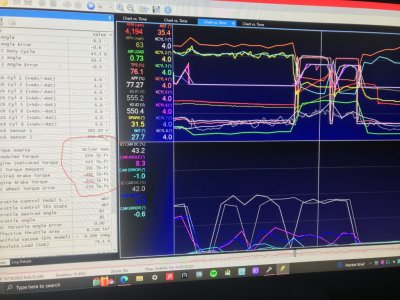
So now that this is rectified, I'm gonna put the FP 60mm TB PTA\EA mapping back in tune then fully tune these to match the FP 62mm TB's actual PTA\EA sizing. The IPC Wheel TQ error control is verifying that this 55mm TB PTA\EA mapping is causing the PCM to calculate TQ output too low at WOT (PCM uses SD tables to calculate ETC SD airload to then compare to LWFM table air load calcs.....which are lower than the airload calcs from actual MAF lbs\min airmass off the 62mm TB's actual PTA\EA area thus shows up as IPC Wheel TQ Errors........so PCM is lowballing this) ......
InkedIMG_0655_LI.jpg Yeah, I know the engine RPM's aren't at max yet (6,500 RPM limiter) but unless TQ Management can actually apply more of this to the wheels she'll come up short due to the lowballed SD calcs thru ETC control from the wrong TB PTA\EA mapping......something I was fearful of happening once I learned how all this actually works & ran some calcs on several dual TB PTA\EA area. I can already feel the accel punch loss off the line due to this right now (still good but has dropped off some). Some of this can be gained back thru using the BKT\MBT VCT spark advance adder maps (note how they're enhancing TQ Management's TQ calcs thru the base MBT\MBT VCT adder spark mapping.....this is the max TQ application thru Ford's OEM-tuned Indicated Engine TQ mapping & SD mapping which includes the ETC control mapping to predict the MAF calc'd airloads, so as long as the airload\fueling is there & she can tolerate the cyl pressures, she should be able to max out somewhat higher than 352HP\320TQ......especially from making all the tuning corrections that should enhance the TQ output (injector CA ref set to Lunati cam's adv IVO timing point to improve fuel atomization\swirl thru intake valves, reworked BKT\MBT VCT spark advance adder mapping tied to VCT making full use of VCT cam timing advantages, 62mm TB PTA\EA remapping, 8 ga awg FP wire mod upgrade to stabilize\increase fuel delivery, reworked VCT cam timing to crank\piston positioning to optimize TQ output, 14.13\14.08 E10 fuel stoich AFR correction for EQ Ratio Lambda 1.0 fuel control, MAF Adaption to fine tune fueling from MAF corrections as well as NB O2 sensor STFT+LTFT correction, tighter O2 TD timing settings to enhance fueling accuracy thru LTH's & a host of other little tweaks) to some point past this, especially during this winter w\ all this cold air to ingest.

Gonna start the process in the AM when I flash in rev #32d.......have already finished setting up the ETC TQ Error graphs to start the process of recalibrating these PTA\EA maps to fit this FP 62mm TB so will be flashing her in the AM to kick this off. The full WOT tuning will be somewhat delayed (will have to disable COT protection to do WOT to keep the cat temps from interfering (running cat temps are bumping up against 1,500*F (1,480-1,490 range) right now just from normally driving her around under 70-80 MPH......the fueling is a little fat as well so will get hotter once I start leaning her out to get her in the 12.6-12.8 sweet spot range--need to get my Zeitronics ZT-4 Dual WB controller installed\wired up sometime in the near future.

Slowly getting there.

Stay "tuned"................

PS edit--Almost forgot......all 7 I\M Readiness monitors completed for the 2nd consecutive time since being able to do all flashing, 1st startup idle training\learning then full initial DC w\ 60-40 Misfire Monitor training included in 1 shot. Mode 6 Cat CE Ratio results:
12-9-22 off rev #32b (Dynamic Airflow setting change to 8.90 to enhance transient fueling to attempt to fix the Throttle Tip-In Detonation Ctrl kicking in..... didn't stop it--this is disabled in tune but is still being applied by PCM due to the 62mm TB's faster response using the Ford 60mm TB PTA\EA mapping & upgraded\added BKT\MBT VCT Spark Advance Adder timing):
B1 @ .148....idle LTFT @ -3.1%
B2 @ .145....idle LTFT @ 0.0%
CMBT @ 1,521*F (little hot)

12-10-22 off rev #32c (Reset Dynamic Airflow back to stock 10.90, fixed all ETC control & OL mapping to correct CL\OL transitioning.....this did mostly fix the Throttle Tip-In Detonation Ctrl kicking in as well, but 62mm TB response suffered from using the Ford 55mm TB PTA\EA mapping):
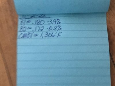
B1 @ .137....idle LTFT @ -3.9%
B2 @ .172....idle LTFT @ -0.8%
CMBT @ 1,483*F (little better but not much better)
 
Last edited:

GlassTop09

Senior Member
Joined
May 24, 2019
Posts
1,142
Reaction score
525
Location
Farmington, NM
FYI....................

Revisited the TB PTA\EA mapping relation to ETC TQ modeling based on ETC calc'd air load% per TPS angle% vs actual MAF airload% off same TPS angle %............I may have stumbled upon something that may demonstrate more importance of a larger TB concerning the use of it's correct PTA\EA mapping data in ETC control, not only w\ throttle tip-in & acceleration response but also top end HP\TQ from the calc'd air load% difference @ 82% TPS angle (WOT) between ETC calc'd air load % vs actual MAF airload% for TQ modeling.

I looked again at the PTA\EA mapping given for an '09 OEM 55mm TB in sq\in area in tune file (4.2 sq in).....this doesn't equate (comes out as essentially only 57% of the full sq in area of a twin 55mm TB--I calc'd this total sq in area to be 7.33 sq in) so if my math is right, this is a potential cutting of the calc'd TQ output potential at WOT thru the ETC TB modeling based on TB sq in area given to calc air load% @ 82% TPS angle for max TQ application @ .90\.10 load or WOT. To back check my calcs, I pulled the same given sq in area for the OEM '10 GT500 FR 60mm TB (8.76 sq in) PTA\EA mapping data then ran same calcs using same equation & came up w\ 8.74 sq in (FR 62mm TB is 9.35 sq in or is .61 sq in larger.....by contrast the 4.2 sq in given for 55mm TB is 4.56 sq in smaller than 60mm TB or 4.79 sq in smaller than 62mm TB) so my equation I used jives thus shows the given sq in area in tune ETC TB PTA\EA mapping for a twin 55mm TB is not correct thus is under calc'ing ETC TB airload% vs MAF airload% for TPS of 82% or WOT for TQ output so PCM falls back on ETC TB airload% calc for TQ instead of actual MAF airload% at same TPS angle%. Ford has to have done this intentionally to cut engine output to maintain around 80% VE (even though the MAF calibration max airflow vs voltage table of 39.809 lbs\min @ 5.0v is just over 100% ideal VE of 4.6L engine's displacement @ sea level or 14.7 psi atmos).

So a WOT datalog of ETC TB airload% calc vs MAF airload% calc should prove this out either way....... If MAF airload% is not rep of at least 36.28 lbs\min but is around 29.09 lbs\min (between 4.38v-4.42v MAF sensor output) @ WOT then it proves Ford undercut this 3V's potential thru the ETC thus even a 55mm TB may need to be remapped in tune to get full ETC TB airload% calcs thus full WOT HP\TQ out of these 4.6L's (this 4.2 sq in area mapping used w\ a 62mm TB creates an even larger IPC Wheel TQ error problem which might have PCM closing TB angle% even more to "correct" MAF thus throws WOT airload off--chokes airflow thru engine--to read same as choked off 55mm TB from same PTA\EA mapping data used in ETC TQ modeling..............).

Lets hope I'm wrong on this but my math ain't wrong & PCM uses this math in ETC TB airload% modeling to run its TQ calcs...........SO PCM calcs all as a measure of TQ output in load% vs RPM's..........

I've also witnessed several sq in area numbers given (from 4.2 to 4.9 to 5.1) for the same 55mm TB in several different MY & marks of Ford 05-10 V8 Mod Motors SO PCM tune files (4.6L\5.4L) used in Mustangs.......hhhhhmmmm......

Interesting.........................now do y'all understand why I do the math myself to back check\verify what I see to either be proved true or false & if found true\false to find out why................doubt this would be the result of an engineering mistake by Ford engineers if proved true, but very easily be a result of Ford corporate management decisions made based on several mitigating factors at the time of manufacturing........performance output not being 1 of them.

Just thought I'd put this out here for consideration sake............
FYI......................

Here is a copy of an automotive engineering study concerning automotive throttle bodies & how they're used within a SD model that I found very interesting. Helped give me a lot of clarity concerning how Ford is using it's version of SD in the SO PCM's thru the TB's to arrive at airmass calcs to then compare to MAF calcs.

Enjoy!
FYI..............................

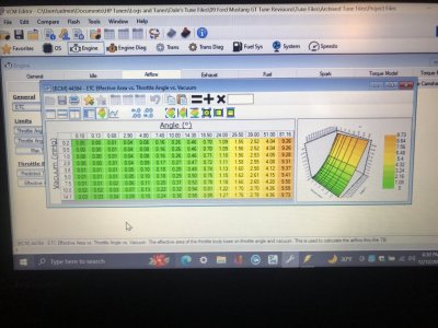
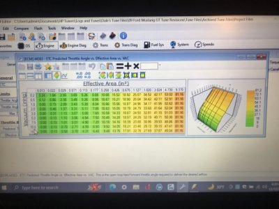
Just got done running datalogged ETC Throttle Error graph data thru the process of updating the tune's TB PTA map data w\ it, making the necessary smoothing to clean it all up & follow the existing map's scaling trending then copy it all into the HPTuners ETC EA Calculator to spit out the new TB EA mapping that corresponds to the captured\smoothed TB PTA map data.....thus corresponds to the installed FP 62mm TB's actual PTA\EA to clean up ETC TB airmass calc's thru SD using the LWFM tables for predictive airmass to use to calc fueling\TQ thus engine output then compares to the reactive MAF airmass calcs using the same TB TPS angle% the ETC control used for agreement\accuracy within a certain acceptable margin of error (very small margin........don't yet know the exact scale Ford used for this.......ain't a member of the "club" to get the inside knowledge yet. So yes, the PCM IS using this to set\control engine HP\TQ output thus IS important that this is properly representing the actual installed TB's internal flowing effective area ID between the butterfly blade and the TB internal throat ID according to the amount of TPS angle open %......IOW's the outer areas around the top & bottom of BF blade to TB throat ID open to airmass flow measured to sonic airmass speed according to baro (outside air pressure) to manifold vacuum in inHg downstream of TB (internal absolute pressure thus pressure drop or deltaP).

Here are provided pictures of this result:
Corrected TB EA Map for Ford Performance 62mm TB.JPG Corrected TB PTA Map for Ford Performance 62mm TB.JPG
Looks like the calc'd result of 9.35 in2 I came up with back in post #249 for a FP 62mm TB's max EA in2 area was right in line after all so thus validates my thinking\reasoning on what I found back then that what Ford was doing concerning these maps in the tune files has some merit........so the OEM 55mm TB's actual in2 area is larger than what is given for it in the OEM tune files thus Ford intentionally under tuned these engines on purpose in more ways than 1......

Wonder how close my calc'd 7.33 in2 calc I came up with for the OEM 55mm TB actually is....................

Posted for informational purposes.
 

GlassTop09

Senior Member
Joined
May 24, 2019
Posts
1,142
Reaction score
525
Location
Farmington, NM
FYI................

A side topic concerning the speedo calibration\correction in these S197's I've discovered while tuning my '09 Stang........

I have gone round & round trying to "correct" my speedo calibration over the last several months thru the PCM using all the methods folks posted in HPTuners forums & elsewhere.......in both directions w\o success. So in frustration, I just reset all back in tune using the correct method (set actual rear gear ratio, actual tire revs\mi off actual tire diameter AND the correct N\V base setting by using the trans in 4th gear which is 1:1 ratio to then divide the engine RPM's by the corresponding MPH as created by the trans OSS from the rear gear ratio\tire revs per mi in use.....I used Gearhead Lite app to do this.......didn't use the car's speedo) so that the rest would be accurate (like the MPG calc in IC based on fuel injector PW use & VSS\revs per mi) & left all this alone.

Now fast forward to now while I'm running driving data logs w\ VCM Scanner, I got a thought to check the speedo as read thru VCM Scanner off vehicle's VSS against my nav's GPS & guess what I found........the VCM Scanner read MPH off the VSS tracks consistently within 1 MPH of the nav GPS read vehicle MPH every time! So, what I setup in PCM thru the tune file is actually tracking accurately!

It is then I realized that the 3-4 MPH speedo offset is actually programmed into the IC......not the PCM, to ADD it to the PCM derived VSS output signal sent to the IC to display it to the manual speedo motor...........so to really fix this right you'd need to access the IC thru Forscan & rescale this to a 1:1 ratio to really correct the speedo properly.

So, I was essentially wasting my time trying to fix this thru the PCM in my '09 S197...........!

The things you find out\run into while tuning your own stuff............................
 

Juice

forum member
Joined
Aug 24, 2017
Posts
4,622
Reaction score
1,904
I bet I flashes mine over 100 times just to get the speedo accurate. Was reading 1/3 of actual speed after the build mt82 vs magnum xl) And cheating the pcm with a gear ratio of 1.79 was causing other issues.
I now use the VID block as ford intended for gear ratio and tire size.
Ps: folks forget the switch in the axle ratio section to use tune or vid settings.

Love to know if it is actually possible to calibrate the IC, as I have not found that setting in the cluster. Mine is only off by 2mph, so I set the speedo to be accurate, and odo reads a few tics lower than actual.
 

GlassTop09

Senior Member
Joined
May 24, 2019
Posts
1,142
Reaction score
525
Location
Farmington, NM
Love to know if it is actually possible to calibrate the IC, as I have not found that setting in the cluster.
I would love to know this as well.........I assumed that this was accessible using Forscan but Ford may have dug this coding in real deep to satisfy the Fed gov concerning speed regs on Fed hiways\roads (only reason I can see why Ford would do it........not on their own prerogative......but I can be wrong).

Might look into this 1 of these days but this is really low on my bucket list right now............
 

GlassTop09

Senior Member
Joined
May 24, 2019
Posts
1,142
Reaction score
525
Location
Farmington, NM
FYI...................................

Have saved the revised TB PTA\EA mapping in latest tune revision #34 (cut spark timing across .50 load thru .60 load rows .50* & across .70 load thru .90 load rows 1.5* in base BKT\MBT spark advance maps to stop knock retard from pulling timing when driving up inclines steeper than 25*grade in 5th gear--saw PCM advancing cams back to 0*--increasing cyl pressures--when going around 45 MPH up grade in 5th gear to increase engine load output in .50-.60 load & to stop knock retard from pulling timing when rolling\stabbing APP into WOT from .70 load on (only had 3 of the 8 cyls start dropping so I cut timing for the moment to protect engine until I can figure out why PCM is so slow to switch from CL-NM into OL-PE\OL fueling when rolling throttle into\stabbing throttle into WOT......hung in CL-NM too long so fueling is leaning out causing the 3 noted cyls to start knocking before the switch......even when I put my prior tuner's settings back in tune........) & flashed in\ran DC & data logged the whole thing (some 14K-16K files so got PLENTY of data).

Fixed the slow speed incline hi load knock w\ the .5* spark cut & almost cleaned up the WOT knock (got this down to only 1 cyl now, but PCM is still too slow to switch into OL-PE\OL fueling........the main problem causing this......).........but the big thing today was just how well the FP 62mm TB operates when it is properly characterized in the tune's TB PTA\EA mapping for PCM's ETC to use it.

This thing is as smooth as glass...... operates smooth but crisp so throttle response is very quick & sharp but the power is smoothly\progressively applied (was getting some false TB Tip-in Detonation Ctrl action momentarily cutting spark timing on throttle blips during 1-2, 2-3 shifts using the Ford tuned FP 60mm TB PTA\EA maps prior rescaling them to fit this FP 62mm TB.....even though this TB Tip-In Detonation Ctrl is "disabled"--not turned off......can't do that, but the RPM enable\disable settings are flipped in tune to "stop it" from applying itself.....from the TB being a little choppy on initial opening rate......new rescaled FP 62mm TB PTA\EA maps rectified all of this).
The IPC WTE's practically vanished until engine had a good load put on it but the highest WTE's recorded were -311 lb-ft during WOT......the vast majority of these were under -60 lb-ft & at idle they were blipping infrequently around 2-5 lb-ft (practically drawing a straight line around 0) so this FP 62mm TB tunes exceptionally well (used HPTuner's ETC EA Calculator) when you actually TUNE it using good Ford-tuned OEM 60mm TB PTA\EA maps as the base maps.

Now if I can resolve the causation of why my PCM is switching too slowly into OL-PE\OL Fueling from CL-NM on APP application, I'll have 95% of my tune file optimized in short order.......outside of WOT (need WBs to check\set OL fueling properly to complete WOT tuning optimally).

So, if anyone wants to use the TB PTA\EA map data I posted in the pictures in post #332 w\ their FP 62mm TB, go right ahead........as usual at your own risk.......but they have been verified to work flawlessly w\ mine.

So, I can cross this off my bucket list as I have actually done it & followed thru on what I said I would do once I did this.

Enjoy!
 

GlassTop09

Senior Member
Joined
May 24, 2019
Posts
1,142
Reaction score
525
Location
Farmington, NM
FYI...................(warning, long posting)

Well folks, I think I've found\discovered a breakthrough (at least for me it is) tuning these SO PCM's.........

Yesterday while going thru my process, saw on a datalog that I had spark timing being pulled when engine went into a low speed, high load situation (like going up a hill >25* grade in 5th gear around 40-45 MPH) & during high load accelerations (such as stabbing WOT or rolling into WOT).....but the only cyls showing this were #3, #5, #6 & #8.....mostly #3 but occasionally the others would show now & then but not as bad as #3 (noted cyls #1, #2, #7 & #4 hardly ever hinted at knock......will get to this later). Tweaked & finally got the OL Fuel TPS Threshold graph settings to synch up w\ the APP counts, TB TBA% & TPS % to get into OL PE\OL fueling in the .60 load & up window on a rolling WOT hit (had no issue on a stabbed WOT hit) so engine would not be leaned out, but the knock was still present. Otherwise, all was good.

So, I thought to myself that I've never ran a datalog on my prior tuner's tune file, so I took his file & 1st fixed the obvious areas in his tune (TB PTA\EA maps to match my FP 62mm TB, injector ref CA set to match my Lunati's GI cam adv dur IVO, O2 sensor TD mapping, fuel stoich AFR set correct to match E10 fuel for EQ Ratio Lambda 1.0 fuel control, proper IMRC Open\Close LWFM maps to work w\ CMDP's, MAF Adaption enabled & improved TQ Management DD TQ Request maps) w\ the corrected ones from my tune file to make a more fair comparison (left all his spark advance BKT\MBT, spark retard, airload VCT load & spark advance BKT\MBT VCT spark adder maps as setup by him alone as well as the rest of his tune file) to get a better comparison & to see if I still get the noted spark timing being pulled the same way as I've noted being done thru my tune file. Got all done, flashed in, ran all idle data logs to allow PCM to relearn all this then took out on initial DC, datalogging it all.

What I found is that I got the exact same spark timing pullout in the exact same operational scenarios w\ his spark advance\retard & VCT mapping as I got using mine, so I knew this was due to an issue with the car. Note my mentioning of this in 1st paragraph.......what I noted was that KS #1's signal (which in tune file's Knock Sensor to Cyl map is sensor #1 which cyls #5, #6, #3 & #8 are assigned to) graphed fidelity is very twitchy in relation to KS #2's signal (which in tune is sensor #0 which cyls #1, #2, #7 & #4 are assigned to) graphed fidelity is very clean & stable thruout the datalogs......these cyls almost never show any knock thru any of the test loading\WOT hits I did during DC's.......so I believe KS #1 is starting to wig out (going on 14 yrs continuous operation......original KS's on engine.......very uncommon for only 1 side of engine to exhibit suck knock action only on 1 bank when both banks are under the same loading) so I'll be picking up a set of these & change them out. I also found that all the learned science concerning a cross plane crankshaft equipped engine design concerning TQ output (that I provided drawings of in this thread) was validated..........engine ran w\ a lot less spunk, especially off the line & during any low-speed engine accelerations due to the airload VCT load & BKT\MBT VCT spark advance adder map settings in his tune file vs mine.......so I can hardly wait to start applying all of this to the airload VCT load maps\BKT & MBT VCT spark advance adder maps during WOT......should be a very good time indeed............

The big discovery that I found was that, even though prior tuner had the knock retard max advance map settings from .10 load thru .50 load & from 500 RPM's thru 5,000 RPM's set at 8* advance, the PCM would NOT ADVANCE the spark timing past the base MBT\MBT VCT combined spark advance setting graph line from the base BKT\BKT VCT spark advance setting graph line when the base BKT was set LOWER than the base MBT less than the 8* knock max spark advance setting (area where the PCM will apply additional knock advance spark timing to the base BKT\BKT VCT combined spark advance timing only), but will apply it up to the MBT\MBT VCT timing graph line itself then stop so the combined BKT\BKT VCT\knock max advance timing NEVER crossed the MBT\MBT VCT combined spark timing graph line, even if the knock max advance spark map settings exceeded the BKT\MBT gap difference.......so the PCM IS CODED TO NOT CROSS THIS POINT ITSELF......if the BKT isn't INTENTIONALLY set up in tune file to be higher than the MBT! This wasn't taught in Jeff Evans HPTuners Ford Mod Motor tuning training videos or mentioned on any tuning site or on HPTuners forums (that I looked thru) at all.............

So, the Ford engineers have already coded this SO PCM to ALWAYS SEEK the base MBT\MBT VCT combined spark timing & not cross over it (to always optimize the engine to this MBT timing when the KS's come online as this is the timing that TQ Management uses to calculate max HP\TQ output in ALL engines operational scenarios) IF base BKT\BKT VCT combined spark timing is physically set up to be lower than the base MBT\MBT VCT combined spark timing (so the PCM can apply\add additional spark timing to the base BKT\BKT VCT spark advance timing based on knock sensor activity)!

Damn..........now I can understand why so many people screw the tuning up on these 3V's.......they don't fully understand how this SO PCM is actually coded to function, thus they treat it like a PCM used w\ a fixed cam in block engine (4.6L 2v\4V or most old school Windsor\Romeo small block or FE\Lima big block). The spark advance maps tuners SHOULD be using to tune this SO PCM to is the BASE MBT\MBT VCT spark advance maps then once finished, copy the newly optimized base MBT map contents into the base BKT map THEN cut the base BKT map settings to be LESS than the newly optimized base MBT map settings (I used a 4* spread) so the PCM will automatically use this area to add additional knock spark advance timing to the base BKT\BKT VCT spark adder (or any other BKT correction to base BKT map) if knock sensors detect no knock right up against the base MBT\MBT VCT combined spark advance timing & STOP there.....regardless of how much extra spark advance timing you put in the knock retard max spark advance map.....so the PCM is doing this automatically.....IF all this is set up properly to start with! The PCM is also coded to automatically fall back to the base BKT\BKT VCT spark adder\corrected spark timing when the engine load drops below the KS load enable threshold setting.....this is seen as the 0* line for KS activity, so any KS activity that occurs within the base BKT spark to base MBT spark timing line is deemed as NORMAL activity.........it's when the KS's cut spark timing BELOW the base BKT\BKT VCT adders\correction line is deemed ABNORMAL thus an engine\component issue!

Now this makes all the sense of what the Spark Advance\Borderline Correction\VID Octane Adjust map is used for in this SO PCM......to correct spark timing (only when ALL 8 CYLS show spark timing cuts at the same time that drop below the base BKT\BKT VCT adder timing line.....thus PCM thinks fuel octane is the issue) by the amount as set in this map to the base BKT\BKT VCT adder timing line & run there ignoring the base MBT\MBT VCT timing.......then when KS activity shows all to have cleared back up, the PCM will return to all normally programmed spark advance timing scenarios automatically.

So, I went into my tune file to test all this out by copying my base BKT spark advance settings into the base MBT map (to intentionally lower this map's settings on purpose), then cut the base BKT map settings by 4* across the board to make the 4* gap between the 2 maps, then went into the knock retard max advance map & set the max advance intentionally to 8* across the board from .10 load to .60 load, then from .70 load thru 1.0 load to 5* (this still is more than the 4* gap set between the base BKT\MBT maps....using some caution if PCM potentially gets too slow to react quick enough during WOT loads), set the knock max retard map settings to -8* across the board (PCM will NOT apply ANY of this retard unless the knock drops below base BKT\BKT VCT adder spark line......the 0 reference) then saved\flashed all this into PCM & performed all idle training & DC run.....including load testing & short WOT hits up to just short of 6,000 RPM's to test all out.....data logged it all for playback.

Car ran excellent throughout DC.......the PCM operated just as it is coded to......when KS's came online & added spark advance timing, it added right up against\to the MBT spark graph line & never crossed it at any time while under any type of loading......only time I saw them momentarily cross was due to APP\throttle cycling between gear shifts while engine was unloaded so more of a PCM data polling synchronization issue from limited computing resources than PCM processing errors during this very brief cycle moment--talking a sec or 2 at most--so no big deal.

The engine also exhibited hardly any spark timing cuts from knock on any cyls assigned to KS #1, except during full on WOT hit (mostly #3 cyl) but then was greatly diminished in severity (why I intentionally cut back on the base MBT spark timing map by using the base BKT spark timing map settings......to test the KS #1 on less engine spark timing\noise).

Even when using cut back spark advance timing, the engine ran very strong throughout.......testament to Ford engineers coding the SO PCM to always automatically seek\ride the base MBT\MBT VCT spark advance timing whenever engine loads were high enough to activate the KS's (in my case, above .25 load). It was beautiful just watching the data log playback of this PCM going about its job of optimizing this engine throughout all engine loads\RPMs like a boss.....................

I tell you..........the more I go thru all this the more I'm grateful I made the jump to start tuning my own engine. The amount of stuff I've learned concerning this old SO PCM that I see very few folks know, understand or comprehend.......after all this time this platform has been out, is just staggering to me.

So, in closing, once I get my KSs replaced this engine will be fully tuned in very short order now that I know\fully understand how this SO PCM is actually fully utilizing the spark advance timing\VCT cam timing maps.......the KS's will tell you when it's all optimized after verifying air\fuel is on point across the board!

Getting there......................
 

GlassTop09

Senior Member
Joined
May 24, 2019
Posts
1,142
Reaction score
525
Location
Farmington, NM
FYI.................................

On the tuning front.......as of today I have got ole girl fully tuned out w\ the exception of full on WOT hits (as you would do on a dyno.........2,500 RPM start to limiter in 1:1 trans gearing--4th gear for this TR3650) as I'm not gonna do any of this until I get some new knock sensors installed (these are too flaky to trust......they really started flaking out if engine RPM's got close to 6,000+.......there's a story behind this concerning what I found when I recently flashed & data logged a corrected copy of my prior tuner's tune file to cross-check\compare to my own tune file.......wasn't pretty). While I'm at it, I'm also gonna replace my accelerator pedal sensor (full assembly) w\ a Standard Products GT500-clone accel pedal sensor assembly as well (also can see on datalogs that the potentiometers in accel pedal are starting to wig out as well........A\D count data doesn't track as well at lower pedal positions--where 99% of the sensor wear is gonna occur from daily usage........both these parts are the original 14 yr old parts that were installed during initial vehicle production assembly.......makes absolutely no sense in trying to salvage it........). Picked up the GT500-clone accel pedal sensor assembly off Rock Auto for 1\2 of what a std FoMoCo GT accel pedal sensor assembly costs & Standard Products brand (O'Reilly's Auto Parts carries Standard Products stuff as well) makes some damn good quality electrical components (have used several of their aftermarket electrical components over the years in a pinch w\ excellent success w\o any premature\material failures experienced to date) & all come w\ a limited lifetime warranty for materials & workmanship\functionality, so I feel good about getting it. Ordered the knock sensor harnesses thru LMR (Ford dealership doesn't show these for 05-10 S197 only in inventory anymore........only the single square connector, single wire units that fit everything else except these 05-10 4.0L\4.6L Mustangs--these are the siamese round single connector paired sensor harness assembly.......so I bought 2 sets while the getting is good) along w\ a Lisle Clutch Line Release Tool (been in my LMR wish list forever).

Once both these parts are installed & functioning properly, I'll run another datalog to verify all tuning concerning drivability\WOT transitioning is good & optimized off stable, clean & accurate KS signals\APP signals.......then will contemplate finishing up w\ full on WOT tuning.......which will be very easy to do as I have already setup the airload VCT load% map's .80 thru 1.00 load cells w\ my cam retard settings that will incorporate as much of the double crank throw TQ application (from 15* thru 20* in 5,000, 5750 & 6,500 RPM scaling columns.........gonna stay away from going to the full 30* retard at these higher RPM's due to Lunati's GI cam adv dur EVO, EVC, IVO, IVC, OL & GI advance timing points causing potentially too much airflow restriction\thruput thru engine thus cut total WOT HP\TQ peak output......not due to PTV clearance issues since these cams are a full VCT-compliant 60* grind) as deemed viable.
They're currently pre-set in my tune for 1* @ 2,250, 3* @ 3,000, 7* @ 3,750, 11* @ 4,500, 15* @ 5,000 (where double crank throw TQ application starts based off my Lunati's GI cam adv dur EVO), 18* @ 5,750 & 20* max @ 6,500 RPMs & will be using the BKT\MBT VCT Spark Advance Adder maps to optimize any additional added WOT spark advance timing thru PCM VCT operations.........as Ford intended for it to be added to make up for the lost dynamic cyl compression from retarded cam IVC timing due to retarding cam EVO timing to optimize crank throw TQ force application.

Now concerning my knock sensor issue..........I found that either my prior tuner covered this up for BAMA or for himself in his tune file (I did have a BAMA 91oct race tune file loaded in PCM when I initially took car in to get tuned some 4 yrs ago) when I ran & data logged his corrected tune file back in post #337 (had set up tune file to trick PCM when going into WOT that the engine hadn't fully warmed up so the PCM would switch into OL Accel\Decel Fueling off Eng. Cold....Not Ready status, then when TB\APP signals went full range (learned this has to happen in TQ Management DD TQ Request map at 545 A\D count row scaling which is the WOT-demand TQ lb-ft settings for TQ Management to try to achieve during WOT across given engine RPM's column scaling & ETC TB PTA\EA maps at the .02 inHg row in both, 9.37 in2 column scaling in PTA map; 81.16* column scaling in EA map......tied to the TB TPS output to denote TB BF's are at WOT position 1st before PCM will finish switching into OL-PE Demand..............)) which locked out the knock sensors since PCM is "warming the engine up" using the OL base cold fuel map--knock sensors\NB O2 sensors are disabled during "cold starts"--instead of the OL reg base fuel map--enables\uses knock sensors while disables NB O2 sensors) for engine fueling during OL WOT........to get around the flaky knock sensor signaling during high engine loading scenarios during WOT.

When I saw this happening from rolling\stabbed WOT hits during playback of his data logged tune file I saw red................don't know why he didn't just tell me that these were bad & need replacing when car was on the dyno all this time...........been running all this time w\o knock sensor protection during WOT!

I was too pissed off to type this in last posting..........had to take some time to recompose myself........

Now I get his meaning of "false knock" as denoting something entirely different now..............not in a good way either........

Yeah, I know some folks run their engines in this manner to try to squeeze every advantage out of their RACING VEHICLES..............the word RACING being the key, as a good racer is also testing\using very hi-test fuels--not pump gas--for strict compatibility to prevent detonation AND is datalogging EVERYTHING while racing\running engine to keep up w\ all this on every pass\session to make on-site tuning changes as needed............. Otherwise, you're playing w\ Russian roulette w\ your engine & for what.................street cred, KOTH bragging rights at car meets, FB & BBS's..................?

Not on a STREET-DRIVEN vehicle using pump gas........especially pump gas less than 93 oct! Good thing for me I don't make a habit of constantly beating on my ride...........!

No F'ing thank you............

Good thing is.............I'm doing the tuning now so will properly fix all this, so ALL PCM operations operate as properly setup\INTENDED going forward so I can have full peace of mind concerning all operations on my Mustang being proper & verified.

So, I have put my tuning equipment away & will take a break over the holidays to make repairs to car while enjoying it as currently tuned & enjoy family.........then will finish it all up afterwards.

Happy holidays, folks!
 

JC SSP

Senior Member
Joined
Nov 8, 2022
Posts
1,067
Reaction score
460
Location
FL
WOW I have never heard of a tuner surreptitiously disabling the Knock sensors!

What is your A/F ratio?
 

Laga

Senior Member
Joined
Aug 10, 2019
Posts
998
Reaction score
521
Location
Chicago
Is there a difference between the GT500 pedal and the “regular “ pedal other than the medal cover?
 

Latest posts

Support us!

Support Us - Become A Supporting Member Today!

Click Here For Details

Sponsor Links

Banner image
Back
Top