Meziere wiring, problem.

07 Boss

Senior Member
Joined
Jan 25, 2009
Posts
3,858
Reaction score
989
Location
Sin City
I installed my pump the other day using the suppled relay kit. I also added a switch inside the cabin to run the pump with the car off. From the battery through a fuse wire and switch, I tapped the green signal wire to the relay. Now when I flip the switch inside the car the pump goes on and runs fine. My issue is when the green signal wire is hooked up to a key on power source through a fuse, the fuse blows when the key goes to on. When I attach the green signal wire to a power source without the fuse wire in there the pump runs fine. There is a bit of a spark when I touch the relay signal wire to a power source, but the pump whirs into action. What I can't figure out is I can power up the green signal wire to the relay via a switch and 30 amp fuse. I can power up the green signal wire by directly connecting it to a power source. But when I connect it via a fuse the fuse blows. I don't know why the switch works but not the key on power source with a fuse.

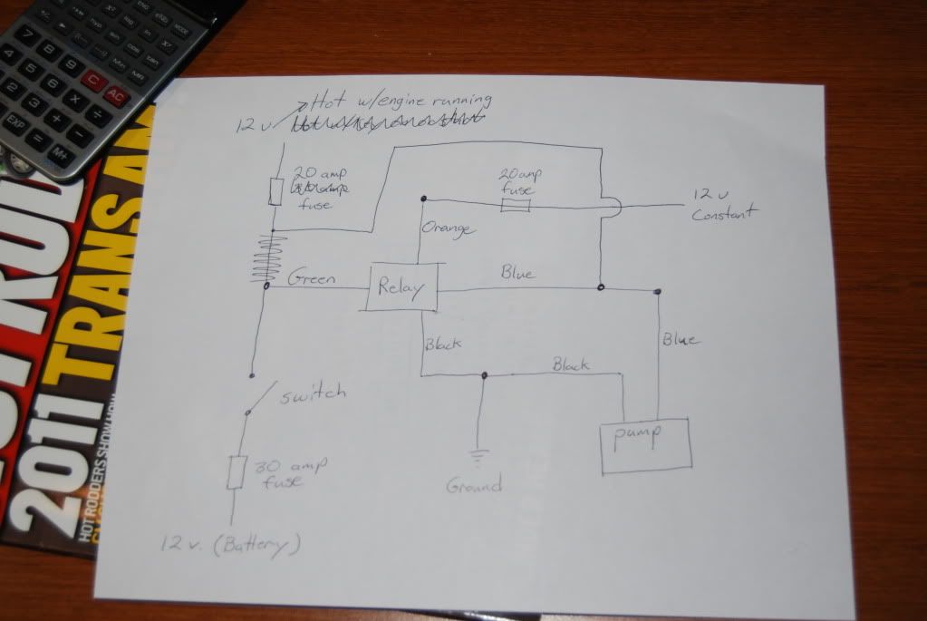
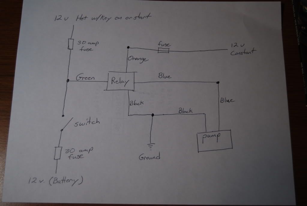
The only thing I can think of is the relay is drawing a bunch of amperage and the only reason why the the switch seems to work is the long length of wire running back and forth to the cabin is eating up some of the amperage and the fuse is staying intact. This seems kind of far fetched but I can't think of any other reason why I can't get this to work as it's supposed to. Below is a schematic of how I have everything wired up. Can anyone see why this wouldn't work properly. I would think that my added switch wouldn't work before the regular wiring wouldn't. I'm baffled.

DSC_1154-2.jpg
 

07 Boss

Senior Member
Joined
Jan 25, 2009
Posts
3,858
Reaction score
989
Location
Sin City
To test my theory of the wire length I ran the green signal wire through about 30 feet of 16 guage wire and and the pump ran for about 20 seconds, then the fuse blew. So it is my conclusion that the relay signal wire is drawing too many amps. Is this possible? How many amps should the relay, not the actual pump, be drawing? Can I put some kind of resistor wire in there to decrease the amperage? Or should I look into getting another relay from Meziere?
 

tapsport

Junior Member
Joined
Mar 25, 2009
Posts
24
Reaction score
0
relays themselves draw very little amps, 5 amp fuse would be more than enough, it is only powering a tiny coil to draw in a contact, it looks like the orange and green wires are backwards, you need the constant power wire going to battery with 30 amp fuse, and signal wire going to all your switches , let me know how that works
 

tmcolegr

It's All About the Build
Joined
Aug 14, 2007
Posts
3,263
Reaction score
18
Location
Central, FL
Here's Meziere's Instructions. I just checked mine and the signal wire which activates the relay draws less than 1 amp so it should not be blowing a 30 amp fuse.

Hint:
  • Make sure the relay is mounted when your finished - they don't like vibration and will fail
  • Carry a spare relay in the glove box - they do fail at the most inopportune times (midnight out in the middle of nowhere on a Sunday)
 

Attachments

  • Meziere WIK346 Relay.pdf
    34 KB · Views: 38
Last edited:

07 Boss

Senior Member
Joined
Jan 25, 2009
Posts
3,858
Reaction score
989
Location
Sin City
relays themselves draw very little amps, 5 amp fuse would be more than enough, it is only powering a tiny coil to draw in a contact, it looks like the orange and green wires are backwards, you need the constant power wire going to battery with 30 amp fuse, and signal wire going to all your switches , let me know how that works

The orange, or red, wire with the 20 amp fuse that came with the wiring does go to the battery. Or at least the battery connection to the fuse box. And the green signal wire does go to my switches, one fused toggle switch and one fused key on power source. I know the relay wiring is correct because the fan works when I flip the switch in the cabin. I've been driving around with it for 3 days now. I just can't get it to turn on automatically when the ignition key turns to on. It is at that point the fuse blows.

The only difference between completing the 2 circuits is that one has much more wiring and goes through a splice. I will redo the splice this evening but I doubt that's going to help. I don't understand how the green signal wire can draw juice one way and not the other. I know the circuit works because when I attach the green signal wire directly to the keyed power source, the pump goes on. But it is drawing too much juice and blows the fuse when I put a fuse in line.
 

07 Boss

Senior Member
Joined
Jan 25, 2009
Posts
3,858
Reaction score
989
Location
Sin City
Here's Meziere's Instructions. I just checked mine and the signal wire which activates the relay draws less than 1 amp so it should not be blowing a 30 amp fuse.


Hint:
  • Make sure the relay is mounted when your finished - they don't like vibration and will fail
  • Carry a spare relay in the glove box - they do fail at the most inopportune times (midnight out in the middle of nowhere on a Sunday)


Here is where I mounted the relay, toward the front of the fuse box. When a relay goes out, can it draw enough amps to blow a fuse, or does it just not work? Is blowing the fuse a symptom of a bad relay?

DSC_1147-1.jpg
 

tmcolegr

It's All About the Build
Joined
Aug 14, 2007
Posts
3,263
Reaction score
18
Location
Central, FL
When a relay goes out, can it draw enough amps to blow a fuse, or does it just not work? Is blowing the fuse a symptom of a bad relay?

A relay can fail in several ways:
  • A relay can fail due to being open - which means it no longer functions. This does not cause a fuse to blow.
  • A relay can fail if it is shorted closed - this will cause it not to turn the accessory off (water pump in your case) when the voltage from the signal wire is removed. This does not cause a fuse to blow.
  • A relay can also fail if it is shorted to ground - this does blow a fuse.
Another reason a fuse can blow is if the circuit is drawing more amps than the fuse is rated for. This can be for many reasons:
  • Circuit is overloaded or too low of an amp rating for the circuit
  • loose connection
  • moisture in a connection
  • etc.
 

MikeVistaBlue06

Inventor: Asshole Points
S197 Team Member
Joined
Apr 5, 2007
Posts
2,169
Reaction score
31
Location
Richardson TX
Make sure you have the load across the correct two terminals of the relay.

It should be marked on the bottom of the relay--someone may have messed up putting the colored wires on it.

You can also use an ommeter to check out which should be the two for the relay and which two are for the load.

With a coil in there to activate the relay, you will see some resistance. The other two should be OPEN when not activated (assuming you have a normally open relay).

HTH

Mike
 

07 Boss

Senior Member
Joined
Jan 25, 2009
Posts
3,858
Reaction score
989
Location
Sin City
in your diagram, which fuse is blowing?

The one in the upper left on the signal wire going to a 12v key on power source. Like I was saying, it runs fine when I flip the cabin switch on the lower left of the diagram. In theory the cabin switch circuit should be drawing the same amperage as the key on power source circuit; they are conected to the same wire going to the same relay.

Tonight, after the little one goes to sleep, I'm going to cut the relay out of the equation for the 12v key on power source. After all the relay kit is an optional item for running the pump on the engine. If it works fine then I will know for sure it is an issue with the relay. And that the only reason why the cabin switch circuit works is the length of wire must have enough resistance or something to keep the draw through the fuse at acceptable levels. On that note I'm going to progressively lower the amperage on the fuse on that circuit and see at what point it blows. This too will tell me there's something wrong with the relay if this thing is supposed to draw less than 1 amp.
 
Last edited:

07 Boss

Senior Member
Joined
Jan 25, 2009
Posts
3,858
Reaction score
989
Location
Sin City
Make sure you have the load across the correct two terminals of the relay.

It should be marked on the bottom of the relay--someone may have messed up putting the colored wires on it.

You can also use an ommeter to check out which should be the two for the relay and which two are for the load.

With a coil in there to activate the relay, you will see some resistance. The other two should be OPEN when not activated (assuming you have a normally open relay).

HTH

Mike


Well the relay has to be hooked up right because the cabin switch hooked to the signal wire runs the pump just fine and I haven't had any issues with that for 4 days now. I'm gonna try the steps mentioned above tonight and if everything works as I predict, the issue would have to be that relay is just drawing too many amps.
 

07 Boss

Senior Member
Joined
Jan 25, 2009
Posts
3,858
Reaction score
989
Location
Sin City
Thanks guys for the helpful input. I just ended up bypassing the relay with the key on power source. I actually used the cruise control circuit which is not a key on power source but an only hot with the engine running power source. So the pump only runs when the engine is running like the oem one. Also this way you don't have to worry about pulling the fuse when your tuner is plugged in. You know how they don't like motors and stuff running when they are trying to communicate. I kept the cabin switch running throught the relay though. So I changed up the schematic with the new bypass. I never did figure out why the original diagram kept blowing that fuse. There isn't any reason why it shouldn't have worked.

DSC_1155-1.jpg
 

MikeVistaBlue06

Inventor: Asshole Points
S197 Team Member
Joined
Apr 5, 2007
Posts
2,169
Reaction score
31
Location
Richardson TX
Well the relay has to be hooked up right because the cabin switch hooked to the signal wire runs the pump just fine ......

What if it is wired such that Green is feeding your load rather than orange, and the switched 12V at the bottom can supply enough power w/o blowing the fuse.

I'd still check to see how those wires are put across that relay, but that's just the EE in me talking...

Mike
 

dustindu4

Member
S197 Team Member
Joined
Aug 4, 2007
Posts
330
Reaction score
1
do yourself a favor and make sure the relay is screwed down so it can't bounce around. ENGINE TEMPERATURE WARNING messages on your message center aren't very fun. Especially when crossing the finish line going 110 and spraying coolant all the way down the track, people will get mad at you.
 

07 Boss

Senior Member
Joined
Jan 25, 2009
Posts
3,858
Reaction score
989
Location
Sin City
What if it is wired such that Green is feeding your load rather than orange, and the switched 12V at the bottom can supply enough power w/o blowing the fuse.

I'd still check to see how those wires are put across that relay, but that's just the EE in me talking...

Mike

Oh I see what you are saying. Yes if they were backwards the pump would still work with the switch. Still wouldn't explain why the 30 amp fuse was blowing though. The motor has a 20 amp fuse on the power wire so I don't think that would be the reason. Also when I flip the switch I can hear the relay click over. But I will double check it tonight. I did drive to work this morning without any issues though. So now I just have to go back and clean up the harness, again.
 

07 Boss

Senior Member
Joined
Jan 25, 2009
Posts
3,858
Reaction score
989
Location
Sin City
do yourself a favor and make sure the relay is screwed down so it can't bounce around. ENGINE TEMPERATURE WARNING messages on your message center aren't very fun. Especially when crossing the finish line going 110 and spraying coolant all the way down the track, people will get mad at you.

Thanks, but it is locked down tight.

DSC_1147-1.jpg
 

Skarkull

forum member
Joined
Jun 27, 2009
Posts
357
Reaction score
4
DSC_1154-2.jpg


I edited your photo, your missing two diodes, they keep the voltage from going backwards.
 

TexasBlownV8

Formerly TexasBlownV6
Joined
Apr 4, 2008
Posts
4,973
Reaction score
54
Location
Central Texas
The other option is to put the switch where you have "Green", so the common end of the switch goes to the relay, the other two to either key-on power or to battery voltage. that's how I have mine wired, and no diodes needed.
You need a SPDT switch for this.

And, for the fused circuit going into the relay, you should make that 5A. The coil-side of the relay won't take that much to trigger.

What's the numbers on the pins of the relay where each wire goes? One of them could be wrong. Green and black should be 85 and 86; pins 30 and 87a on the orange and blue wires.
 
Last edited:

Skarkull

forum member
Joined
Jun 27, 2009
Posts
357
Reaction score
4
cache.php


That is the image provided by Meziere. However, I did find this on LS1howto.com

_relay_diagram.jpg


That diagram corresponds with how you say the wires should be wired in. Now just add the diodes and switch for manual operation

_relay_diagram_w_switch.jpg


I don't think it matters which way power is applied across 85 and 86 so long as power is there.
 

Support us!

Support Us - Become A Supporting Member Today!

Click Here For Details

Sponsor Links

Banner image
Back
Top