SC_Stang
Junior Member
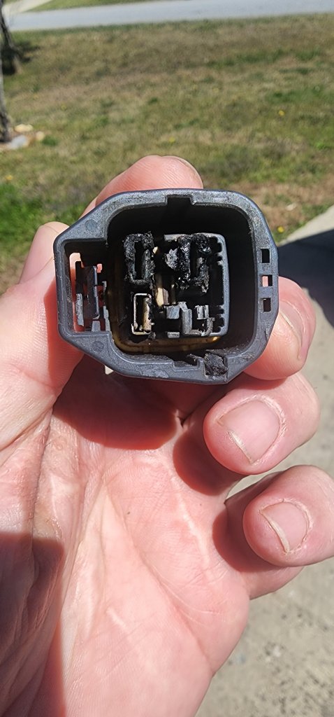
Had an overheating issue on my 2014 GT and through troubleshooting and research found that I was a victim of the dreaded “cooling fan drawing too much power and melting the connectors issue”.
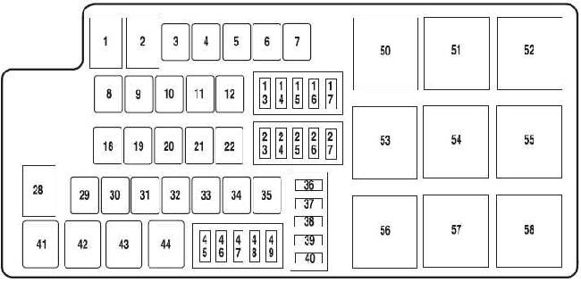
For troubleshooting - If you turn your AC on, your fan should start. If it does not come on, run a jumper wire from the battery – neg to black, pos. to either green w/white stripe (low side) or white (high side) on the resistor plug to test fan functionality. If your fan spins, there is an issue with the wiring along the way. While you are in there, check the plug for melted plastic – this is one of the trouble areas. The other is in the BEC (Bussed Electrical Center) – where all your fuses and relays reside on the passenger side of the engine compartment. You likely will not be able to see melted plastic in the BEC unless you pull it apart and look inside but you may be able to see melted plastic on the pins of the OEM relays in the BEC. The high-speed relay is in slot 50 and the low-speed relay is in slot 55. This process will bypass the BEC for both fan circuits, so it is not necessary to pull the BEC apart and check for damage unless you just want to. In the end, I pulled both relays from the BEC as they were no longer needed, and they will be good for spares in the future (technically you could use them for this how-to as long as they are still good).
I could not find a straight-forward how-to on fixing the issue so after running and tracing wires for the better part of a Saturday (mostly user error due to obtaining an incorrect wiring diagram), I figured I would post to see if I could help some folks out. From what I understand on the wiring diagram, this procedure should cover 2010-2014 Mustangs.
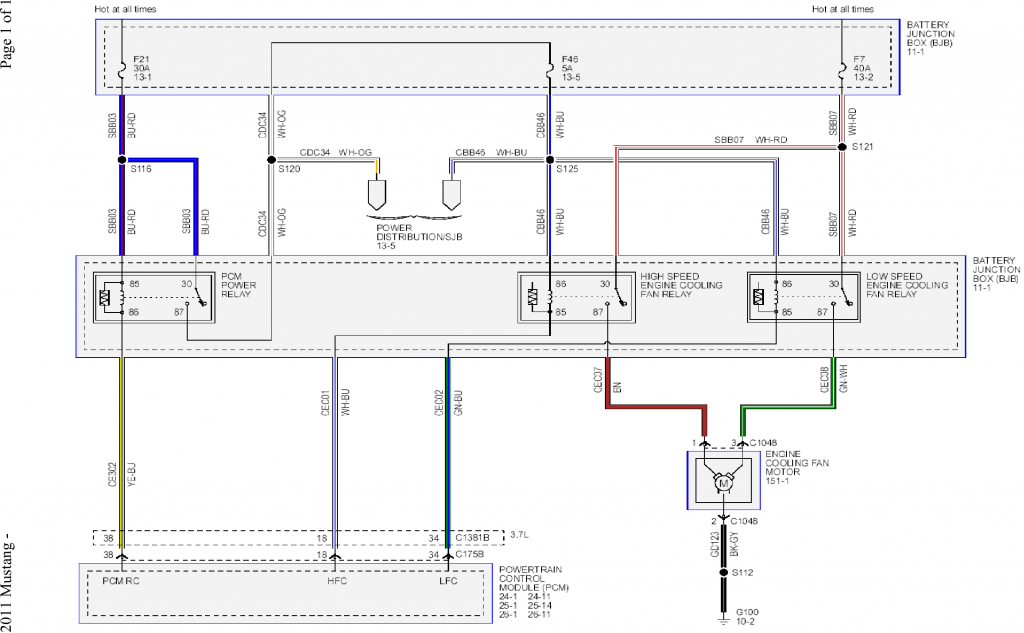
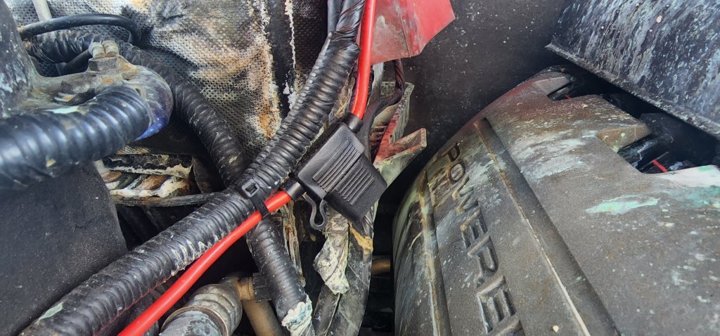
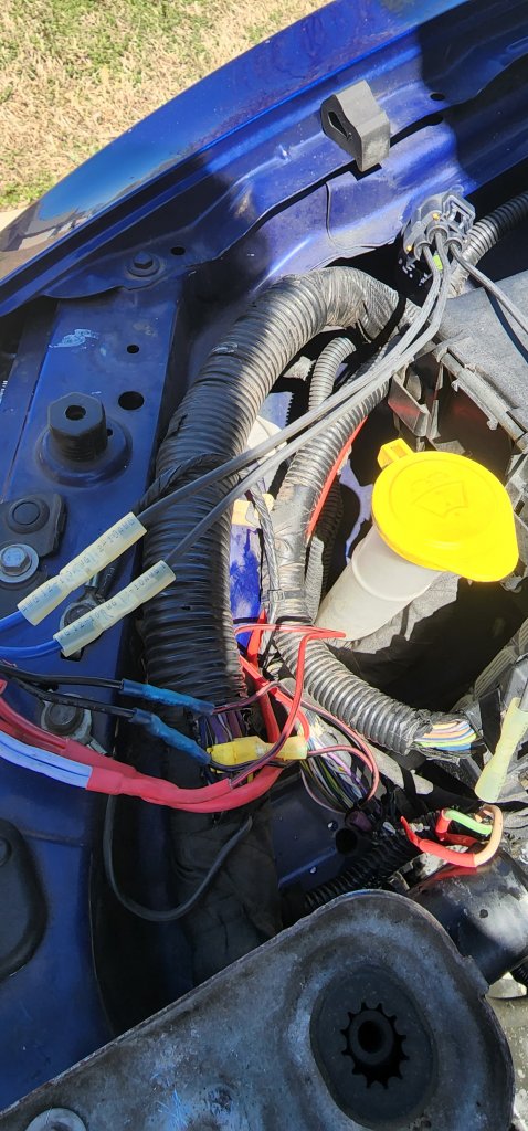
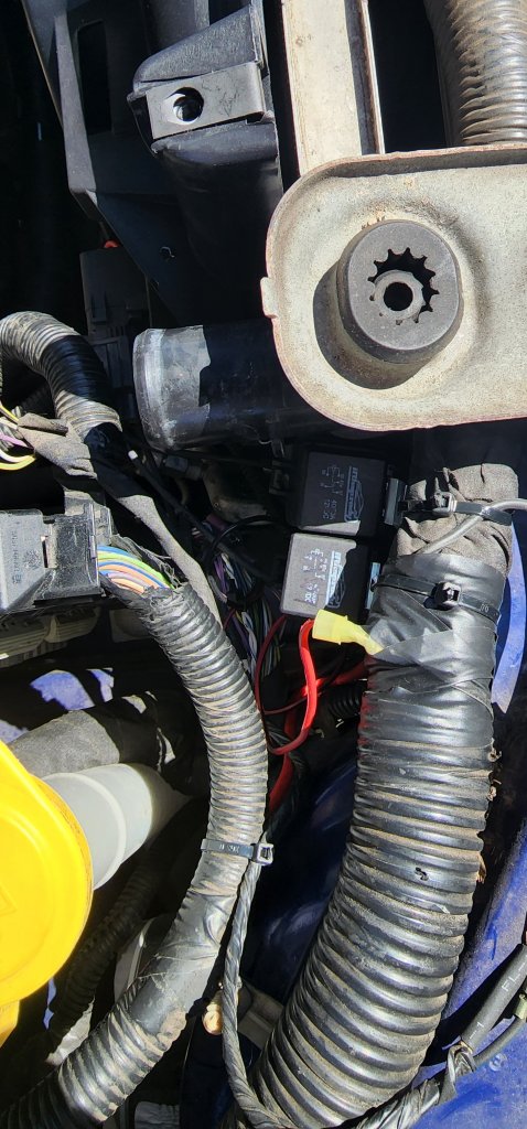
I ran a 40a fused 10ga primary power wire from the battery to the front fan area of the car (underneath the radiator cover just in front of the PCM) – this is where I tied up the relays when finished. This went to pin 30 (red wire if you bought the relays with color-coded connectors) on both relays. Excuse my mess... had to clean some terminal corrosion off of my battery.
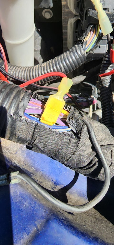
I tapped into a Violet w/ Green stripe wire in the large loom at the front of the car for switched power. I used a tap but honestly, I hate them. If I was going to redo it, I would just cut the wire and use a butt connector with heat shrink. This wire will connect to pin 86 (white wire) on both relays.
Next, I ran 10ga wire from pin 87 (blue wire) on each of the relays to the new resistor plug (mine was melted beyond repair - see first image above). The high-speed relay blue wire will go to the white wire on the connector. The low-speed relay blue wire will go to the green w/white stripe wire on the connector.
The trigger wires for the relays will come from the bottom connector of the PCM. I used a meter to check continuity from pin 85 on the OEM high-speed (50) and low-speed (55) relay connectors in the BEC. The low-speed trigger on the PCM connecter is a green w/blue stripe wire and the high-speed trigger is a white w/blue stripe wire. You can cut these and connect the PCM side to pin 85 (black wire) on each of the relays. I would heat shrink the ends of the leftover wires just as a formality, these are ground triggers so you technically will not have to worry about them shorting out – just good form . Clean up wiring and test functionality.
Links to the stuff I used for reference:
Primary Wire
Relays
Inline Fuse Holder
Engine Cooling Fan Motor Connector
Hope this helps some folks out. I assume this procedure is the same on a 2010-2014 V6 as well.
For troubleshooting - If you turn your AC on, your fan should start. If it does not come on, run a jumper wire from the battery – neg to black, pos. to either green w/white stripe (low side) or white (high side) on the resistor plug to test fan functionality. If your fan spins, there is an issue with the wiring along the way. While you are in there, check the plug for melted plastic – this is one of the trouble areas. The other is in the BEC (Bussed Electrical Center) – where all your fuses and relays reside on the passenger side of the engine compartment. You likely will not be able to see melted plastic in the BEC unless you pull it apart and look inside but you may be able to see melted plastic on the pins of the OEM relays in the BEC. The high-speed relay is in slot 50 and the low-speed relay is in slot 55. This process will bypass the BEC for both fan circuits, so it is not necessary to pull the BEC apart and check for damage unless you just want to. In the end, I pulled both relays from the BEC as they were no longer needed, and they will be good for spares in the future (technically you could use them for this how-to as long as they are still good).
I could not find a straight-forward how-to on fixing the issue so after running and tracing wires for the better part of a Saturday (mostly user error due to obtaining an incorrect wiring diagram), I figured I would post to see if I could help some folks out. From what I understand on the wiring diagram, this procedure should cover 2010-2014 Mustangs.
I ran a 40a fused 10ga primary power wire from the battery to the front fan area of the car (underneath the radiator cover just in front of the PCM) – this is where I tied up the relays when finished. This went to pin 30 (red wire if you bought the relays with color-coded connectors) on both relays. Excuse my mess... had to clean some terminal corrosion off of my battery.
I tapped into a Violet w/ Green stripe wire in the large loom at the front of the car for switched power. I used a tap but honestly, I hate them. If I was going to redo it, I would just cut the wire and use a butt connector with heat shrink. This wire will connect to pin 86 (white wire) on both relays.
Next, I ran 10ga wire from pin 87 (blue wire) on each of the relays to the new resistor plug (mine was melted beyond repair - see first image above). The high-speed relay blue wire will go to the white wire on the connector. The low-speed relay blue wire will go to the green w/white stripe wire on the connector.
The trigger wires for the relays will come from the bottom connector of the PCM. I used a meter to check continuity from pin 85 on the OEM high-speed (50) and low-speed (55) relay connectors in the BEC. The low-speed trigger on the PCM connecter is a green w/blue stripe wire and the high-speed trigger is a white w/blue stripe wire. You can cut these and connect the PCM side to pin 85 (black wire) on each of the relays. I would heat shrink the ends of the leftover wires just as a formality, these are ground triggers so you technically will not have to worry about them shorting out – just good form . Clean up wiring and test functionality.
Links to the stuff I used for reference:
Primary Wire
Relays
Inline Fuse Holder
Engine Cooling Fan Motor Connector
Hope this helps some folks out. I assume this procedure is the same on a 2010-2014 V6 as well.
Last edited: