Planning a Ford Racing “Aluminator” Build with associated mods over the winter

Scott

Senior Member
S197 Team Member
Joined
Nov 17, 2009
Posts
2,337
Reaction score
43
Location
King City, Ontario, Canada
Very nice write up and execution. Been thinking about this for a while but other necessary car expenses keep getting in the way. Maybe one day

Thanks Andrew, fit and finish on the kit is excellent, but then again there is the cost!

I like that a lot!!! Nice work..

Kurt thanks. I am making a little progress on my stock pile of parts. Have not forgotten about the Power Pipe!

looks great Scott!

Thanks Paul!
 

Scott

Senior Member
S197 Team Member
Joined
Nov 17, 2009
Posts
2,337
Reaction score
43
Location
King City, Ontario, Canada
BMR Bushing Install

My new differential housing did not come with a bushing installed.

OEM differential bushing part number BR3Z-5A638-B


As previously posted the rubber and steel sleeve were removed from the OEM bushing with a drill and whole saws then cleaned up with a wire wheel.


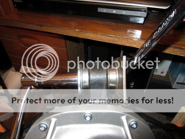
To install the OEM bushing case into the housing I assembled a tool from ½” bolt, a few large flat washers, a ½” ID bearing, a piece of 3/16 steel plate and an old carrier bearing.


The housing and shell were lubricated with WD40. The bushing shell was pulled through according to the Ford specifications until there was 12 mm (0.47”) between the shell and the differential housing.


The passenger side of the OEM shell necks down a bit and it looks as if it is going to be challenging to get the BMR bushing inserted. That's a job for tomorrow.


Scott

Senior Member
S197 Team Member
Joined
Nov 17, 2009
Posts
2,337
Reaction score
43
Location
King City, Ontario, Canada
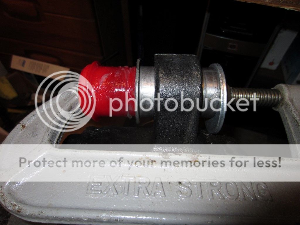
Installed the BMR Suspensions Differential Bushing Kit part number EN001 with a 6” C-Clamp, Rubber Mallet, Large Steel Washer, a Carrier Bearing cone and a liberal coating of BMR Superlube, part number SUL41150.

Started out this way and when the bushing got near to the passenger side I added the carrier bearing cone for additional travel:


Done:


Scott

Senior Member
S197 Team Member
Joined
Nov 17, 2009
Posts
2,337
Reaction score
43
Location
King City, Ontario, Canada
Differential Finally Assembly, Well Almost!

Moved the differential from the laundry room back into the garage last weekend in preparation for final assembly.


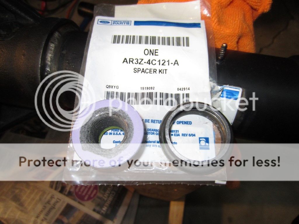
Things were going very well until I ran into a little problem with the pinion bearing pre load (the amount of torque it takes to move the pinion gear). I set my target at 22 in-lbs right in the middle of what Ford recommends (16 – 28 in-lbs). Well in my trial install I ended up with 32 in-lbs and this time I was in the order of 50 in-lbs. It seems I just do not have the magic touch or intuition to know exactly when you are going from too loose to too tight when torqueing down on the pinion nut. Luckily I have one more AR3Z-4C121-A Purple Pinion Nut and Sleeve. If I screw this one up it is back to the dealership for me.

Progress so far. Removed the girdle.


Removed the nuts, studs and carrier caps.


Pulled the spool, ring gear bearing cups, and carrier shims out. Bagged the LH and RH shims for reassembly.


Removed the pinion nut with a 1-1/16” socket and my pinion flange tool. Removed the pinion flange with a 6” two jaw puller and a ¾” socket.


Removed the “trial slip-on” inner pinion bearing and the pinion shims.


I ended up with 2 shims to get the tooth pattern I was after. The shims measured 0.010” and 0.022” for a total of 0.032”.


Setup my 12 ton press to install a new inner pinion bearing.


And pressed the bearing on.


Added new crush sleeve.


Slipped the pinion into the housing, applied a little ARP Assembly Lubricant to the underside of the nut.


And a little Anti-Seize to the pinion flange splines.


Next the pinion nut was tightened using my pinion flange tool, a 1-1/16” socket and breaker bar with a pipe extension. Once the “wobble” was taken out I removed the pinion flange tool and checked the bearing preload. This was done after every pull on the breaker bar. But unfortunately as mentioned earlier I went from too loose to too tight in the last pull.

More to follow…..
 

Scott

Senior Member
S197 Team Member
Joined
Nov 17, 2009
Posts
2,337
Reaction score
43
Location
King City, Ontario, Canada
Back to it today with a new pinion nut and sleeve, drum roll please .... with the help of my youngest daughter's boyfriend we managed to get the pinion preload set to 22-24 in-lbs range.


Installed the Moser carrier studs and tightened to 10 ft-lbs, in my case after the ft-lbs to Nm conversion I tightened them to 13.6 Nm with a 3/16” Allen socket.


Put the LH carrier shims used in my trial assembly in place.


Applied gear lube to the carrier bearings, slipped the carrier in without too much damage to my fingers and applied a little gentle pressure to ensure the LH bearing was fully seated.


Slipped the RH shims in place used from the trail assembly and used small rubber mallet to carefully seat the last tick shim.


Installed the carrier bearing caps and applied a little ARP Assembly Lubricant to the underside of both the Moser washers and nuts.


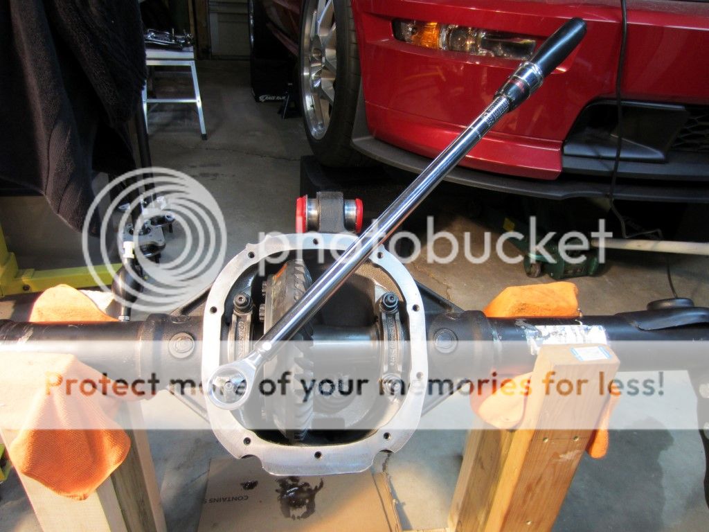
Tighten the Moser nuts to 90 ft-lbs with a 3/4” deep socket.


Checked the backlash in a couple of spots and it looks good at 0.009”


Applied some marking compound.


Drive pattern.


Coast pattern.


Scott

Senior Member
S197 Team Member
Joined
Nov 17, 2009
Posts
2,337
Reaction score
43
Location
King City, Ontario, Canada
Lube Locker gasket slipped on.


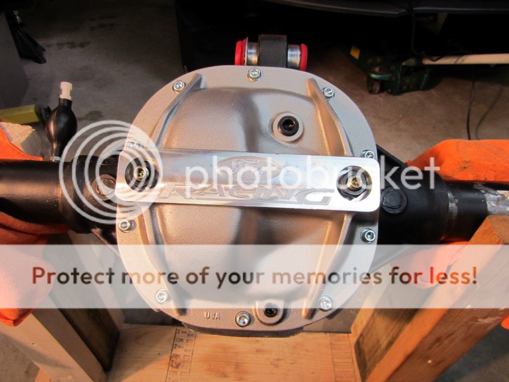
FRPP Girdle temporarily installed to be replaced with an OEM cover to paint the housing.


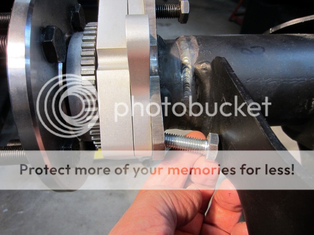
With the axle tubes shortened one inch per side the safety hub bolts provide in the C-Clip Eliminator kit were too long to fit in between the shock mount and axle end. A 10.9 bolt was cut about ¼” shorter than the bolts provide from Strange.


Axle housing all ready for paint.


Axle housing cleaned up and painted with a satin black roll bar & chassis paint. Clearly not powder coat but it gets the job done.


05stroker

Never enough power guy!
Joined
Mar 2, 2008
Posts
13,058
Reaction score
77
Location
Bullard Tx.
I like the shit out of this gasket! I need to keep that in mind for the next time the cover is off.
 

Scott

Senior Member
S197 Team Member
Joined
Nov 17, 2009
Posts
2,337
Reaction score
43
Location
King City, Ontario, Canada

Scott

Senior Member
S197 Team Member
Joined
Nov 17, 2009
Posts
2,337
Reaction score
43
Location
King City, Ontario, Canada
Backed out the load bolts on the girdle sufficiently so they would not contact the differential bearing caps while installing the girdle. Installed the girdle with a Lube Locker gasket and tightened the bolts with a ¼” hex socket to 20 ft-lbs in a crisscross pattern from the center out.

The two load bolts were turned down until they maybe contact and then torqued to 5 – 10 ft-lbs, in my case 11.8 Nm. The two load bolt jam nuts were tightened to 25 ft-lbs with a 7/8” socket and a drop of blue Loctite on the threads.


Applied Loctite 567 Thread Sealant to the girdle drain set screw and snugged it down with a ¼” Allen socket and 3/8” ratchet.


Will apply thread sealant to the filler set screw on the girdle and housing when gear oil is added to the differential.

Cleaned the housing ends and applied a liberal bead of Permatex Gear Oil RTV Gasket, part number 31872 around the axle tube ends. The RTV will be sandwiched between the inboard side of the Strange Engineering caliper mount and the housing end face.


Grease was applied to the axle splines and the axles where slipped in (short axle on driver’s side), caliper brackets were aligned facing the front of the car. Bolts were installed finger tight and let sit for an hour consistent with the RTV instructions. Then safety hub bolts that could be accessed were tightened to 35 ft-lbs with a 16mm socket the two that could be only accessed with a wrench were “snugged” down to hopefully close to 35 ft-lbs.


ABS sensor and retaining bolt will be installed when the axle is installed in the car.

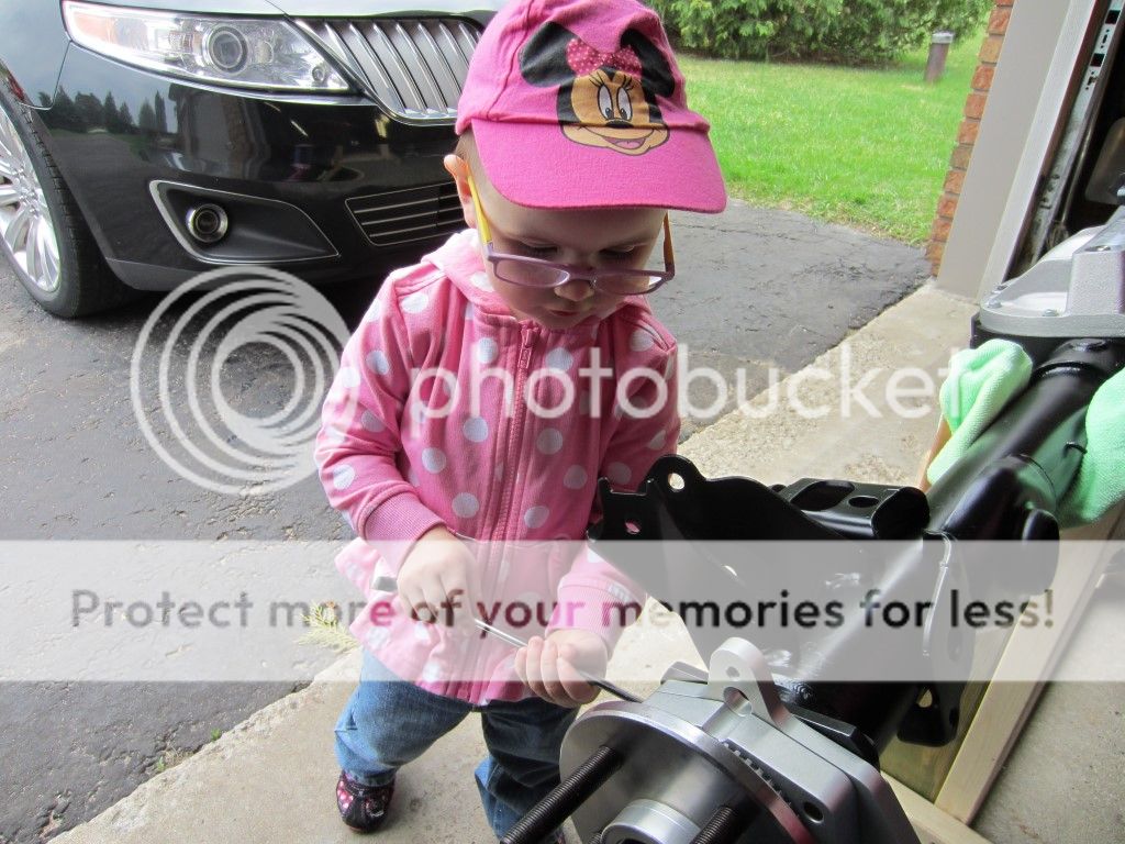
As most I you know I make pretty slow progress, but today was exceptionally slow as my apprentice who will be two years old in three days wanted to double check everything I did!


Scott

Senior Member
S197 Team Member
Joined
Nov 17, 2009
Posts
2,337
Reaction score
43
Location
King City, Ontario, Canada
^^ As always that is some super clean, beautiful work! And a GREAT apprentice too!

Thanks Kyle! I hope my granddaughter turns out better as an apprentice then my three girls. When they were too young to know how they wanted to help and once they were old enough to know how they no longer wanted to help!
 

Scott

Senior Member
S197 Team Member
Joined
Nov 17, 2009
Posts
2,337
Reaction score
43
Location
King City, Ontario, Canada
BMR Sway Bar Relocation kit installed, part number SRK00. Bottom of the
OEM mount was previously cut off.


Passenger side installed.


Driver side installed.


BMR Lower Control Arm Relocation Brackets installed, part number CAB005.

Passenger side was installed using a 22mm wrench, 22mm socket and a 19mm socket. The sleeve cross bolt and the upper arm bolt will be tightened to 129 ft-lbs when the differential is installed. The 14mm bolt where the damper weight would be will be tightened to 45 ft-lbs with a 19mm socket.


Driver’s side, fasteners will be tightened similar to the passenger side.


Scott

Senior Member
S197 Team Member
Joined
Nov 17, 2009
Posts
2,337
Reaction score
43
Location
King City, Ontario, Canada
BMR Subframe Connector Install

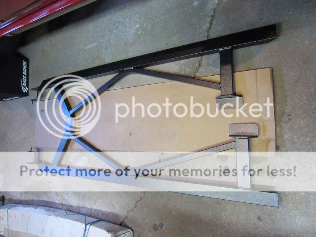
BMR Subframe Connectors, part number SFC011 out of the box.


Passenger side of the car illustrated on all pictures unless otherwise noted.

With the car on 12” Race Ramp Wheels Cribs a 10mm deep socket was used to remove both parking brake cable brackets.


With a 13mm deep socket both heat deflectors were removed.


Using a 10mm deep socket the two bolts and two nuts were removed, a panel tool was used to release the three plastic retainers and then the driver’s side plastic fuel line cover was removed.


The passenger side subframe connector was lifted and held in place with a pair of floor jacks.


Using a marker all of the weld points were traced like this using the subframe connector as a template.


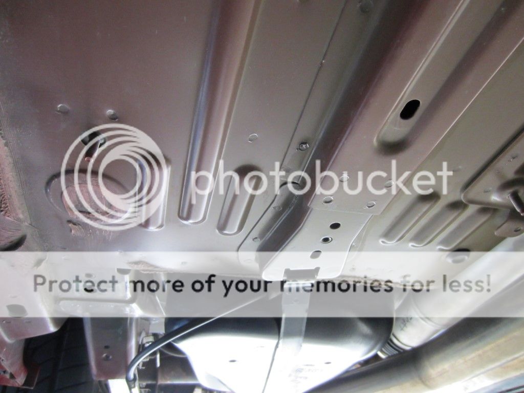
The passenger side subframe connector was lowered and the paint was ground off the weld contact points on the chassis.


And on the connector.


Stay tuned....
 

Latest posts

Support us!

Support Us - Become A Supporting Member Today!

Click Here For Details

Sponsor Links

Banner image
Back
Top