What IS a Splitter?
“A splitter is a horizontal shelf mounted under the nose of the car, or to the bottom of an air dam, with the top side of the splitter sealed to the body. A splitter produces downforce from the difference in air pressure on the top and bottom surfaces of the splitter area. Because airflow over the top is blocked by the body or air dam, the local airspeed is low and the air pressure on top is high. Because air can flow under the splitter freely, the local airspeed under it is high and the air pressure on the bottom side is low. More splitter area produces more front downforce, but only up to a point. The effectiveness of adding splitter area falls rapidly as it extends away from the body. That is because the difference in airspeed between the top and bottom sides decreases with distance away from the body. The useful length is 4 to 5 inches.” (Neil Roberts, NASA Speed News May 2013, pg. 36)

Splitters seem to be all the rage since the release of the Boss 302. The Laguna Seca Boss has popularized this very effective aero device and brought it from the fringe realm of racing and into the minds of the street warriors. I even had someone refer to my adaptation of the splitter on my car as a “Laguna Seca Splitter,” to which I promptly corrected that it was just a splitter; no Laguna Seca about it.
Despite what little vanity that comes from having the latest fad hanging from the nose of my car, my primary motivation in making a splitter was to use it at the track to make front end downforce. On the legacy S197, there are little to no options for an off the shelf solution that are not built with cosmetics as the primary focus. This leaves us with fabricating one as the only option. My car has a CDC Classic chin spoiler installed to act as an air dam. It looks aggressive enough and serves the purpose of effectively lowering the front bumper closer to the ground. It has a couple of flaws inherent in the design of it however. Firstly, it is entirely too flexible and bows under load. Being attached with only 3M tape, it quickly begins to lift off of the leading edge of the bumper where it attaches. I have since riveted the whole assembly to the bumper. Secondly, it is completely hollow behind the leading edge. This is just another of the many places on the underside of our cars for there to be drag.

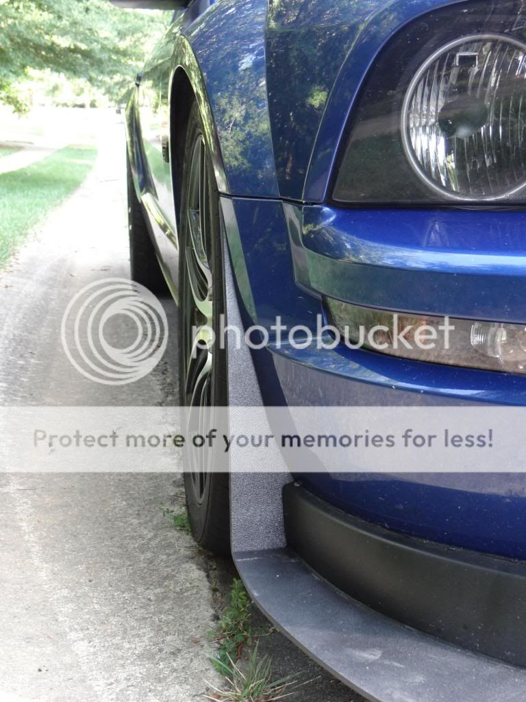
Here you can see how it comes to a point in the middle. Upon closer inspection you would find that it was not even attached on the top where the tape used to hold it.

Supporting mods
Nevertheless, it serves as a good flat place to butt the splitter against. However, it requires some extra reinforcement to serve as a good platform for attaching it. I debated making a second sheet metal undertray that stretched from end to end as well as a simple sheet metal lip that would reinforce the inside edges of the chin spoiler. What I ended up with was a local reinforcement plate in the location of my planned attachment points as well as two gusset plates that sandwiched between the chin spoiler and the actual bumper itself.

The Gusset Plate. This was first riveted to the chin spoiler, and then riveted to the bumper through all 3.
In addition to these reinforcements I added two pieces of extruded aluminum angle that were notched to slide flush against the inside of the chin spoiler. These extend all the way to the rear and then tie into another piece of angle that is mounted perpendicular and riveted to the gusset plates on either side.
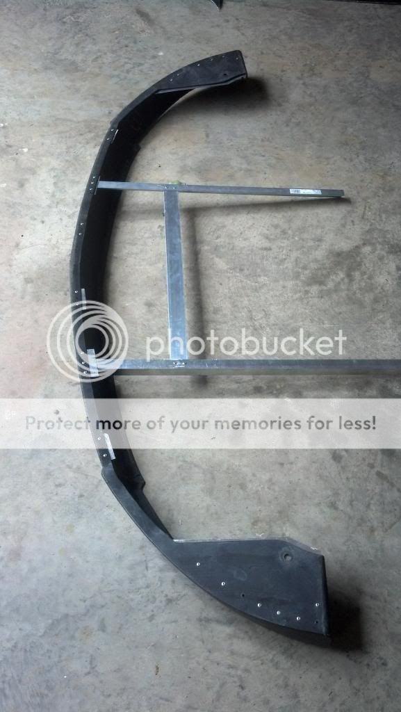
The reinforced attachment points and extruded aluminum angle

The perpendicular angle tied together with the other two.

Where the perpendicular support, bumper, gusset plate, and chin spoiler all tie together.
This structure serves to make the entire bumper assembly more rigid and to provide some attachment points that weren’t soft plastic. The intention was to put rivnuts in my reinforced areas, but I made the mistake of riveting the plates to the chin before installing the rivnuts. This left the bottom side as the only place to work and the soft plastic didn’t take to having a rivnut expanding in it. This left me with the tried and true bolt/washer/nut combo which is much more of a pain in the ass, but effective nonetheless. With the support structure completed, I still needed to have a solid attachment point for the support rods. I bought off-the-shelf longacre turnbuckle rods and backing washers to serve as the vertical supports, but I could not install them into something like the Laguna Seca bracket because it installed in the same place as my heat exchanger. The heat exchanger situation changed, but I still proceeded with my original plan to weld some U brackets to the front bumper beam. This is a simple and effective solution for those of you looking to accomplish a splitter on your GT500.


Fabricating the Splitter
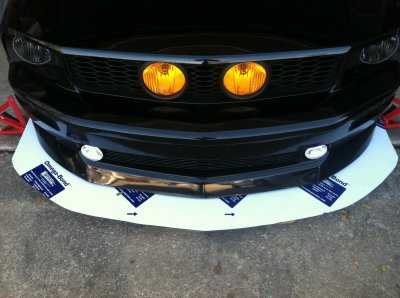
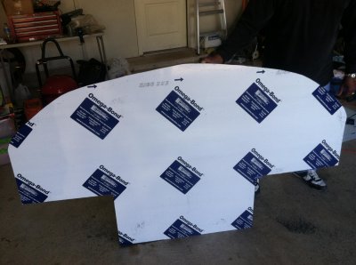
The splitter itself was first prototyped with some cardboard. I wanted to maximize the downforce available from this project and so opted to get as close to the 5 inch maximum before getting into diminishing returns territory. Also, the splitter needs to be AT LEAST as long as your cars height off of the ground. In addition, I wanted the splitter to extend out to the edge of the tire when the wheels are pointing straight. Once I got the general shape I wanted, it was time to cut. I used a 3” pneumatic cutting disc and it was probably the worst tool for this job. It spun too fast and melted the plastic instead of cutting it. This required a lot of work with a plane and a file to get a smooth edge later on.


The material is ¼” Black ABS plastic that I got from a local plastic and composites supply company. I chose this material for a couple of reasons. I wanted something simple to work with that didn’t require a lot of set up, sanding, painting, etc. like fiberglass would have since I am (A) inexperienced in laying up fiberglass and (B) kinda lazy. Also, ABS plastic was cheap at $100 for a 4’ by 8’ sheet , and would be easily replaced in the event that an off track excursion required the fabrication of a new one. Plus, I figured that if the LS/302S splitter and the FR500S splitter were made out of it, it was good enough for me. I will discuss my findings at the conclusion of this writeup.
Finally, once the supporting modifications were completed and the splitter cut and trimmed, it was time to mount it. The splitter gets mounted to the bumper with it off the car, leaving the support rods as the only part that needs tightening once the bumper is in place. It is important to note the importance of putting lock-tight on each and every nut and bolt in the assembly. I failed to do so on the rods and installed them as they came in the package. I ended up losing a screw that held the turnbuckle to the splitter and had to find a replacement at the hardware store.

The finished product
Fender Extensions
The pressure drag that comes from rotating tires in the airstream is quite large. In an attempt to decelerate the airflow in a controlled fashion in front of the tires I wanted to create a vertical wall, a gurney flap on the fender wells that tied into the splitter. This should reduce drag as well as add a bit of downforce. I made these out the same ABS plastic and then molded them to the shape of the fender well with a heat gun. A piece of aluminum angle ensures that the flap stays butted up against the trailing edge of the splitter. The angle is attached to the splitter using rivets but the flap just rests in it. The flap is attached to the bumper using factory holes in the bumper and c-clip nuts.


Conclusions
As far as the ABS plastic is concerned, just as many of you might have guessed it is a bit flimsy. It passes the standing on test, but with a bit of bowing. The splitter could most definitely be stiffer and I will address this issue in future iterations. My next one I plan to do a sintra core with fiberglass. Despite the limited flexibility it most definitely still works. My assessment of the splitter while taking my favorite high speed on ramp is that these splitters are no marketing gimmick. With my staggered 285/305 street setup the front expectedly always lost grip first. This created a car that was understeer prone at the limit and hard to rotate. With the splitter in place the understeer is all but gone. On my square track setup, it is likely that the splitter will create the opposite of what I have on the street; a car prone to oversteer. I will be addressing this in the coming weeks with a custom spoiler. Driving around town, I haven’t encountered anywhere that it was harder to get in and out of where I didn’t already scrub some part of my car on. I am anxious to get this on the track at Road Atlanta to see how it affects front end stability in the “esses” and in turn one as well as braking. I like to think of this design as Mark I and I welcome any and all comments or criticisms for a Mark II design if I ever get around to it.
“A splitter is a horizontal shelf mounted under the nose of the car, or to the bottom of an air dam, with the top side of the splitter sealed to the body. A splitter produces downforce from the difference in air pressure on the top and bottom surfaces of the splitter area. Because airflow over the top is blocked by the body or air dam, the local airspeed is low and the air pressure on top is high. Because air can flow under the splitter freely, the local airspeed under it is high and the air pressure on the bottom side is low. More splitter area produces more front downforce, but only up to a point. The effectiveness of adding splitter area falls rapidly as it extends away from the body. That is because the difference in airspeed between the top and bottom sides decreases with distance away from the body. The useful length is 4 to 5 inches.” (Neil Roberts, NASA Speed News May 2013, pg. 36)
Splitters seem to be all the rage since the release of the Boss 302. The Laguna Seca Boss has popularized this very effective aero device and brought it from the fringe realm of racing and into the minds of the street warriors. I even had someone refer to my adaptation of the splitter on my car as a “Laguna Seca Splitter,” to which I promptly corrected that it was just a splitter; no Laguna Seca about it.
Despite what little vanity that comes from having the latest fad hanging from the nose of my car, my primary motivation in making a splitter was to use it at the track to make front end downforce. On the legacy S197, there are little to no options for an off the shelf solution that are not built with cosmetics as the primary focus. This leaves us with fabricating one as the only option. My car has a CDC Classic chin spoiler installed to act as an air dam. It looks aggressive enough and serves the purpose of effectively lowering the front bumper closer to the ground. It has a couple of flaws inherent in the design of it however. Firstly, it is entirely too flexible and bows under load. Being attached with only 3M tape, it quickly begins to lift off of the leading edge of the bumper where it attaches. I have since riveted the whole assembly to the bumper. Secondly, it is completely hollow behind the leading edge. This is just another of the many places on the underside of our cars for there to be drag.

Here you can see how it comes to a point in the middle. Upon closer inspection you would find that it was not even attached on the top where the tape used to hold it.

Supporting mods
Nevertheless, it serves as a good flat place to butt the splitter against. However, it requires some extra reinforcement to serve as a good platform for attaching it. I debated making a second sheet metal undertray that stretched from end to end as well as a simple sheet metal lip that would reinforce the inside edges of the chin spoiler. What I ended up with was a local reinforcement plate in the location of my planned attachment points as well as two gusset plates that sandwiched between the chin spoiler and the actual bumper itself.

The Gusset Plate. This was first riveted to the chin spoiler, and then riveted to the bumper through all 3.
In addition to these reinforcements I added two pieces of extruded aluminum angle that were notched to slide flush against the inside of the chin spoiler. These extend all the way to the rear and then tie into another piece of angle that is mounted perpendicular and riveted to the gusset plates on either side.

The reinforced attachment points and extruded aluminum angle

The perpendicular angle tied together with the other two.

Where the perpendicular support, bumper, gusset plate, and chin spoiler all tie together.
This structure serves to make the entire bumper assembly more rigid and to provide some attachment points that weren’t soft plastic. The intention was to put rivnuts in my reinforced areas, but I made the mistake of riveting the plates to the chin before installing the rivnuts. This left the bottom side as the only place to work and the soft plastic didn’t take to having a rivnut expanding in it. This left me with the tried and true bolt/washer/nut combo which is much more of a pain in the ass, but effective nonetheless. With the support structure completed, I still needed to have a solid attachment point for the support rods. I bought off-the-shelf longacre turnbuckle rods and backing washers to serve as the vertical supports, but I could not install them into something like the Laguna Seca bracket because it installed in the same place as my heat exchanger. The heat exchanger situation changed, but I still proceeded with my original plan to weld some U brackets to the front bumper beam. This is a simple and effective solution for those of you looking to accomplish a splitter on your GT500.


Fabricating the Splitter
The splitter itself was first prototyped with some cardboard. I wanted to maximize the downforce available from this project and so opted to get as close to the 5 inch maximum before getting into diminishing returns territory. Also, the splitter needs to be AT LEAST as long as your cars height off of the ground. In addition, I wanted the splitter to extend out to the edge of the tire when the wheels are pointing straight. Once I got the general shape I wanted, it was time to cut. I used a 3” pneumatic cutting disc and it was probably the worst tool for this job. It spun too fast and melted the plastic instead of cutting it. This required a lot of work with a plane and a file to get a smooth edge later on.


The material is ¼” Black ABS plastic that I got from a local plastic and composites supply company. I chose this material for a couple of reasons. I wanted something simple to work with that didn’t require a lot of set up, sanding, painting, etc. like fiberglass would have since I am (A) inexperienced in laying up fiberglass and (B) kinda lazy. Also, ABS plastic was cheap at $100 for a 4’ by 8’ sheet , and would be easily replaced in the event that an off track excursion required the fabrication of a new one. Plus, I figured that if the LS/302S splitter and the FR500S splitter were made out of it, it was good enough for me. I will discuss my findings at the conclusion of this writeup.
Finally, once the supporting modifications were completed and the splitter cut and trimmed, it was time to mount it. The splitter gets mounted to the bumper with it off the car, leaving the support rods as the only part that needs tightening once the bumper is in place. It is important to note the importance of putting lock-tight on each and every nut and bolt in the assembly. I failed to do so on the rods and installed them as they came in the package. I ended up losing a screw that held the turnbuckle to the splitter and had to find a replacement at the hardware store.

The finished product
Fender Extensions
The pressure drag that comes from rotating tires in the airstream is quite large. In an attempt to decelerate the airflow in a controlled fashion in front of the tires I wanted to create a vertical wall, a gurney flap on the fender wells that tied into the splitter. This should reduce drag as well as add a bit of downforce. I made these out the same ABS plastic and then molded them to the shape of the fender well with a heat gun. A piece of aluminum angle ensures that the flap stays butted up against the trailing edge of the splitter. The angle is attached to the splitter using rivets but the flap just rests in it. The flap is attached to the bumper using factory holes in the bumper and c-clip nuts.


Conclusions
As far as the ABS plastic is concerned, just as many of you might have guessed it is a bit flimsy. It passes the standing on test, but with a bit of bowing. The splitter could most definitely be stiffer and I will address this issue in future iterations. My next one I plan to do a sintra core with fiberglass. Despite the limited flexibility it most definitely still works. My assessment of the splitter while taking my favorite high speed on ramp is that these splitters are no marketing gimmick. With my staggered 285/305 street setup the front expectedly always lost grip first. This created a car that was understeer prone at the limit and hard to rotate. With the splitter in place the understeer is all but gone. On my square track setup, it is likely that the splitter will create the opposite of what I have on the street; a car prone to oversteer. I will be addressing this in the coming weeks with a custom spoiler. Driving around town, I haven’t encountered anywhere that it was harder to get in and out of where I didn’t already scrub some part of my car on. I am anxious to get this on the track at Road Atlanta to see how it affects front end stability in the “esses” and in turn one as well as braking. I like to think of this design as Mark I and I welcome any and all comments or criticisms for a Mark II design if I ever get around to it.
Last edited: