DiMora
More Is Better
Someone asked me to do a write-up on my gauge install...so here goes.
Big picture: You need a place to mount them. Popular options are the SOS pillar pods, the SOS, Saleen, or other branded center-dash pods, and of course the Roush air-vent pods.
I chose the SOS 3-pod pillar mounting option, which perfectly matches my interior.
Getting all the parts was a hassle: Jegs sent me a boost gauge that was mis-calibrated (it was on 1.5 PSI or so, which was unsat) so I had to exchange it; Stage 3 Motorsports said the 3 gauge pillar was "shipping from their other warehouse" but it drop-shipped direct from SOS, and when it arrived, it was a two-pod pillar...so I sent it back to SOS, and they forgot about it on account of a funeral, but eventually I got it all sorted out. For the Pièce de résistance, I ordered an AeroForce Interceptor from Maryland Speed, which was supposed to drop-ship from AeroForce, and it took 19 days to get in stock...it arrived yesterday - with a scratched lens and missing the silver bezel. I can't win.
I swear I am going to open up my own parts business and do things right. Real human tech support and the whole nine yards...AeroForce has no number anywhere to contact them...not on the box, in the instructions, on the website, etc. I e-mailed them, and their response was "will do". No "sorry about that, etc. I suppose you can be that way when you make awesome accessories that are in such great demand they are back-ordered.
Anyway, there is not much to it...so here we go.
I needed the following connections for the gauges I chose, and I will show where I sourced each of them:
Pics:
12V switched:
(I skipped showing behind the radio for the switched 12V which is pretty standard stuff. As always, all my connections are soldered and heat-shrunk, with no splices or add-a-fuses:
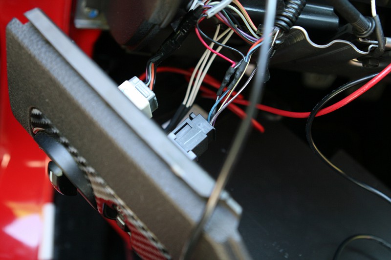
Dimmer:
Look for the red wire I added going into the heat-shrink and mating with the black wire with a white stripe - that is your dimmer adjustable 12V power:

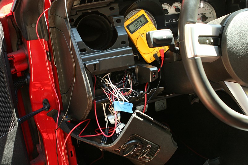
Chassis ground:
I used the bolt you see directly below my multi-meter - you see a white wire with black heat-shrink going to it:
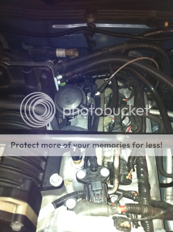
Boost line:
I stole this picture from Matt Henry on FnSweet...it is easier to see than mine is since I have a TVS. Thanks, Matt. Mine is identical, and I can provide a pic later if needed or if Matt doesn't want me harvesting his pics...
Coil trigger:
Most guys use the #8 coil plug, but with my TVS supercharger, #7 was easier to get to. You can use any of them. I used the number 7 coil-on-plug wire that was NOT red. I couldn't tell the color since it was faded, but it does have a stripe. I used #7 instead of #8 since it was easier to get to without removing the TVS intake and GT500 throttle body. #7 is on the driver's side and is the second cylinder from the firewall. I didn't take a pic because it was so tight I could barely fit my hands in there. In my case, that wire feeds the green "trigger" wire on my AutoMeter shift light.
The OBD-II connection is self-explanatory, and the AeroForce comes with the necessary cable. Plug and -play - almost - I'll get to that in a minute.
And the dimming rheostat...I needed it for my AutoMeter NV series boost gauge...and it was so bright it looked like a Martian Attack from the fast and furious...so I bought this:
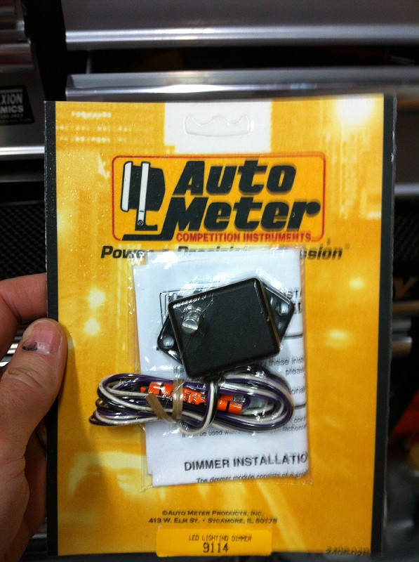
One black wire goes to ground on it (same chassis ground bolt described above), the violet wire goes to your dimmer wire (black with white stripe as described above) and the output (white wire from the rheostat) goes to the +12V lighting wire on the back of the gauge or gauges you wish to adjust brightness on.
For my boost gauge, I needed a 90 degree fitting to prevent kinking my boost line:

So...I ran all the wires through the SOS pillar pod and down through the dash:
That covers all the physical connections.
I wrapped electrical tape around each gauge to get a snug fit in the SOS pod, then I snapped it into place.
The re-installation of the SOS pillar is as easy as the OEM piece, since it is actually a modified OEM Ford piece. Mine was missing the cardboard rectangular stand-off, so I harvested the one from my original piece and hot-melt glued it in place. If you do this install, you will see what piece I mean. The SOS piece literally snaps in position.
Finished images:
Night-style:
SHIFT!!!!!!

So...why did I choose what I chose?
1) I like an analog, mechanical needle-style boost gauge vs. a digital one. I had one on my Dodge Omni GLH Turbo when I was 17. Tradition. The NV series was the closest I could find to the Roush "IndiGlo" dash cluster. It doesn't match, but it is close enough.
2) I could have used the shift-light feature of the AeroForce, or added a Raptor-claw, but I have a tube-style AutoMeter Digital Pro Shift System level 2 on my rice-burning 170 RWHP Superbike with air shifter, and I love it - so I wanted one on the 'Stang since it is what I am comfortable with. It has progressive warning if you put it in "run" mode (easily set into run if you push the right then left face buttons) and full time regualr bright light when not in run mode, it has multiple programmable shift points, short-shift auto gear change sequential advance if you drop 450 RPM during a run, over-rev flash, launch mode, changeable color selection (6 colors), Peak RPM recall, adjustable brightness. It rules. It requires a trigger set point (Pulses Per revolution) of .5 in the setup menu to do its thing.
3) The AeroForce Interceptor: I went with model CNF501 - again, to match the "green theme" as best I could. What can be said about the AeroForce - it does it all displays any OBD-II parameter the cars PCM sees. Pretty cool. There are two analog input wires on the AeroForce; I ran long extensions on those and zip-tied them under the car for future use.
I own an Innovate Motorsports Wideband setup already (on my SuperBike) and I have the bike jetted, so I may pull it and put it on the Stang, or I may just add the Bosch wideband adapter from AeroForce. If I harvest it off my bike, it will go in a Roush vent pod.
Big picture: You need a place to mount them. Popular options are the SOS pillar pods, the SOS, Saleen, or other branded center-dash pods, and of course the Roush air-vent pods.
I chose the SOS 3-pod pillar mounting option, which perfectly matches my interior.
Getting all the parts was a hassle: Jegs sent me a boost gauge that was mis-calibrated (it was on 1.5 PSI or so, which was unsat) so I had to exchange it; Stage 3 Motorsports said the 3 gauge pillar was "shipping from their other warehouse" but it drop-shipped direct from SOS, and when it arrived, it was a two-pod pillar...so I sent it back to SOS, and they forgot about it on account of a funeral, but eventually I got it all sorted out. For the Pièce de résistance, I ordered an AeroForce Interceptor from Maryland Speed, which was supposed to drop-ship from AeroForce, and it took 19 days to get in stock...it arrived yesterday - with a scratched lens and missing the silver bezel. I can't win.
I swear I am going to open up my own parts business and do things right. Real human tech support and the whole nine yards...AeroForce has no number anywhere to contact them...not on the box, in the instructions, on the website, etc. I e-mailed them, and their response was "will do". No "sorry about that, etc. I suppose you can be that way when you make awesome accessories that are in such great demand they are back-ordered.
Anyway, there is not much to it...so here we go.
I needed the following connections for the gauges I chose, and I will show where I sourced each of them:
- +12V switched power - back of radio: Gray / Yellow Pin 2 on the J1/C290D connector
- ~12V variable dimmer power (dash lighting circuit): Black / yellow striped wire behind factory headlight / foglamp rotary switch
- Chassis Ground - bolt adjacent to factory headlight switch
- Boost line - direct to vacuum line that runs from the IPTS sensor on the fuel rail to the intake manifold.
- Coil trigger
- OBD-II connection
- Dimming rheostat
Pics:
12V switched:
(I skipped showing behind the radio for the switched 12V which is pretty standard stuff. As always, all my connections are soldered and heat-shrunk, with no splices or add-a-fuses:
Dimmer:
Look for the red wire I added going into the heat-shrink and mating with the black wire with a white stripe - that is your dimmer adjustable 12V power:
Chassis ground:
I used the bolt you see directly below my multi-meter - you see a white wire with black heat-shrink going to it:
Boost line:
I stole this picture from Matt Henry on FnSweet...it is easier to see than mine is since I have a TVS. Thanks, Matt. Mine is identical, and I can provide a pic later if needed or if Matt doesn't want me harvesting his pics...
Coil trigger:
Most guys use the #8 coil plug, but with my TVS supercharger, #7 was easier to get to. You can use any of them. I used the number 7 coil-on-plug wire that was NOT red. I couldn't tell the color since it was faded, but it does have a stripe. I used #7 instead of #8 since it was easier to get to without removing the TVS intake and GT500 throttle body. #7 is on the driver's side and is the second cylinder from the firewall. I didn't take a pic because it was so tight I could barely fit my hands in there. In my case, that wire feeds the green "trigger" wire on my AutoMeter shift light.
The OBD-II connection is self-explanatory, and the AeroForce comes with the necessary cable. Plug and -play - almost - I'll get to that in a minute.
And the dimming rheostat...I needed it for my AutoMeter NV series boost gauge...and it was so bright it looked like a Martian Attack from the fast and furious...so I bought this:
One black wire goes to ground on it (same chassis ground bolt described above), the violet wire goes to your dimmer wire (black with white stripe as described above) and the output (white wire from the rheostat) goes to the +12V lighting wire on the back of the gauge or gauges you wish to adjust brightness on.
For my boost gauge, I needed a 90 degree fitting to prevent kinking my boost line:
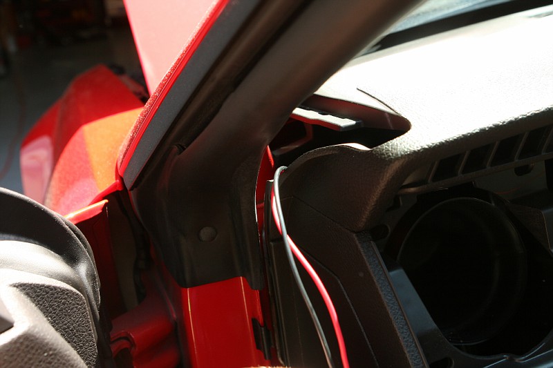
So...I ran all the wires through the SOS pillar pod and down through the dash:
That covers all the physical connections.
I wrapped electrical tape around each gauge to get a snug fit in the SOS pod, then I snapped it into place.
The re-installation of the SOS pillar is as easy as the OEM piece, since it is actually a modified OEM Ford piece. Mine was missing the cardboard rectangular stand-off, so I harvested the one from my original piece and hot-melt glued it in place. If you do this install, you will see what piece I mean. The SOS piece literally snaps in position.
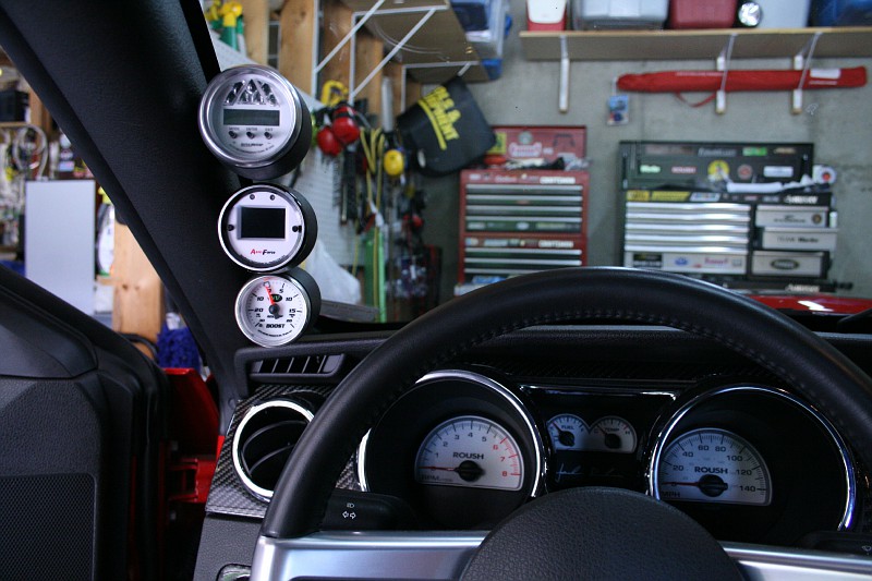
Finished images:
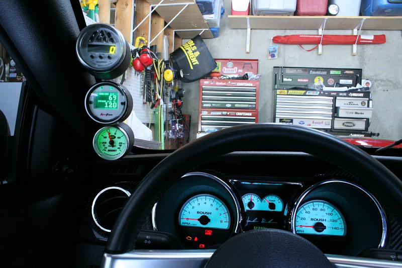
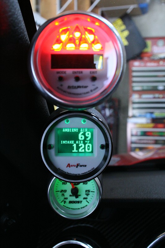
Night-style:
SHIFT!!!!!!
So...why did I choose what I chose?
1) I like an analog, mechanical needle-style boost gauge vs. a digital one. I had one on my Dodge Omni GLH Turbo when I was 17. Tradition. The NV series was the closest I could find to the Roush "IndiGlo" dash cluster. It doesn't match, but it is close enough.
2) I could have used the shift-light feature of the AeroForce, or added a Raptor-claw, but I have a tube-style AutoMeter Digital Pro Shift System level 2 on my rice-burning 170 RWHP Superbike with air shifter, and I love it - so I wanted one on the 'Stang since it is what I am comfortable with. It has progressive warning if you put it in "run" mode (easily set into run if you push the right then left face buttons) and full time regualr bright light when not in run mode, it has multiple programmable shift points, short-shift auto gear change sequential advance if you drop 450 RPM during a run, over-rev flash, launch mode, changeable color selection (6 colors), Peak RPM recall, adjustable brightness. It rules. It requires a trigger set point (Pulses Per revolution) of .5 in the setup menu to do its thing.
3) The AeroForce Interceptor: I went with model CNF501 - again, to match the "green theme" as best I could. What can be said about the AeroForce - it does it all displays any OBD-II parameter the cars PCM sees. Pretty cool. There are two analog input wires on the AeroForce; I ran long extensions on those and zip-tied them under the car for future use.
I own an Innovate Motorsports Wideband setup already (on my SuperBike) and I have the bike jetted, so I may pull it and put it on the Stang, or I may just add the Bosch wideband adapter from AeroForce. If I harvest it off my bike, it will go in a Roush vent pod.