ddd4114
forum member
It's probably a long shot that other people have tried to measure their roll centers and are willing to share, but I'd appreciate any tidbits of knowledge that anybody would like to post.
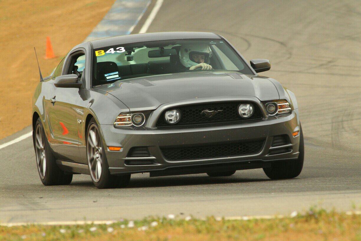
To provide some background, I have a 2011 GT with basically stock suspension. The only change I've made is camber plates to bring the angle out to a whopping -1 deg. The springs, dampers, bushings, etc. are exactly as they were from the factory. I've been doing HPDE events for a few years, and I've gotten to the point where I'd like to do some suspension work for two reasons. The first (and most obvious) reason is to improve grip and transient response, and the second is to stop shredding the outside edges of my expensive tires and lengthen their lives a bit. I'd like to start doing NASA TT this summer (hopefully in TTB), so I'm also looking for a solution that's cheap in terms of points and also for my wallet.
I could do the usual "replace the springs and shocks and see what happens" approach, but the nerdy engineer in me wanted to have a better understanding of the effects. Therefore, I decided to do some "quick" calculations that have left me scratching my head.
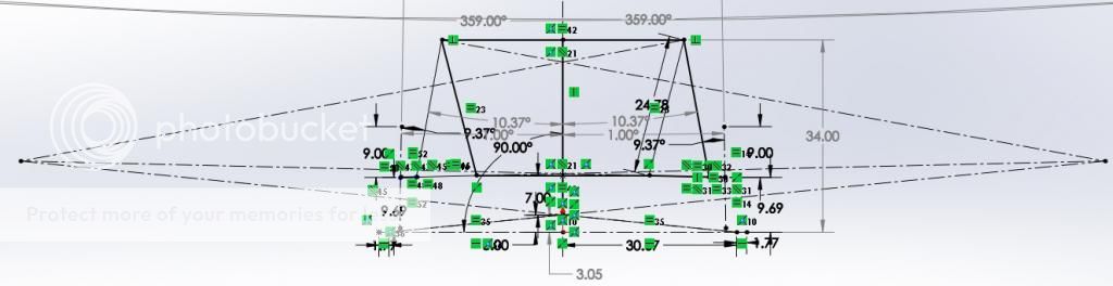
For now, I'm just looking at the car in steady-state cornering. I know it's a very narrow view of the whole picture, but it's a good and simple starting point. I spent a couple hours mapping out my suspension points to approximate my roll centers, and since I've never done this on a car with struts, I wasn't sure what to expect. Obviously my measurements can only be so good with a plumb-bob and a ruler, and since I'm neglecting bushing compliance, I'm not expecting a ton of accuracy. However, I've played around with my model enough that unless I made a significant measurement error, I think it's still in the ballpark.
Without any body roll, the roll center heights are pretty easy to find:
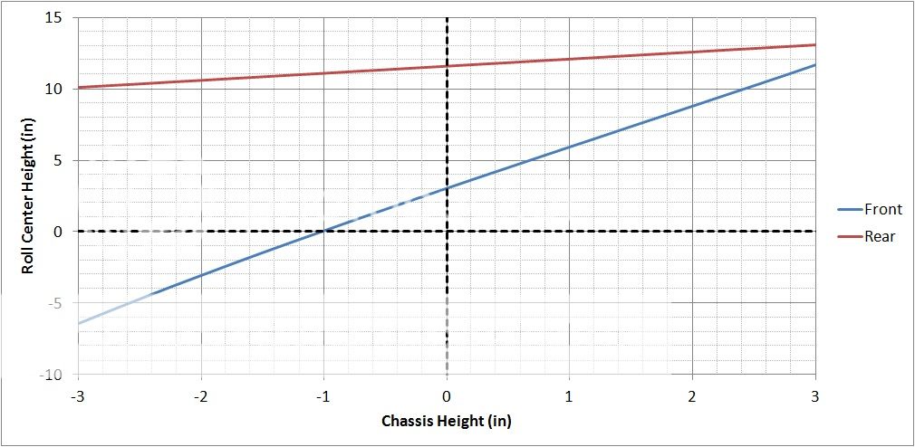
I expected the front roll center to move around a bit, but I didn't realize how significant it was. With my car at its current (stock) height, the roll center is about 3" off the ground, but if I lower it by only 1", it goes right down to ground level.
Once I looked at the effect of roll, strange things happened. With the car at stock height, I got a pretty clear trend:
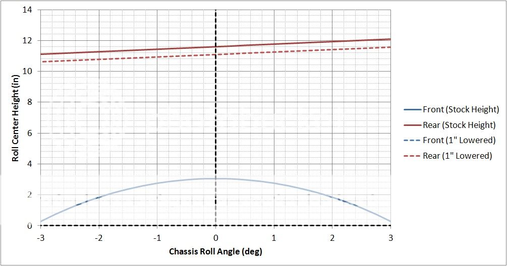
However, once I reduced the chassis height by 1", the roll center was basically impossible to find with any roll angle more than ~1 deg. Basically, the lines connecting the instant centers to the contact patches became almost parallel, so the roll center quickly moved off the screen. I bet if I reduced the chassis height by another inch, I could move the roll center to the moon.
The overall result is that the spring rates are just about meaningless in roll. Since the front roll center drops so much as the car is lowered, you have to run crazy high rates to actually increase front roll stiffness appreciably, and that isn't such a great idea for mechanical grip. Furthermore, since the roll axis becomes steeper, the lateral load transfer distribution will immediately shift to the rear by ~3%. That might not be such a bad thing considering the car pushes pretty badly, but if I ever want to shift the distribution back toward the front, it's basically impossible to do it with springs.
The anti-roll bars are already fairly stiff from the factory, and it does seem possible to effectively reduce body roll and manipulate LLTD by playing with their diameters. However, they would have to be a LOT stiffer to make a significant improvement by themselves - probably at least 1/8" larger OD, and I'm sure bushing compliance and even chassis strength might become a concern at that point. Stiffer bars also won't address other performance issues with the car; for example, they won't prevent it from standing on its nose under braking.
Has anybody else tried measuring this stuff? Do the trends I've posted seem reasonable? I've checked my work, but if I made a huge mistake somewhere, I'd like to avoid chasing my tail too much. I know that many people on here have modified their suspensions, but since it's easy to fall for the placebo effect with different shock tuning and natural frequencies, I'm hoping to get some objective information.
It seems like if I want to run the car in TTB and have a decent suspension setup, I might be looking for a unicorn. Whatever the case, I'll try to find some kind of acceptable compromise and see what's possible. I'm just hoping that a little measurement work up front will save me a lot of guesswork and (expensive) track time down the road.
Thanks.
To provide some background, I have a 2011 GT with basically stock suspension. The only change I've made is camber plates to bring the angle out to a whopping -1 deg. The springs, dampers, bushings, etc. are exactly as they were from the factory. I've been doing HPDE events for a few years, and I've gotten to the point where I'd like to do some suspension work for two reasons. The first (and most obvious) reason is to improve grip and transient response, and the second is to stop shredding the outside edges of my expensive tires and lengthen their lives a bit. I'd like to start doing NASA TT this summer (hopefully in TTB), so I'm also looking for a solution that's cheap in terms of points and also for my wallet.
I could do the usual "replace the springs and shocks and see what happens" approach, but the nerdy engineer in me wanted to have a better understanding of the effects. Therefore, I decided to do some "quick" calculations that have left me scratching my head.
For now, I'm just looking at the car in steady-state cornering. I know it's a very narrow view of the whole picture, but it's a good and simple starting point. I spent a couple hours mapping out my suspension points to approximate my roll centers, and since I've never done this on a car with struts, I wasn't sure what to expect. Obviously my measurements can only be so good with a plumb-bob and a ruler, and since I'm neglecting bushing compliance, I'm not expecting a ton of accuracy. However, I've played around with my model enough that unless I made a significant measurement error, I think it's still in the ballpark.
Without any body roll, the roll center heights are pretty easy to find:
I expected the front roll center to move around a bit, but I didn't realize how significant it was. With my car at its current (stock) height, the roll center is about 3" off the ground, but if I lower it by only 1", it goes right down to ground level.
Once I looked at the effect of roll, strange things happened. With the car at stock height, I got a pretty clear trend:
However, once I reduced the chassis height by 1", the roll center was basically impossible to find with any roll angle more than ~1 deg. Basically, the lines connecting the instant centers to the contact patches became almost parallel, so the roll center quickly moved off the screen. I bet if I reduced the chassis height by another inch, I could move the roll center to the moon.
The overall result is that the spring rates are just about meaningless in roll. Since the front roll center drops so much as the car is lowered, you have to run crazy high rates to actually increase front roll stiffness appreciably, and that isn't such a great idea for mechanical grip. Furthermore, since the roll axis becomes steeper, the lateral load transfer distribution will immediately shift to the rear by ~3%. That might not be such a bad thing considering the car pushes pretty badly, but if I ever want to shift the distribution back toward the front, it's basically impossible to do it with springs.
The anti-roll bars are already fairly stiff from the factory, and it does seem possible to effectively reduce body roll and manipulate LLTD by playing with their diameters. However, they would have to be a LOT stiffer to make a significant improvement by themselves - probably at least 1/8" larger OD, and I'm sure bushing compliance and even chassis strength might become a concern at that point. Stiffer bars also won't address other performance issues with the car; for example, they won't prevent it from standing on its nose under braking.
Has anybody else tried measuring this stuff? Do the trends I've posted seem reasonable? I've checked my work, but if I made a huge mistake somewhere, I'd like to avoid chasing my tail too much. I know that many people on here have modified their suspensions, but since it's easy to fall for the placebo effect with different shock tuning and natural frequencies, I'm hoping to get some objective information.
It seems like if I want to run the car in TTB and have a decent suspension setup, I might be looking for a unicorn. Whatever the case, I'll try to find some kind of acceptable compromise and see what's possible. I'm just hoping that a little measurement work up front will save me a lot of guesswork and (expensive) track time down the road.
Thanks.