This thread will serve as the installation guide for 05-10 Single turbo kit. It will also be an open thread for guys to ask questions about the install and we will answer those questions here for others to see and reference. Figured this would be the easiest and most beneficial way to gather that info all in one place.
The kit can be installed on jack stands or on a lift, using hand tools. Recommend two people for the install and it can be done in 5-6 hours.
Recommended tuners are Pro-Dyno, Mid Atlantic Performance and "Lito" MDS www.tudyno.com
Below is a list of tools and materials that we recommend for the install.
Anti seize
Copper RTV sealant
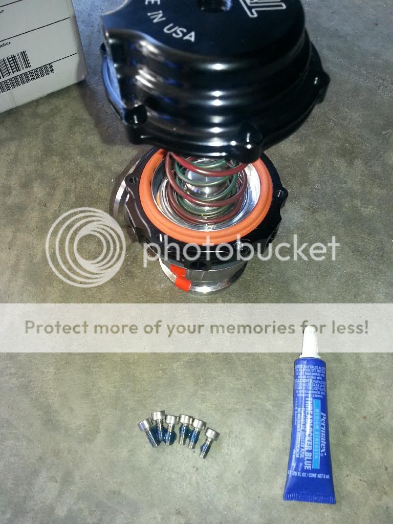
Blue locktite
Locktite 567 thread sealant (liquid Teflon)
An wrenches or adjustable smooth jaw wrenches
(If running the rear o2 sensors the you will need o2 extensions)
Drain pan
Jack stands or lift
Assorted hand tools wrenches and sockets
Razor blade
Zip ties
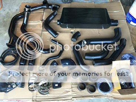
Single kit parts list.
-CT4X T4/3"vband gen2 oil-less turbo
-Passenger header J pipe with flex coupler
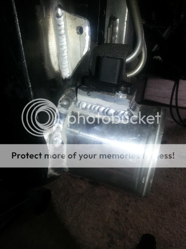
-Driver side feed pipe with merge, T4 flange and wastegate mount
-Down pipe with 3" cutout/cap and Y split
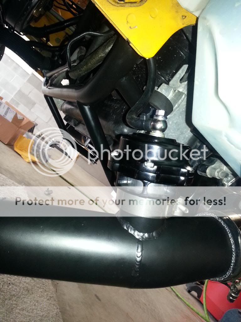
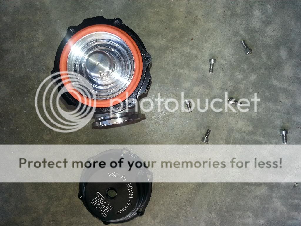
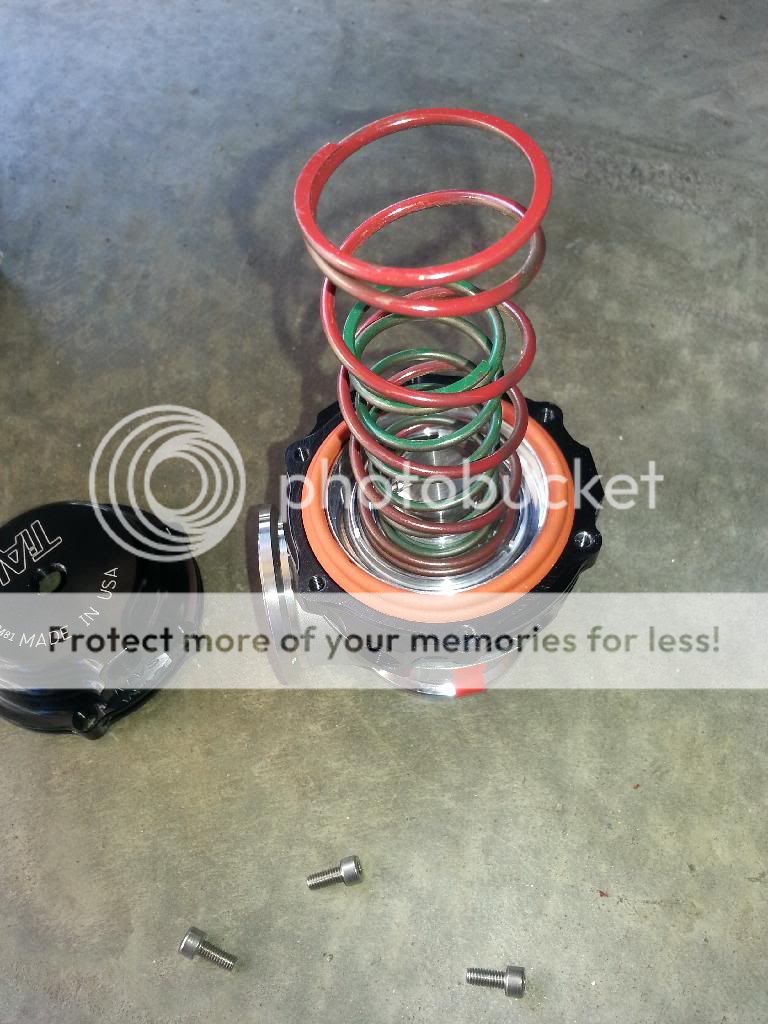
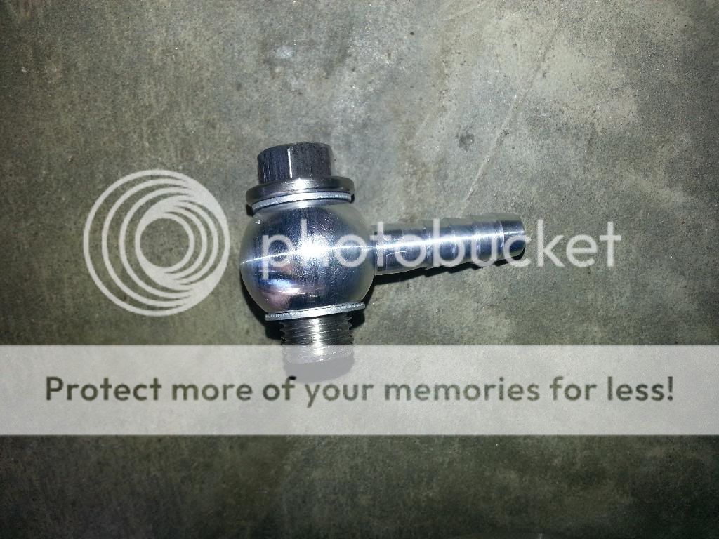
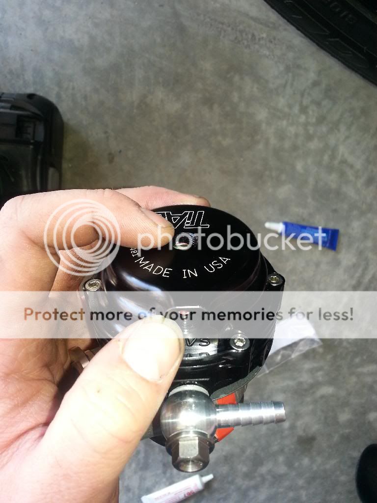
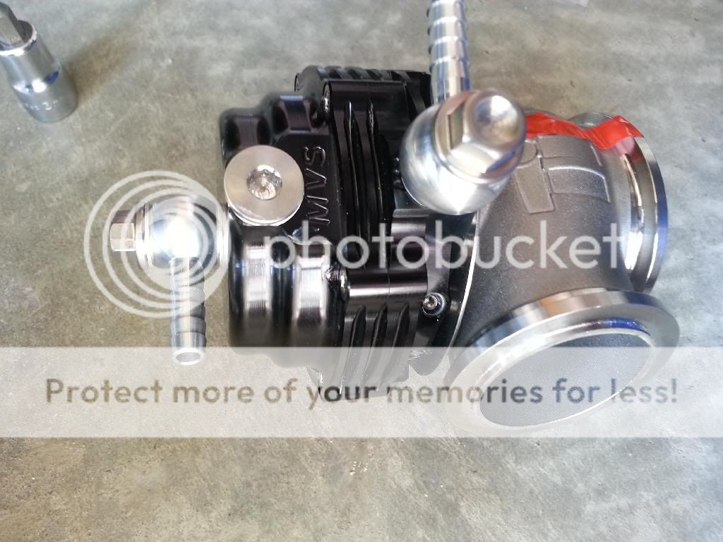
-S&H Performance 50mm blow off valve kit
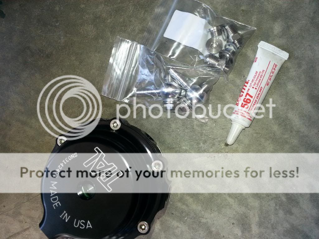
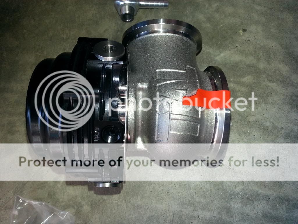
-Tial MVS 38mm vband wastegate kit
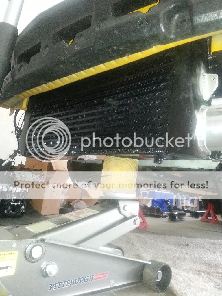
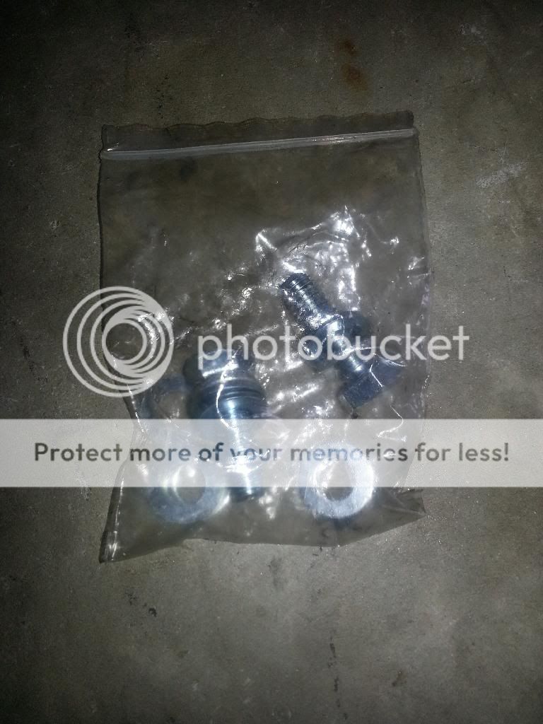
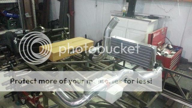
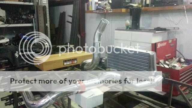
-Intercooler with mounting bolts
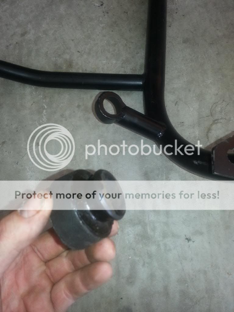
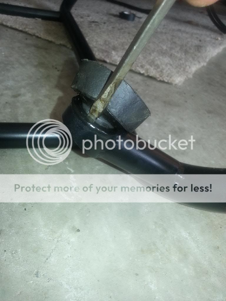
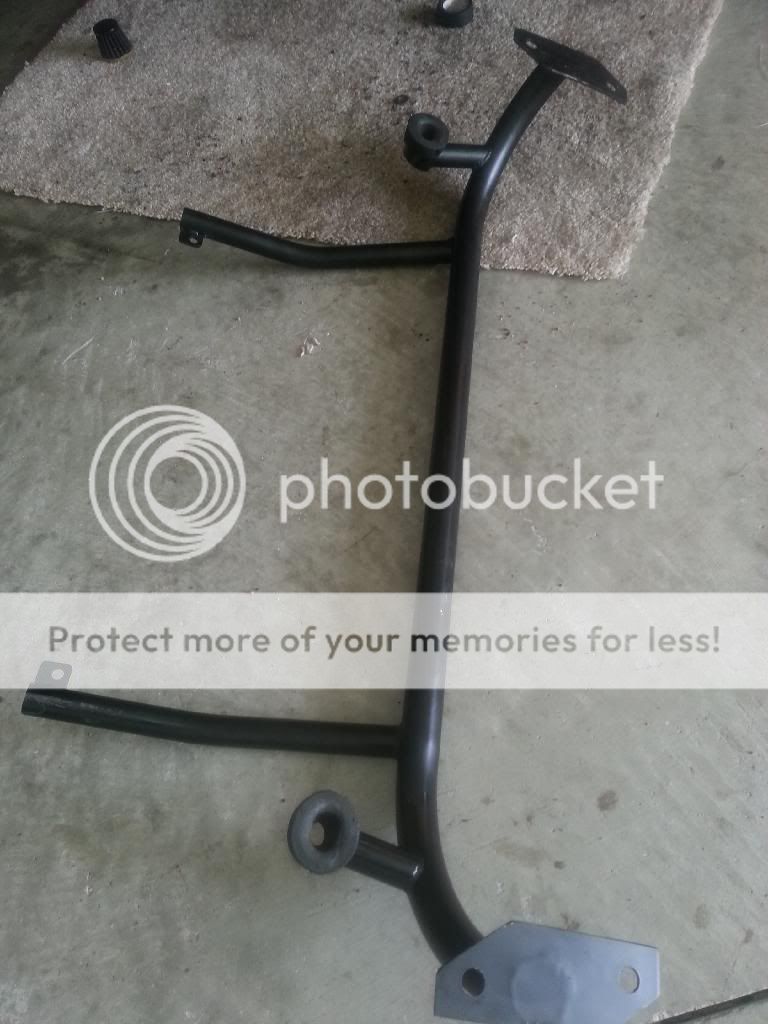
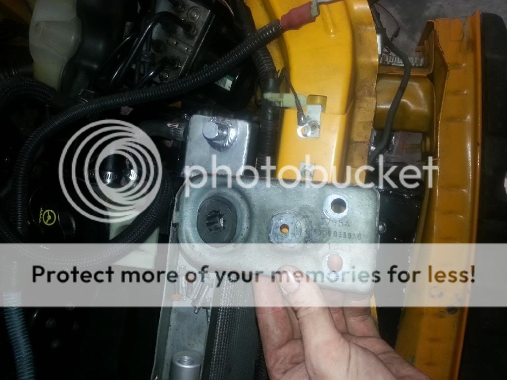
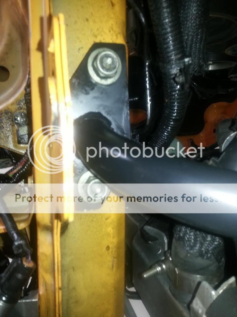
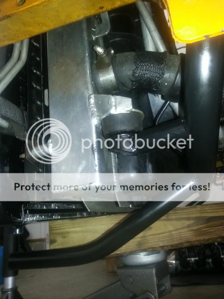
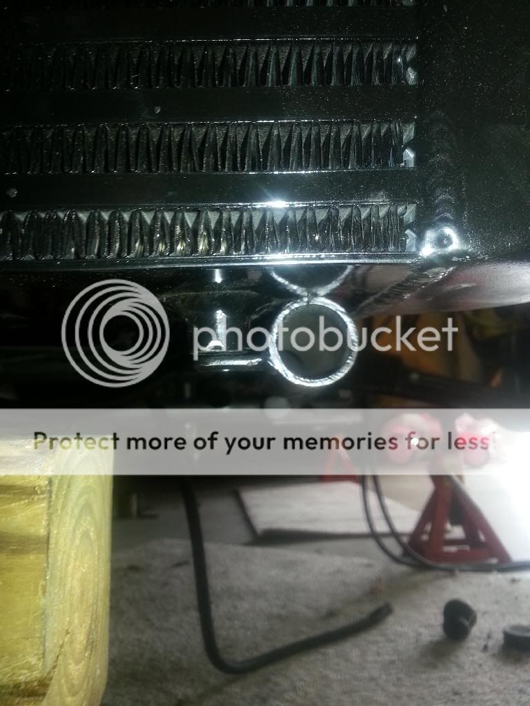
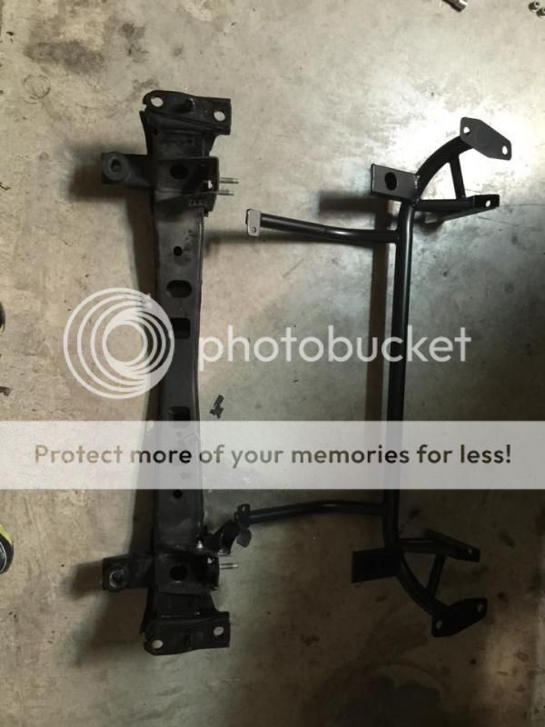
-Radiator/intercooler/swaybar support brace
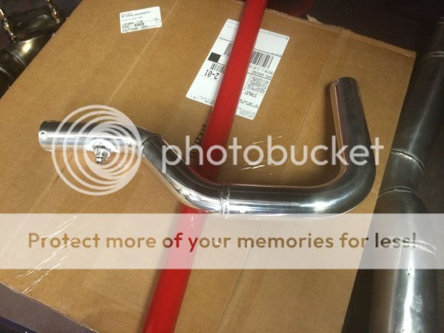
-3.5" aluminum pipes from intercooler to throttle body x 2
-3" aluminum pipe from turbo to intercooler x 3
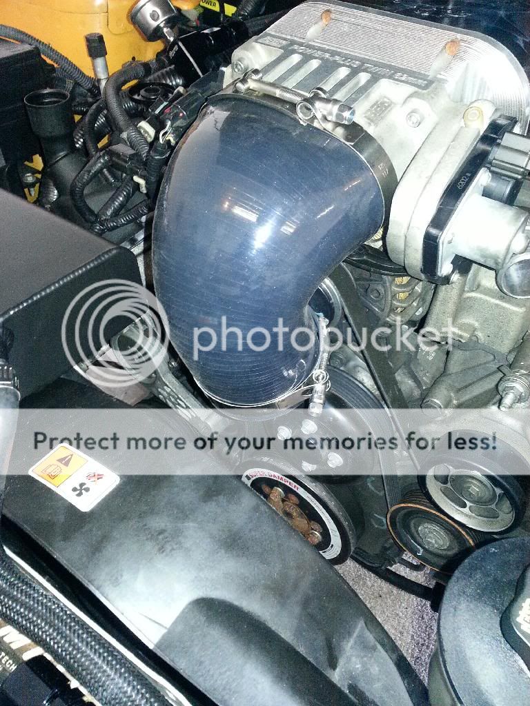
-4.5" to 3.5" 90deg silicone coupler to throttle body
-3.5" 90deg silicone coupler
-3.5" straight coupler
-3" 90deg silicone coupler
-3" straight silicone coupler x 2
-2.5" straight silicone coupler
-4" to 3" straight coupler
-3" v-band clamp
-2.5" v-band clamp
-2.5" t-bolt clamp x 2
-3" t-bolt clamp x 7
-3.5" t-bolt clamp x 5
-4.5" t-bolt clamp
-4" t-bolt clamp
-1.5" t-bolt clamp x 2
-PMAS HPX-E mass air meter and wire extension (plug and play)
-Radiator hose adaptor for water return (05/06) or Upper Radiator pipe for (07-10)
-Air filter
-4" to 3" aluminum pipe (filter to turbo compressor cover)
-Roll of black fiberglass heat wrap 50ft
-6mm black silicone boost/vac tubing 12ft
-T4 turbo blanket
-Water line kit (6an hose, hose ends and fittings)
General installation Notes:
Many of the steps can be done in any order.
Before you start:
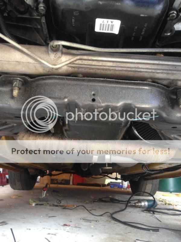
As always ensure the car is properly supported on a lift or jackstands and disconnect the negative battery terminal.
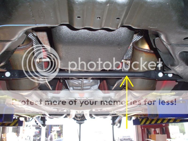
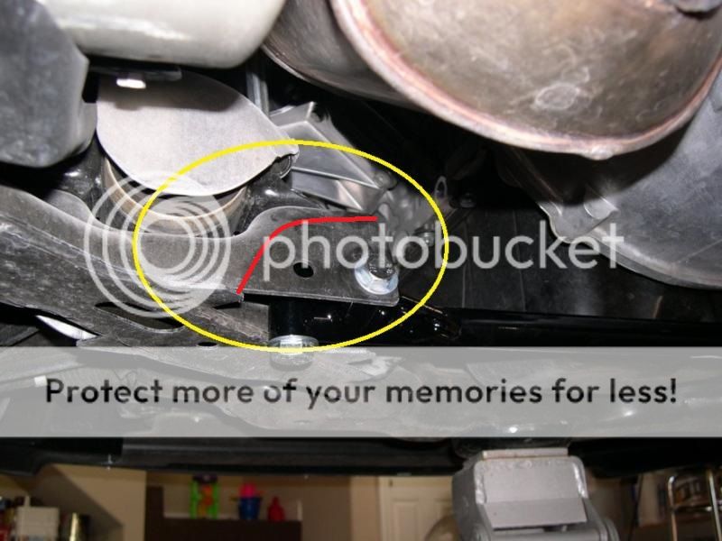
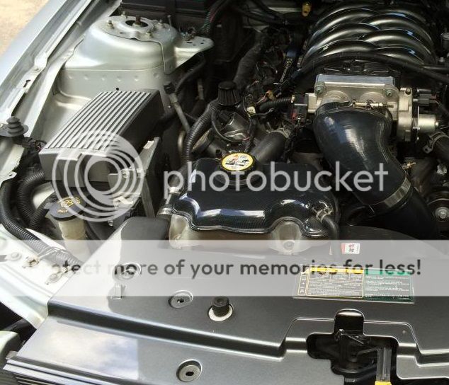
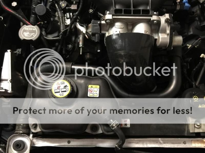
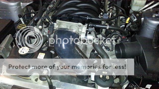
Remove the factory mid-pipe, you will reuse the studs and nuts and clamps. Remove the intake and airbox.
Drain the coolant into a drain pan or bucket, ensure the container is clean if you plan to reuse the coolant at the end.
Your ready to begin!
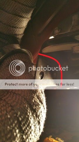
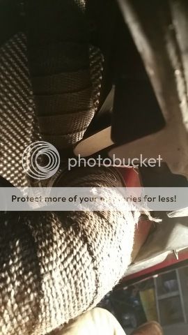
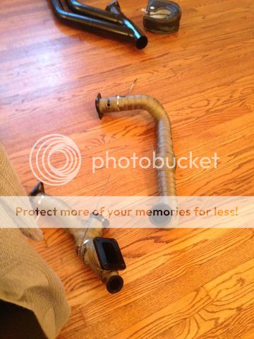
Heat Wrap:
We recommend wrapping all pre turbo hot side piping. Some may use stainless steel metal zipties to attach it which you can get at your local home depot or Lowe's but they can be a pain, we have found worm gear clamp to work a little better.
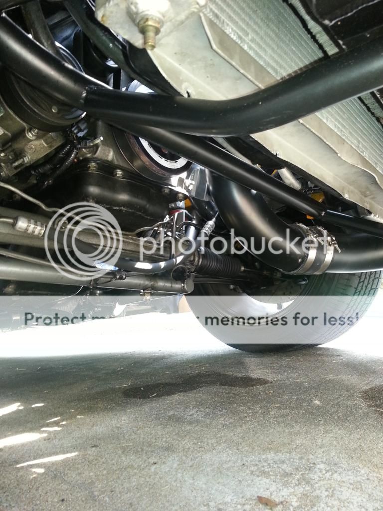
We also recommend wrapping the first cold side pipe that goes from the turbo outlet towards the passenger side of the car and up over the k member since this pipe is closest to exhaust piping. Make sure you leave enough room for the silicone coupler to slip over the pipe on each end if you do.
Turbo blanket:
The turbine blanket will help keep heat in the turbine and promote spool, it is not mandatory to be used and some may choose to leave it off. Leaving it off will not affect anything or cause excess heat under the car. We include a blanket for your convenience.
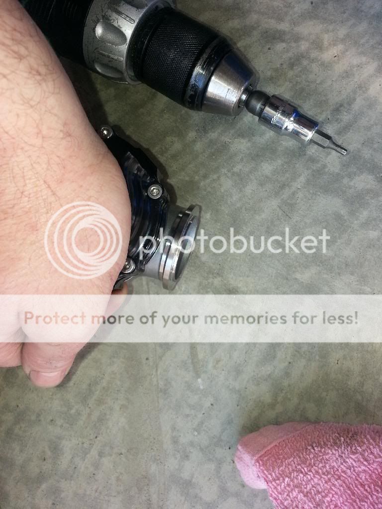
V-band and T-bolt clamps:
These clamps don't need gorilla torqued down to get a good seal, do not use power tools or you can break them. For the v-bands a good layer of copper rtv on the flanges and get the clamp on and nut started and snug tight with a wrench and you will have a good seal. For the T-bolts, you want to place them on the silicone coupler and pipe even with and close to the rolled bead but not on top of it. And again snug tight by hand with a wrench do not over torque or you will strip the threads and break the clamp.
The kit can be installed on jack stands or on a lift, using hand tools. Recommend two people for the install and it can be done in 5-6 hours.
Recommended tuners are Pro-Dyno, Mid Atlantic Performance and "Lito" MDS www.tudyno.com
Below is a list of tools and materials that we recommend for the install.
Anti seize
Copper RTV sealant
Blue locktite
Locktite 567 thread sealant (liquid Teflon)
An wrenches or adjustable smooth jaw wrenches
(If running the rear o2 sensors the you will need o2 extensions)
Drain pan
Jack stands or lift
Assorted hand tools wrenches and sockets
Razor blade
Zip ties
Single kit parts list.
-CT4X T4/3"vband gen2 oil-less turbo
-Passenger header J pipe with flex coupler
-Driver side feed pipe with merge, T4 flange and wastegate mount
-Down pipe with 3" cutout/cap and Y split
-S&H Performance 50mm blow off valve kit
-Tial MVS 38mm vband wastegate kit
-Intercooler with mounting bolts
-Radiator/intercooler/swaybar support brace
-3.5" aluminum pipes from intercooler to throttle body x 2
-3" aluminum pipe from turbo to intercooler x 3
-4.5" to 3.5" 90deg silicone coupler to throttle body
-3.5" 90deg silicone coupler
-3.5" straight coupler
-3" 90deg silicone coupler
-3" straight silicone coupler x 2
-2.5" straight silicone coupler
-4" to 3" straight coupler
-3" v-band clamp
-2.5" v-band clamp
-2.5" t-bolt clamp x 2
-3" t-bolt clamp x 7
-3.5" t-bolt clamp x 5
-4.5" t-bolt clamp
-4" t-bolt clamp
-1.5" t-bolt clamp x 2
-PMAS HPX-E mass air meter and wire extension (plug and play)
-Radiator hose adaptor for water return (05/06) or Upper Radiator pipe for (07-10)
-Air filter
-4" to 3" aluminum pipe (filter to turbo compressor cover)
-Roll of black fiberglass heat wrap 50ft
-6mm black silicone boost/vac tubing 12ft
-T4 turbo blanket
-Water line kit (6an hose, hose ends and fittings)
General installation Notes:
Many of the steps can be done in any order.
Before you start:
As always ensure the car is properly supported on a lift or jackstands and disconnect the negative battery terminal.
Remove the factory mid-pipe, you will reuse the studs and nuts and clamps. Remove the intake and airbox.
Drain the coolant into a drain pan or bucket, ensure the container is clean if you plan to reuse the coolant at the end.
Your ready to begin!
Heat Wrap:
We recommend wrapping all pre turbo hot side piping. Some may use stainless steel metal zipties to attach it which you can get at your local home depot or Lowe's but they can be a pain, we have found worm gear clamp to work a little better.
We also recommend wrapping the first cold side pipe that goes from the turbo outlet towards the passenger side of the car and up over the k member since this pipe is closest to exhaust piping. Make sure you leave enough room for the silicone coupler to slip over the pipe on each end if you do.
Turbo blanket:
The turbine blanket will help keep heat in the turbine and promote spool, it is not mandatory to be used and some may choose to leave it off. Leaving it off will not affect anything or cause excess heat under the car. We include a blanket for your convenience.
V-band and T-bolt clamps:
These clamps don't need gorilla torqued down to get a good seal, do not use power tools or you can break them. For the v-bands a good layer of copper rtv on the flanges and get the clamp on and nut started and snug tight with a wrench and you will have a good seal. For the T-bolts, you want to place them on the silicone coupler and pipe even with and close to the rolled bead but not on top of it. And again snug tight by hand with a wrench do not over torque or you will strip the threads and break the clamp.
Last edited: