Planning a Ford Racing “Aluminator” Build with associated mods over the winter

Scott

Senior Member
Joined
Nov 17, 2009
Posts
2,337
Reaction score
44
Location
King City, Ontario, Canada
Valve Covers

Moroso Fabricated Aluminum Valve Covers are part number 68388.

A 7L1Z-6C535-AA VCT Solenoid Seal to Valve Cover and a 7L1Z-6584-A Gasket were installed on the right hand Valve Cover.


The right hand camshaft lobes were liberally coated with Comp Cams Cam and Lifter Installation Lube part number 152 – 4 FL. OZ.


RTV Ultra Black Gasket Maker was also applied to the matching joints between the right hand Cylinder Heads and the Front Cover.


The right hand valve cover was installed and the stainless steel Allen Key Head Cap Screws were tightened to 89 in-lbs following the shop manual sequence.


Before installation of the left hand valve cover a small tab that secures the wiring harness needed to be removed to allow for supercharger belt clearance. As a cutting guide, from the timing cover I traced the contour of the timing cover on the underside of the valve cover below the tab to be removed.

Tab marked for removal (picture from underside).


Tab removed


A 7L1Z-6C535-AA VCT Solenoid Seal to Valve Cover and a 7L1Z-6584-B Gasket were installed on the left hand Valve Cover.


Someone who shall remain nameless forgot to take a picture of the left hand Valve Cover Gasket before the Valve Cover was installed. :asshat:

Similar to the right hand camshaft lobes, the left hand camshaft lobes were liberally coated with Comp Cams Cam and Lifter Installation Lube.


RTV Ultra Black Gasket Maker was also applied to the matching joints between the left hand Cylinder Heads and the Front Cover.


The left hand valve cover was installed and the stainless steel Allen Key Head Cap Screws were tightened to 89 in-lbs following the shop manual sequence.


Scott

Senior Member
Joined
Nov 17, 2009
Posts
2,337
Reaction score
44
Location
King City, Ontario, Canada
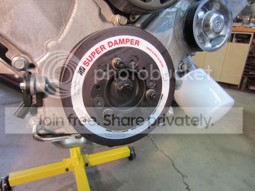
ATI Super Damper

ATI Super Damper part number 918039 was installed using a process combined from Ford, ATI and ARP instructions. Motorocraft High Temperature Nickel Anti-Seize Lubricant part number ZL-2, ARP Ultra-Torque Fastener Assembly Lubricant part number 100-9910, Permatex Medium Strength Blue Thread Locker part number 24240 and RTV Ultra Black Gasket Maker part number 59803 were used in the Damper installation.
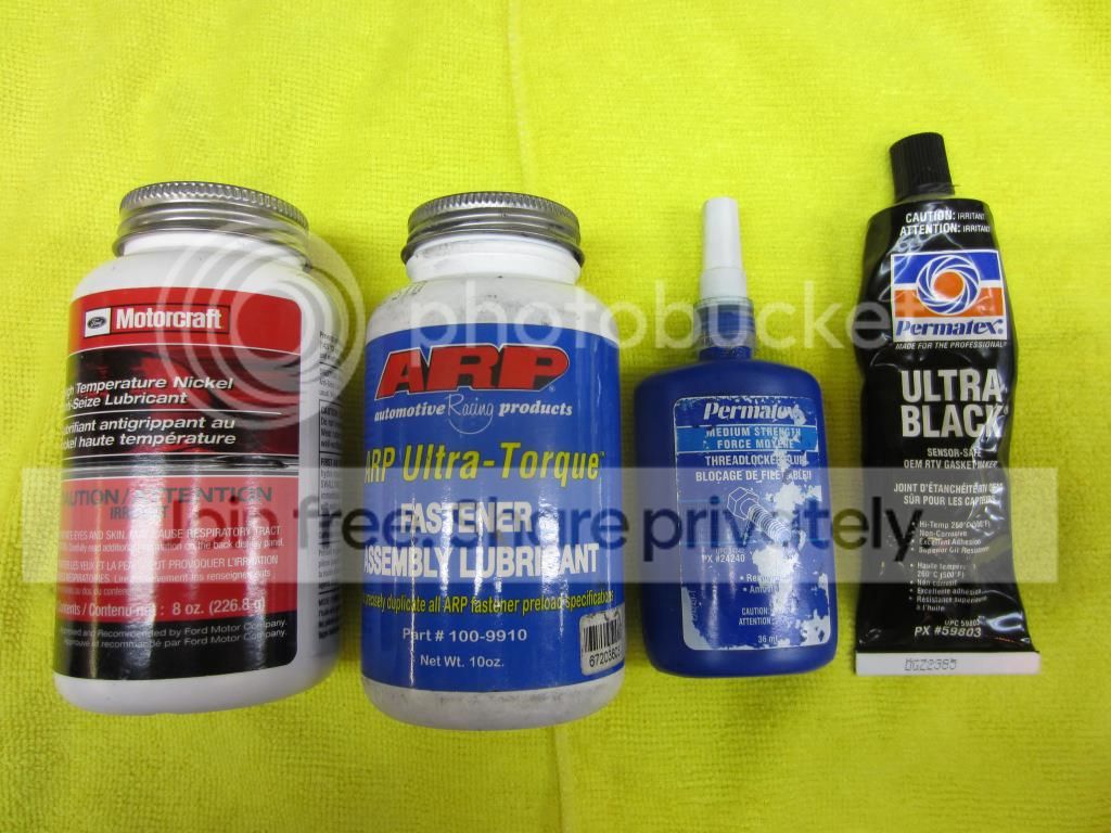
The Crankshaft snout and Woodruff key was checked yet again for any burrs.

Two M10 x 1.0 x 60mm bolts were installed in the transmission end of the Crankshaft to be used with a steel bar (aka large screwdriver) to secure the Crankshaft when tightening the ARP damper bolt.


ATI Washer part number 954078 supplied with the Super Damper was installed.


A thin coating of Motorcraft High Temperature Nickel Anti-Seize Lubricant part number ZL-2 was applied to the Crankshaft snout.


RTV Ultra Black Gasket Maker was applied to the Woodruff key slot on the Damper Hub.


The Hub was aligned with the Woodruff Key and pushed on with an install tool that consisted of a 6” length of 12mm x 1.5 threaded rod, a washer, 3 nuts, a 2” diameter Fender washer, and a INA D1-HLA Bearing.


ARP Ultra-Torque Assembly Lubricant was applied to the threads on the ARP bolt, the underhead of the bolt and the ARP washer where the washer contacts the Hub.


While securing the rear of the Crankshaft from movement the ARP Bolt part number 206-1001 was tightened to 100 ft-lbs using a 19mm 12 point socket.


ATI uses two indent dimples to indicate the proper alignment of the Damper to the Hub. This picture illustrates on the left the Damper indent dimple and on the right the Hub indent dimple.


Once the Hub and Damper indent dimples are aligned, start the three 12-point 3/8” cap screws through the Damper and into the Hub. Use medium strength blue thread locker on the threads. DO NOT pull down tight on the Damper.


Start the six countersunk flathead screws in the remaining holes using medium strength blue thread locker on the threads. Draw the Damper assembly into the hub evenly.

Tighten the three 12 point 3/8” cap screws to 30 ft-lbs and the six countersunk flathead screws to 16 ft-lbs (21.6 Nm) using a T40 Torx Plus Bit. (Note: a Torx T40 Bit is the wrong size; a T40 Plus Bit is required).


T40 Torque Plus Bit


Super Damper installed.
 

Scott

Senior Member
Joined
Nov 17, 2009
Posts
2,337
Reaction score
44
Location
King City, Ontario, Canada
Getting close to install. Looking good!

Looking great!!


Thanks guys!

I am starting to see light at the end of the tunnel. Engine swap is scheduled to start May 27th.

Once the old engine and transmission are out a few things need to be transferred – Fuel Rail Fittings, COPS, Throttle Body, Alternator, Power Steering Pump, AC Compressor, ARH LT’s, Starter, Belt Tensioner, and of course the Vortech Supercharger. Some mods are scheduled for the 5R55 when it is out – Hardened Input Shaft, 3rd and 4th Gear Servo Kits and a Multi Disk Circle D Specialties Converter.

Looking forward to putting the engine into the back of my Escape (this should be fun) to take it to the shop.
 

Timmbo

Senior Member
Joined
Jan 17, 2011
Posts
2,067
Reaction score
0
Location
TN
Wow. You should be writing service manuals. Love all the details! This has been a fun read on my lunch break. Wish I had time to put into a build. With my family and my job as the ambulance fleet manager for a major hospital, finding time for a build and getting it done in a timely manor is near impossible. Congrats on your build. I currently have Brenspeed building a B326 stroker for my ride. Hope to be enjoying the car again within the next month.

 

Scott

Senior Member
Joined
Nov 17, 2009
Posts
2,337
Reaction score
44
Location
King City, Ontario, Canada
Wow. You should be writing service manuals. Love all the details! This has been a fun read on my lunch break. Wish I had time to put into a build. With my family and my job as the ambulance fleet manager for a major hospital, finding time for a build and getting it done in a timely manor is near impossible. Congrats on your build. I currently have Brenspeed building a B326 stroker for my ride. Hope to be enjoying the car again within the next month.

Thanks and good luck with the B326!
 

Scott

Senior Member
Joined
Nov 17, 2009
Posts
2,337
Reaction score
44
Location
King City, Ontario, Canada
Fuel Rails and Injectors

The fuel rail end O-Rings on the Ford Racing 60 LB/HR Fuel Injectors part number M-9593-LU60 were lubricated with fresh engine oil and carefully pressed into the Fore Fuel Rails.


The intake end O-Rings on the right hand Fore Fuel Rail were lubricated with fresh engine oil and the Fuel Injectors carefully seated into the Ford Racing Intake Manifold part number M-9424-463V.


The two stainless steel cap screws that secure the right hand fuel rail were tightened with a 5mm bit to 89 in-lbs.


The intake end O-Rings on the left hand Fore Fuel Rail were lubricated with fresh engine oil and the Fuel Injectors carefully seated into the Ford Racing Intake Manifold.


The two stainless steel cap screws that secure the left hand fuel rail were tightened with a 5mm bit to 89 in-lbs.


Intake will be installed once the engine has been transported to Matt D at DaSilva Racing.
 

Scott

Senior Member
Joined
Nov 17, 2009
Posts
2,337
Reaction score
44
Location
King City, Ontario, Canada
Nice to see it's getting close & that you are putting in the fuel system now. Looks good.

Rick, not ready yet to put in the return style system. I already have Fore Fuel Rails on my car, so I will have the new Fore Rails on the FRPP Intake and just transfer over my fuel fittings for the time being. The plan is to install the return style system during the engine break-in period and of course before the power tune.
 

Scott

Senior Member
Joined
Nov 17, 2009
Posts
2,337
Reaction score
44
Location
King City, Ontario, Canada
Wired the Meziere Electric Coolant Pump

Wired the electric Meziere Coolant Pump part number WP346S and the Relay Kit part number WIK346 in preparation for the motor swap. Soldered all the connections and enclosed the wires in ¼” spiral wrap. Temporarily stole the use of a “key-on-source” connection to test the circuit. Need one more 14-16 gauge wire tap before I can call it done.

This shows the “key-off” state with no power.


And this illustrates “key-on” and we have power (ok, I see the battery needs to be topped up).


Scott

Senior Member
Joined
Nov 17, 2009
Posts
2,337
Reaction score
44
Location
King City, Ontario, Canada
Wired the Meziere Electric Coolant Pump - Continued

A trip to Princess Auto for a T-Tap and the key-on-source for the coolant pump wiring is now complete.


Scott

Senior Member
Joined
Nov 17, 2009
Posts
2,337
Reaction score
44
Location
King City, Ontario, Canada
Coolant Crossover, Thermostat and Thermostat Housing

Installed the Coolant Crossover part number 7R3E-8C369-AD, Coolant Crossover Bolts part number W710925-S437, Thermostat Housing part number 7R3Z-8592-A, Thermostat Housing O-Ring part number F1VY-8255-A (Motorcraft RG-571), two Thermostat Housing Bolts part number W503279-S437 and a Hypertech 160 Degree Thermostat part number HYP1011. Coolant Crossover and Thermostat Housing Bolts were tightened to 89 in-lbs.


To provide clearance for the Ford Racing Intake it is necessary to eliminate the Vortech spacer that rotates the thermostat housing snout a few degrees clockwise. I cut the snout on an angle, rotated it 180 degrees and had it welded back on. If my “guestimate” angle is correct the radiator hose will now pass through without the spacer. I have my fingers crossed!

Vortech Spacer


Cut T-Stat Housing


Welded T-Stat Housing


Placed the Hypertech Thermostat in the crossover.


Dipped the O-Ring in engine coolant and splashed a little extra coolant around.


Slipped the Thermostat Housing on and tighten the two bolts to 89 in-lbs.


Complete Coolant Crossover Assembly


Prior to removing the Vortech Spacer the Intake Manifold rested on the Thermostat Housing and did not mate with the Cylinder Heads.


With the Vortech Spacer removed and the Thermostat Housing modified for correct Radiator Hose routing the Intake Manifold now mates properly with the Cylinder Heads.


Scott

Senior Member
Joined
Nov 17, 2009
Posts
2,337
Reaction score
44
Location
King City, Ontario, Canada
Now What?

Guess what I am getting ready to do?


Ready to remove from the engine stand and install the Engine to Transmission Rear Plate and the Flex Plate.
 

Scott

Senior Member
Joined
Nov 17, 2009
Posts
2,337
Reaction score
44
Location
King City, Ontario, Canada
Engine off of the Stand…. Finally!

Lowered the engine off the stand and to the ground for the first time since February 11th.


Slipped on the automatic specific engine to transmission spacer plate part number 1L2Z-7007-BA


PRW Platinum Series SFI-Rated Flexplate part number 1828111 and ARP Flexplate Bolts part number 254-2901. (Please note the PRW box says 6 bolt, but as you can see the Flexplate is in fact 8 bolt.)


Trial fitting the Flexplate onto the Circle D Specialties multi-disk torque converter. Marked the Flexplate with correct bolt holes for reference during transmission installation.


Circle D Specialties 5R55 Pro Series Stage III 245mm Torque Converter.


Flexplate trial fitted to Crankshaft. There were a few burs around the Flexplate bolt holes that need to be addressed before installation.


Support us!

Support Us - Become A Supporting Member Today!

Click Here For Details

Back
Top