You are using an out of date browser. It may not display this or other websites correctly.
You should upgrade or use an alternative browser.
You should upgrade or use an alternative browser.
4.6L 3V Build
- Thread starter tmcolegr
- Start date
tmcolegr
It's All About the Build
No RTV. They bolt directly to the cylinder heads. Might want to run a flat file over them to make sure there are no high spots.
Thanks for the heads up, I'll be sure to do that.
NastyStang113
Made in U.S.A.
More great stuff, keep up the good work!
1SickRedfire
forum member
Interesting...so no need to prime the tensioners with a garden sprayer...
Interesting...so no need to prime the tensioners with a garden sprayer...
I must have missed that. Where did it say that?
US-1
Banned
Interesting...so no need to prime the tensioners with a garden sprayer...
Oh I'm sorry...that's in incorrect answer. But thanks for playing and we've got some really crappy consolation prizes waiting for you out back.
one eyed willy
Pizzle fo shizzle
Interesting...so no need to prime the tensioners with a garden sprayer...
you still got to pump them up.....they just hold pressure differently.....you still got to "PUMP THEM UP" .
tmcolegr
It's All About the Build
Timing Chain Tensioner Arm Bolts are torqued to 89 in. lbs. Since these bolts have added stress on them due to the tensioner arms pivoting on them, I used Locktite 242 (blue - medium strength) thread locker to prevent them from loosening

RH & LH Timing Chain Tensioner Arm Bolts (both bolts are the same) and crankshaft key have been installed

Crankshaft gear installed with flanged side facing forward

Crankshaft gear positioned with the timing mark @ 6 o'clock

LH (when viewed from the rear of the engine/driver's side of vehicle) timing chain guide has been installed - bolts torqued to 89 in lbs. LH Timing chain has been positioned with dark colored link at the 6 o'clock position on the inner sprocket of the crankshaft gear.

LH timing chain has been positioned with the opposing dark colored link aligned with the LH timing mark on the LH camshaft phaser

LH timing chain tensioner arm has been installed on the tensioner arm bolt with lubrication on the pivot point & the LH 2V steel bodied tensioner has been installed - bolts torqued to 18 ft. lbs.

RH (when viewed from the rear of the engine/passenger's side of vehicle) timing chain guide has been installed - bolts torqued to 89 in lbs. RH Timing chain has been positioned with dark colored link at the 6 o'clock position on the outer sprocket of the crankshaft gear.

RH timing chain has been positioned with the opposing dark colored link aligned with the RH timing mark on the RH camshaft phaser

RH timing chain tensioner arm has been installed on the tensioner arm bolt with lubrication on the pivot point & the RH 2V steel bodied tensioner has been installed - bolts torqued to 18 ft. lbs.

All timing marks have been verified for accuracy and pins pulled from the tensioners

Crankshaft sensor ring installed on the crankshaft with teeth facing forward

RH & LH Timing Chain Tensioner Arm Bolts (both bolts are the same) and crankshaft key have been installed
Crankshaft gear installed with flanged side facing forward
Crankshaft gear positioned with the timing mark @ 6 o'clock
LH (when viewed from the rear of the engine/driver's side of vehicle) timing chain guide has been installed - bolts torqued to 89 in lbs. LH Timing chain has been positioned with dark colored link at the 6 o'clock position on the inner sprocket of the crankshaft gear.
LH timing chain has been positioned with the opposing dark colored link aligned with the LH timing mark on the LH camshaft phaser
LH timing chain tensioner arm has been installed on the tensioner arm bolt with lubrication on the pivot point & the LH 2V steel bodied tensioner has been installed - bolts torqued to 18 ft. lbs.
RH (when viewed from the rear of the engine/passenger's side of vehicle) timing chain guide has been installed - bolts torqued to 89 in lbs. RH Timing chain has been positioned with dark colored link at the 6 o'clock position on the outer sprocket of the crankshaft gear.
RH timing chain has been positioned with the opposing dark colored link aligned with the RH timing mark on the RH camshaft phaser
RH timing chain tensioner arm has been installed on the tensioner arm bolt with lubrication on the pivot point & the RH 2V steel bodied tensioner has been installed - bolts torqued to 18 ft. lbs.
All timing marks have been verified for accuracy and pins pulled from the tensioners
Crankshaft sensor ring installed on the crankshaft with teeth facing forward
I always get confused at this point. Does this mean that the engine is now timed correctly? Will you have to degree the cams still? It always seems like everyone throws the cams in, puts on the chains and voila, it's all good.
Maybe I just refuse to believe that something so important could be so simple.
Maybe I just refuse to believe that something so important could be so simple.
05stroker
Never enough power guy!
Very nice work ! Engine building 101 at its finest . Nice documentation also .
lito
forum member
I always get confused at this point. Does this mean that the engine is now timed correctly? Will you have to degree the cams still? It always seems like everyone throws the cams in, puts on the chains and voila, it's all good.
Maybe I just refuse to believe that something so important could be so simple.
It depends on how picky you are and what do you want from your engine, done this way it would have some discrepancies (more than one think) that are inherent to the tolerances of the parts used but is the only way to have a fully functional VCT, with the available parts you can make it precise but will lose the VCT.
You may do something and make this a damn science project and open the phasers and mod them in a way to time them (not an easy task, specially if you need to correct a retarded cam).
At the same time, with a functional VCT the phasers would be floating all the time so the most important thing would be the reluctors being right.
Once you have a the "dynamic" system in motion, the "static" differences means nothing, except in the fully advanced, default position.
tmcolegr
It's All About the Build
24 roller followers installed. What a PITA that was!


tmcolegr
It's All About the Build
Oil filter base & OEM filter (Part# FL-820S) installed. Bolts torqued to 18 ft. lbs.

I will use that -4 fitting to prelube the engine next
I will use that -4 fitting to prelube the engine next
Last edited:
GrnBullitt08
Dale Jr
Nice progress...this thread is full of use info.
tmcolegr
It's All About the Build
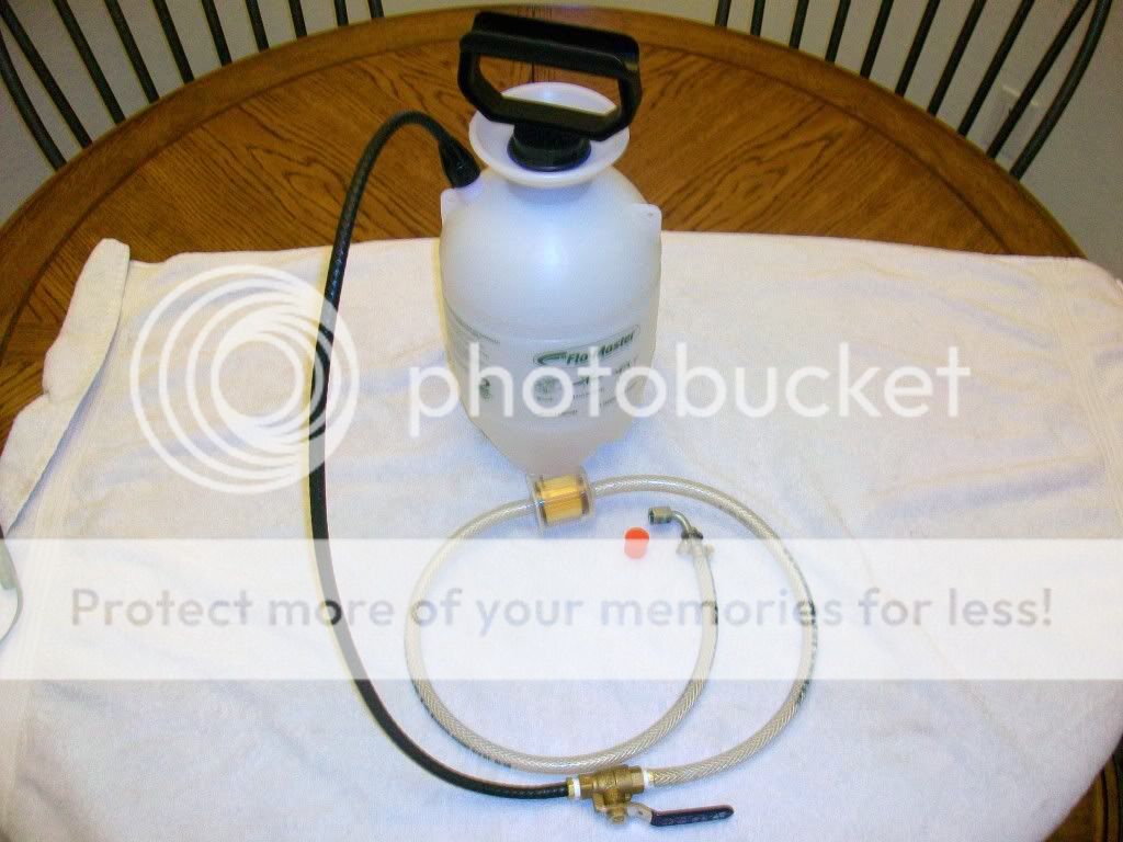
I have assembled an inexpensive pressure tank to prelube this engine - same as everyone else. Insecticide sprayer was purchased from Home Depot along with some misc. fittings & hose. One exception is that I have added an inline filter.
When pressurizing the lubrication systems on our engines via the oil pressure sensor port (because it's convenient) everyone needs to remember that this location is after the oil filter. Therefore if there are any contaminants in our pressure bleeding apparatus they are introduced directly into the engine.
The filter I chose was a NAPA part# 3001. It has a 1/4" inlet & outlet and filter media is 12 microns. Our OEM oil filter is 19 microns. This should keep any contaminants from inadvertently entering the engine and should keep our oil ISO at about a 15/13 which is very clean.
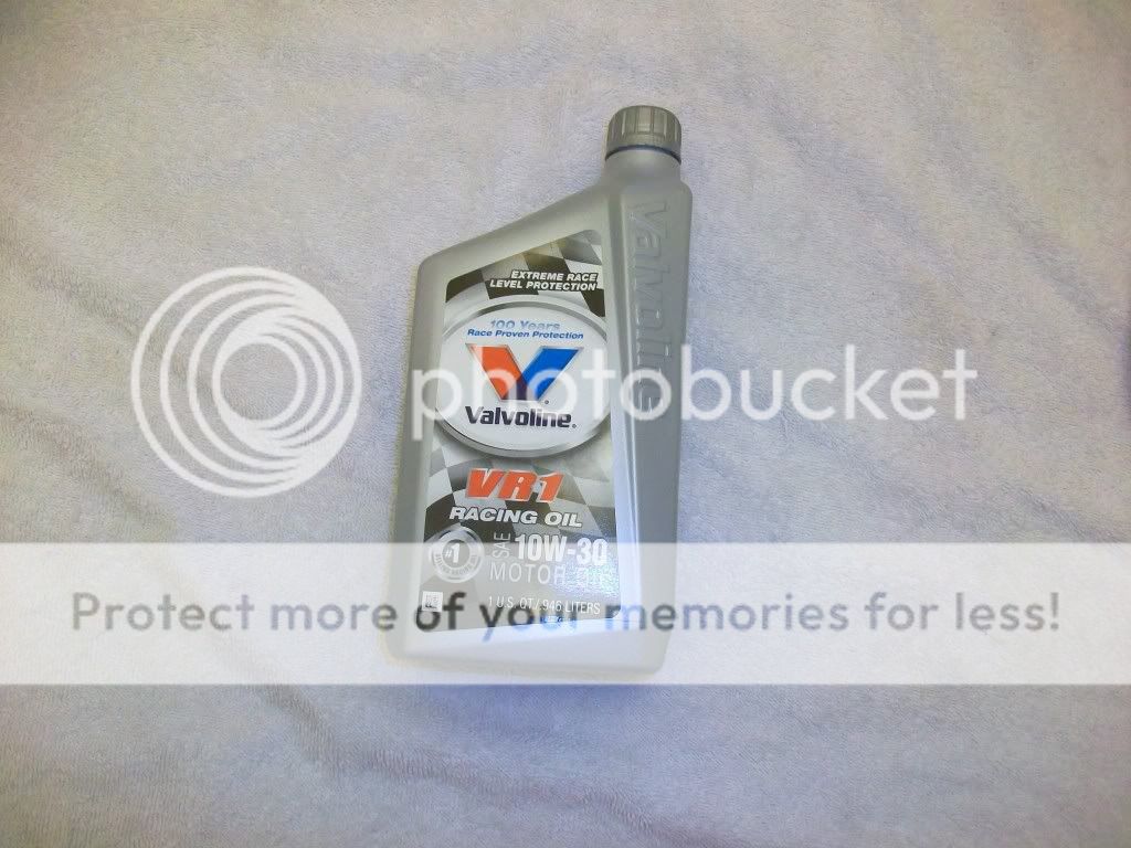
The oil I have chosen to prelube/break in this engine is Valvoline VR1 10W-30 Racing Oil - non synthetic. This oil has a high level of zinc/phosphorus to reduce initial break in wear.
When pressurizing the lubrication systems on our engines via the oil pressure sensor port (because it's convenient) everyone needs to remember that this location is after the oil filter. Therefore if there are any contaminants in our pressure bleeding apparatus they are introduced directly into the engine.
The filter I chose was a NAPA part# 3001. It has a 1/4" inlet & outlet and filter media is 12 microns. Our OEM oil filter is 19 microns. This should keep any contaminants from inadvertently entering the engine and should keep our oil ISO at about a 15/13 which is very clean.
The oil I have chosen to prelube/break in this engine is Valvoline VR1 10W-30 Racing Oil - non synthetic. This oil has a high level of zinc/phosphorus to reduce initial break in wear.
NastyStang113
Made in U.S.A.
Just curious, what oil do you plan on running in it? 10w40?
tmcolegr
It's All About the Build
Just curious, what oil do you plan on running in it? 10w40?
The oil I have chosen to prelube/break in this engine is Valvoline VR1 10W-30 Racing Oil - non synthetic. This oil has a high level of zinc/phosphorus to reduce initial break in wear.
10W-30
NastyStang113
Made in U.S.A.
I was asking about after break in.
tmcolegr
It's All About the Build
10W-30
NastyStang113
Made in U.S.A.
Gotcha, threw me because you said pre-lube and break in.. Do you have any idea what kind of bearing tolerances are needed for each weight oil?
Similar threads
- Replies
- 0
- Views
- 271
- Replies
- 3
- Views
- 904
Support us!
Support Us - Become A Supporting Member Today!
Click Here For Details
Sponsor Links