1st Gen Coyote Knock Sensor to Cylinder Assignment

GlassTop09

Senior Member
Joined
May 24, 2019
Posts
1,145
Reaction score
526
Location
Farmington, NM
FYI.......................

I was killing some time today so I pulled up a 1st Gen Copperhead PCM tune file (11-14 MY Coyote engines) in HPTuners Editor software then set up a '05 GT SO PCM tune file in Compare & looked at the Knock Sensor section & found that Ford used the exact same KS mic to cyl assignment mapping for both the 05-10 4.6L 3V & 11-14 5.0L Coyote engines that I found an error in this mapping that was causing some false cyl knock\aggravated cyl knock levels in certain cyls according to engine firing order sequencing during self-tuning on my '09 GT which was using this exact same KS mic to cylinder assignment pattern that I resolved on my '09 GT by reassigning #2 cyl from #0KS mic to #1KS mic & #6 cyl from #1KS mic to #0KS mic as these 2 cyls were the ones assigned out of firing order "phasing" for the KS mics causing the following cyls from the 1st cyl assigned in firing order to receive elevated KS mic voltage signal output generation due to successive cyls firing in the 90* firing sequence using the same KS mic as the 1st cyl, instead of using the opposite KS mic from the leading cyl.

I drew these pictures to represent this KS mic to cyl assignment pattern as found in the Copperhead tune file I was looking at then w\ the corrected KS mic to cyl assignment pattern that will correct the base KS mic voltage output signal "phasing" to each leading\following cyl according to engine firing order sequence when engine is running when using all Ford tuned OEM per cyl knock sensitivity threshold map settings by reassigning the exact same 2 cyls in the exact same manner as the 2 engines are using the exact same engine KS mic to cyl assignment map settings:
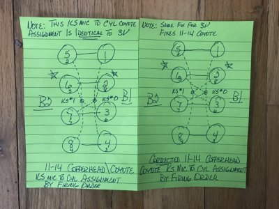
11-14 Copperhead Coyote Knock Sensor to Cylinder Assignments.JPG
The 11-14 Coyote's firing order sequence is denoted by the small number located at bottom of each cylinder. Just follow them in numerical order to follow actual engine firing order sequence to see what I'm explaining here.

Something to consider for all my 1st Gen Coyote brethren if your engine is suffering from crazy cyl knock issues\patterns. Don't take my word on this........test this out for yourselves.

I believe this KS assignment error (that it appears that Ford never identified\caught since 05.........) has a part to play as to why Ford, starting w\ the '15 & up MY's, went to a 4 KS mic arrangement (2 KS mics per bank of cyls) on all Coyote\Coyote variant engines.

07-10 Ford Mod Motor GT500 engines using the 5.4L SC V8 has this exact same KS mic to cyl assignment error in its tune files as well................
 

crjackson

Member
Joined
Nov 28, 2015
Posts
609
Reaction score
308
Location
Midgard
That is interesting indeed. Even though this technology is way over my head, you did spark a question or two…

Did the Gen1’s have only 2 KS’s total, or are you only mentioning the 2 that are out of phase? Showing my ignorance here, but it sounds like the former.

Also, aside from data readouts, what real world symptoms arise as a result of being phased incorrectly?
 

Laga

Senior Member
Joined
Aug 10, 2019
Posts
999
Reaction score
521
Location
Chicago
That is interesting indeed. Even though this technology is way over my head, you did spark a question or two…

Did the Gen1’s have only 2 KS’s total, or are you only mentioning the 2 that are out of phase? Showing my ignorance here, but it sounds like the former.

Also, aside from data readouts, what real world symptoms arise as a result of being phased incorrectly?
There are 2.
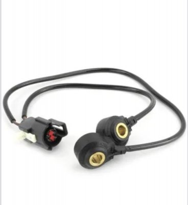
These are the KSs for Gen1. They sit on pedestal like structures on the sides of the valley underneath the the intake manifold at the center of the engine. They are supposed to be torqued down to 15 ft/lbs. I had my 05 engine rebuilt last summer and they torqued them down to 25 ft/lbs, and that lead to a lot of false knock problems for Lito try to tune the rebuild. The over torqued sensors were picking up more vibrations than normal. After I found the problem, it made tuning much easier. 6C966496-9353-4EB6-B0CE-13EC58E365F7.jpeg
 

crjackson

Member
Joined
Nov 28, 2015
Posts
609
Reaction score
308
Location
Midgard
Thanks for the info. They should be color coded or made in such a way so as not to reverse them. It looks like it would be easy to install incorrectly.
 

Laga

Senior Member
Joined
Aug 10, 2019
Posts
999
Reaction score
521
Location
Chicago
Thanks for the info. They should be color coded or made in such a way so as not to reverse them. It looks like it would be easy to install incorrectly.
One wire is longer than the other. They plug into a connector at the back of the engine on the passenger side. This makes it obvious because the driver side pedestal is further away.
 

Pentalab

forum member
Joined
Mar 5, 2013
Posts
5,216
Reaction score
1,104
FYI.......................

I was killing some time today so I pulled up a 1st Gen Copperhead PCM tune file (11-14 MY Coyote engines) in HPTuners Editor software then set up a '05 GT SO PCM tune file in Compare & looked at the Knock Sensor section & found that Ford used the exact same KS mic to cyl assignment mapping for both the 05-10 4.6L 3V & 11-14 5.0L Coyote engines that I found an error in this mapping that was causing some false cyl knock\aggravated cyl knock levels in certain cyls according to engine firing order sequencing during self-tuning on my '09 GT which was using this exact same KS mic to cylinder assignment pattern that I resolved on my '09 GT by reassigning #2 cyl from #0KS mic to #1KS mic & #6 cyl from #1KS mic to #0KS mic as these 2 cyls were the ones assigned out of firing order "phasing" for the KS mics causing the following cyls from the 1st cyl assigned in firing order to receive elevated KS mic voltage signal output generation due to successive cyls firing in the 90* firing sequence using the same KS mic as the 1st cyl, instead of using the opposite KS mic from the leading cyl.

I drew these pictures to represent this KS mic to cyl assignment pattern as found in the Copperhead tune file I was looking at then w\ the corrected KS mic to cyl assignment pattern that will correct the base KS mic voltage output signal "phasing" to each leading\following cyl according to engine firing order sequence when engine is running when using all Ford tuned OEM per cyl knock sensitivity threshold map settings by reassigning the exact same 2 cyls in the exact same manner as the 2 engines are using the exact same engine KS mic to cyl assignment map settings:
View attachment 85992
The 11-14 Coyote's firing order sequence is denoted by the small number located at bottom of each cylinder. Just follow them in numerical order to follow actual engine firing order sequence to see what I'm explaining here.

Something to consider for all my 1st Gen Coyote brethren if your engine is suffering from crazy cyl knock issues\patterns. Don't take my word on this........test this out for yourselves.

I believe this KS assignment error (that it appears that Ford never identified\caught since 05.........) has a part to play as to why Ford, starting w\ the '15 & up MY's, went to a 4 KS mic arrangement (2 KS mics per bank of cyls) on all Coyote\Coyote variant engines.

07-10 Ford Mod Motor GT500 engines using the 5.4L SC V8 has this exact same KS mic to cyl assignment error in its tune files as well................
You should pass this info on to LITO.
 

GlassTop09

Senior Member
Joined
May 24, 2019
Posts
1,145
Reaction score
526
Location
Farmington, NM
That is interesting indeed. Even though this technology is way over my head, you did spark a question or two…

Did the Gen1’s have only 2 KS’s total, or are you only mentioning the 2 that are out of phase? Showing my ignorance here, but it sounds like the former.

Also, aside from data readouts, what real world symptoms arise as a result of being phased incorrectly?
Yes, all Gen 1 Coyote blocks have 2 KS mics in same locations\arrangement as all 05-10 3V blocks do.......thus Ford carried over all the same calibration coding for the per cyl knock detection routines from the SO PCM calibration to the 1st Gen Coyote\Copperhead PCM platform.
Remember, there's a fair amount of similarity between these 2 engine classes when you look at the block design\rotating assemblies between the 2 thus some parts can be swapped between the 2 (like the block itself...ie, a lot of folks use a Boss block as a base to up 3V displacement, or the connectig rods....ie, some folks use Boss con rods to "forge" a 4.6L rotatig assembly, etc) thus some SO PCM calibration coding can also be substituted for use (classic computer programming technique to save time by editing in sections of already compiled\vetted code that fits the designed intention of a newer platform instead of rewriting the same coding over again......called redundancy. There's a lot more SO PCM calibration coding that was used to write the 1st Gen Copperhead PC calibrations........).

The base calibration knock detection routines were written to detect cyl knock on a per cyl basis......thus when a cyl fires (PCM is using crank angle to determine engine firing\piston position during the EOC\BOP stroke thus is unique to every cyl) the PCM looks at both KS mics (the assigned KS mic to cyl is primary thus the unassigned becomes secondary) as both will respond to any engine noise generated but PCM only concentrates on KS mic signal voltage outputs generated within each cyl's CA firing window (from when the plugs are fired to approx 40* into the power stroke--area where cyl pressures will be their highest after plug is fired thus prone to detonation......optimum for cyl pressure is 17* ATDC or 163* CA, this the CA when the piston starts moving down from top dwell position during power stroke) after TDC. This area after TDC on the power stroke side is where any KS mic that is assigned to successive lead\trail cyls in firing order sequence can get skewed\elevated voltage output signaling thus can artificially drive the trailing cyl noise above its knock sensitivity threshold map settings causing.......elevated\false cyl knock. This is minimized by ensuring that every cyl in the firing order sequence is assigned to use the opposite KS mic, thus maintains this unique firing cyl CA area noise "phasing" thus aids PCM in interpretation of its noise during the firing cycle to either ignore all "white" noise that is out of this pattern then be better able to interpret any noise that is generated within each cyl's firing window for the telltale noise spike from detonation (the 2 flame fronts colliding from the spontaneous flame front generated from the heat\pressure created after the initial flame front created from the plug igniting) in each cyl's CA detection window.

This is where the VCT cam retarding can set this up\aggravate this when the cams EVO are retarded to\past 73* BBDC (lines up w\ the 17* ATDC CA point as this will tie the lead\trail cyls together on the 90* crankshaft throws applying their force together thus can transfer their noise frequencies to each other as well thru the crankshaft---I posted a drawing of this in another thread. The cyls in the center of the crankshaft are the most vulnerable to this occurring due to proximity....is also where the KS mic misassignment is located).

When you map all this out, it appears that Ford's intention was for this alternating KS mic assignment to cyl by firing order......you can see it on every cyl.......except #2cyl & #6cyl......these 2 cyls are on the same crankshaft journal thus the KS mic assignment is correct........for them, but it breaks the pattern for the others. By simply reassigning these 2 cyls to the opposite KS mic they were originally assigned to still preserves their integrity.....but this also fixes this for the rest of the cyls in succession at the same time.

Thus, IMHO, this had to be a mistake on Ford's part, but for some reason Ford chose to ignore it\overlook it thus this became the std pattern across the board. This issue is also causing Global Mode knock control to be off as well, but due to the associated coding this mode uses, it is avg'ing all this out to assign any per cyl knock to all 8 cyls thus will cut spark advance timing to all 8 cyls.......instead of to the offending cyl(s) only. So Global Mode seems to be more "accurate" than Per Cyl Mode at 1st glance......but the base code knock detection routines are on a per cyl basis for BOTH modes of knock detection.......which IMHO makes absolutely no sense to do\use when it is a known fact that engine HP\TQ output will be overall less affected using Per Cyl Mode knock control vs Global Mode knock control while at the same time maintaining engine safety.

But this KS mic to cyl assignment error will make Per Cyl Mode to look very out of sorts vs Global Mode on 1st impressions thus IMHO some have misinterpreted this to be due to the base coding routines used w\ Per Cyl Mode......when in reality it is simply a KS mic to cyl assignment mistake between #2 & #6 cyls that is the cause.......Global Mode is actually masking this mistake.

Hope this helps.
 
Last edited:

GlassTop09

Senior Member
Joined
May 24, 2019
Posts
1,145
Reaction score
526
Location
Farmington, NM
You should pass this info on to LITO.
If you want to see\know just how much this site's postings get flagged in online searches go on Google or Bing & type some of these topics in their search engines....................

I'll guarantee that a fair amount of folks have already seen these postings that never come into this site........

Ask me how I know this......................
 

crjackson

Member
Joined
Nov 28, 2015
Posts
609
Reaction score
308
Location
Midgard
Hope this helps.
Thanks, prolly over my head, but I’ll look again later after I sleep, and my eyes can focus better.

Next Day Edit:
Okay, I was right. It’s over my head. I understood a good bit of it though. Thanks for the detailed response. As I’m only a guppy, you may have just, over-fed this fish :)
 
Last edited:

Pentalab

forum member
Joined
Mar 5, 2013
Posts
5,216
Reaction score
1,104
Yes, all Gen 1 Coyote blocks have 2 KS mics in same locations\arrangement as all 05-10 3V blocks do.......thus Ford carried over all the same calibration coding for the per cyl knock detection routines from the SO PCM calibration to the 1st Gen Coyote\Copperhead PCM platform.
Remember, there's a fair amount of similarity between these 2 engine classes when you look at the block design\rotating assemblies between the 2 thus some parts can be swapped between the 2 (like the block itself...ie, a lot of folks use a Boss block as a base to up 3V displacement, or the connectig rods....ie, some folks use Boss con rods to "forge" a 4.6L rotatig assembly, etc) thus some SO PCM calibration coding can also be substituted for use (classic computer programming technique to save time by editing in sections of already compiled\vetted code that fits the designed intention of a newer platform instead of rewriting the same coding over again......called redundancy. There's a lot more SO PCM calibration coding that was used to write the 1st Gen Copperhead PC calibrations........).

The base calibration knock detection routines were written to detect cyl knock on a per cyl basis......thus when a cyl fires (PCM is using crank angle to determine engine firing\piston position during the EOC\BOP stroke thus is unique to every cyl) the PCM looks at both KS mics (the assigned KS mic to cyl is primary thus the unassigned becomes secondary) as both will respond to any engine noise generated but PCM only concentrates on KS mic signal voltage outputs generated within each cyl's CA firing window (from when the plugs are fired to approx 40* into the power stroke--area where cyl pressures will be their highest after plug is fired thus prone to detonation......optimum for cyl pressure is 17* ATDC or 163* CA, this the CA when the piston starts moving down from top dwell position during power stroke) after TDC. This area after TDC on the power stroke side is where any KS mic that is assigned to successive lead\trail cyls in firing order sequence can get skewed\elevated voltage output signaling thus can artificially drive the trailing cyl noise above its knock sensitivity threshold map settings causing.......elevated\false cyl knock. This is minimized by ensuring that every cyl in the firing order sequence is assigned to use the opposite KS mic, thus maintains this unique firing cyl CA area noise "phasing" thus aids PCM in interpretation of its noise during the firing cycle to either ignore all "white" noise that is out of this pattern then be better able to interpret any noise that is generated within each cyl's firing window for the telltale noise spike from detonation (the 2 flame fronts colliding from the spontaneous flame front generated from the heat\pressure created after the initial flame front created from the plug igniting) in each cyl's CA detection window.

This is where the VCT cam retarding can set this up\aggravate this when the cams EVO are retarded to\past 73* BBDC (lines up w\ the 17* ATDC CA point as this will tie the lead\trail cyls together on the 90* crankshaft throws applying their force together thus can transfer their noise frequencies to each other as well thru the crankshaft---I posted a drawing of this in another thread. The cyls in the center of the crankshaft are the most vulnerable to this occurring due to proximity....is also where the KS mic misassignment is located).

When you map all this out, it appears that Ford's intention was for this alternating KS mic assignment to cyl by firing order......you can see it on every cyl.......except #2cyl & #6cyl......these 2 cyls are on the same crankshaft journal thus the KS mic assignment is correct........for them, but it breaks the pattern for the others. By simply reassigning these 2 cyls to the opposite KS mic they were originally assigned to still preserves their integrity.....but this also fixes this for the rest of the cyls in succession at the same time.

Thus, IMHO, this had to be a mistake on Ford's part, but for some reason Ford chose to ignore it\overlook it thus this became the std pattern across the board. This issue is also causing Global Mode knock control to be off as well, but due to the associated coding this mode uses, it is avg'ing all this out to assign any per cyl knock to all 8 cyls thus will cut spark advance timing to all 8 cyls.......instead of to the offending cyl(s) only. So Global Mode seems to be more "accurate" than Per Cyl Mode at 1st glance......but the base code knock detection routines are on a per cyl basis for BOTH modes of knock detection.......which IMHO makes absolutely no sense to do\use when it is a known fact that engine HP\TQ output will be overall less affected using Per Cyl Mode knock control vs Global Mode knock control while at the same time maintaining engine safety.

But this KS mic to cyl assignment error will make Per Cyl Mode to look very out of sorts vs Global Mode on 1st impressions thus IMHO some have misinterpreted this to be due to the base coding routines used w\ Per Cyl Mode......when in reality it is simply a KS mic to cyl assignment mistake between #2 & #6 cyls that is the cause.......Global Mode is actually masking this mistake.

Hope this helps.

Are you saying that this can all be fixed via just software ??
 

crjackson

Member
Joined
Nov 28, 2015
Posts
609
Reaction score
308
Location
Midgard
Let me ask another stupid question…

Do you think that any of the big-name ‘Yote tuners (LUND, AED,VMP, Decipha), are aware of this and are skilled enough to really dive-in and actually perfect, every little detail in their custom Dyno tune on a per-car basis? It would probably be prohibitively expensive, but I wonder if the needed skills/understanding are even there.
 
Last edited:

GlassTop09

Senior Member
Joined
May 24, 2019
Posts
1,145
Reaction score
526
Location
Farmington, NM
Let me ask another stupid question…

Do you think that any of the big-name ‘Yote tuners (LUND, AED,VMP, Decipha), are aware of this and are skilled enough to really dive-in and actually perfect, every little detail in their custom Dyno tune on a per-car basis? It would probably be prohibitively expensive, but I wonder if the needed skills/understanding are even there.
They maybe fully aware of this & just don't make their knowledge of this available to the public at large for competitive business purposes as they ARE in the business of making money thru providing tuning services to the general public as well as professional racers\racing teams...........they may not be aware\don't care either...........thus we can only either IMPLY that they know or they don't as only THEY can answer that question accurately.......for themselves.

Outside of this it's just pure speculation on anyone else's part.........

They may also have these tools in hand:
PLEX KNOCK MONITOR V3 | Tune Like A Pro. Never Miss Knock Again. (plex-tuning.com)
Knock Monitor Pro – TN Performance / Tuner Nerd
These are a couple of the most popular IC engine knock detection tools out there being used as an outside alternative system to check the OEM knock sensor\PCM knock detection coding operations to determine real cyl knock from false cyl knock & can do it on a per cyl basis as well as a global basis---just like the OEM system is coded to do.......I'll bet the farm that all those big tuning names you've mentioned have such a system in hand (if they're as good as they say they are, they're also smart enough to have this type of equipment in hand) so w\ these systems the OEM PCM calibration knock control system integrity isn't as critical as only the OEM per cyl knock sensitivity threshold mapping needs to be adjusted to fit what the external knock detection system has determined what's real from what's false......which is just fine for their purposes........as long as the customer stays w\ them doing all subsequent tuning since they KNOW what was initially done in the tune file........so unless they actually TELL the customer all that THEY did in the tune file to tune your car after finishing it........the customer doesn't know either........thus the customer is TRUSTING them to do the tuning properly as the customer believes it should be, since the customer is PAYING for the service.

In order to use this external equipment, a tuner has to believe\prove that the OEM engineers, computer programmers have to be somewhat incompetent w\ their in house PCM calibration knock control systems coding process thus is fundamentally flawed to just blindly use an outside system as these systems aren't exactly cheap (especially the Plex as this is considered the best of the best out there---the price reflects it as well).........or IMHO this is more a business-driven decision to make more money by using an external system instead of investing a lot of time TS'ing\resolving an OEM calibration subsystem that should've already been fully fleshed out by the OEM in house QA\QC......... GM OEM calibrations knock control systems are known for excessive false knock detection\generation as well.......

I'm actually considering getting the Tuner Nerd Pro Elite+ system myself just to have on hand, due to seeing several good reviews on it from a couple of respected tuners (Andre Simon @ HPA & Joe Simpson @ Tempest Racing) & its cost is in the range of what I would pay for this type of system to use for my own personal use.

The only reason why I posted this in the 1st place is due to my own work on my own car in which I used my background knowledge of basic computer programming\operations & looking at the tune files setup\settings to get an understanding of the underlying PCM code logic process\operation thus figure all this out w\ some help from a well-known, respected tuner (Jeffery Evans @ EPA is well known back East......I've also communicated w\ long tenured professional tuners on HPTuners site who were also subscribed on Evans Performance Academy site's forums as well........to this date I haven't had either of these tuners\other tuners on Jeff's forums tell me that what I've found & posted on Jeff's forums concerning all this was incorrect\wrong.......the same stuff I've posted in this site's forums---with the same pictures\drawings.....just so all here knows) to provide info that could be of some use\help to other tuners\owners of 1st Gen 11-14 Coyote engines so that they are aware of the Copperhead PCM calibrations knock sensors KS mic to cyl assignment mapping having the exact same KS mic to cyl assignment issues as I've found\tested\corrected\verified in my '09 GT's SO PCM calibration that I've also verified exists in all 05-10 OEM GT 07-10 OEM GT500 SO PCM calibrations that I have access to was causing the Per Cyl Mode knock control to put out bad info under high engine loading conditions only using the OEM Ford-tuned per cyl knock sensitivity threshold map settings (as would be the same case for the Global Mode knock control since they both use the exact same base PCM calibration per cyl knock detection coding routines----kind of a false statement to say that in 1 mode the base calibration knock detection routines are flawed but in the other mode the same base routines are fine......a LOT of tuners will tell you to not use Per Cyl Mode in favor of Global Mode that Ford chose to use----computer programming doesn't work that way thus something else--like a setting mistake entered into the code logic process that 1 mode is coded to mask over it vs the other 1--is causing this distinction between the 2 modes---not an issue in the base PCM calibration knock detection coding routines per se & also verified thru using HPTuners Editor Compare feature that the 1st Gen Copperhead OEM PCM calibrations are using the exact same knock control coding routines as the SO PCM calibrations......with the exact same setting mistake made that when I applied the exact same correction to it that I applied to my SO PCM tune file.....even though the engine firing order sequencing is different between the 2 engines.....the correction pattern came out exactly the same for both engine's firing order sequencing......further indicating IMHO that the original OEM KS mic to cyl assignment for #2\#6 cyls was a simple mistake which is easily corrected by just swapping them to the opposite KS mic from the 1 they were originally assigned to in the tune file which now corrects this base per cyl KS mic noise output detection pattern across the entire engine firing order sequencing as demonstrated in the 2 drawings I provided thus should also improve PCM interpretation between real & false cyl knock using the base OEM Ford-tuned per cyl knock sensitivity threshold mapping untouched......for both 3V's & 1st Gen Coyotes.......under both Per Cyl Mode & Global Mode knock control routines in their respective calibrations (1st Gen Coyotes Copperhead PCM calibrations also showed to be OEM set to use Global Mode knock control instead of Per Cyl Mode knock control......just like the 3V's were......IMHO this decision was made w\ the 1st Gen Coyotes due to the same "problem" perceived on the 3V's).

I've also made the statement in my original posting for anyone to not take my word for it & to test this out for yourselves to either prove what I've posted wrong or verify what I've already verified for myself to be correct.

Choice is up to the reader.
 
Last edited:

Juice

forum member
Joined
Aug 24, 2017
Posts
4,622
Reaction score
1,905
Having trouble digesting this.
Why would Ford not assign the knock sensor on bank 1 to cylinders on bank 1, and same with bank 2 sensor/cylinders?

Looking at the coyote calibration in SCT, 2 cylinders from each bank are assigned to each KS mic by default. The potential issue I see is, KS 0 has three firing events in a row for 8,6,3 cylinders. Swapping 6&2, will reduce this to two consecutive events on one KS. So if KS assignment is not by bank, it would make more sense to alternate knock sensors in the firing order.

Guess I can incorporate this into my next tune revision and test. (still chasing why the O2 monitors are not completing) Not sure if I can log individual cylinders in LiveLink, but if this works, WOT timing should increase a degree or two.

Coyote firing order:1-5-4-8-6-3-7-2
Stock KS assignment:0-1-1-0-0-0-1-1

Glasstop's reassignment:
Cyl#:1-5-4-8-6-3-7-2
KS#:0-1-1-0-1-0-1-0

I should also test:
1-5-4-8-6-3-7-2
0-1-0-1-0-1-0-1
 
Last edited:

Support us!

Support Us - Become A Supporting Member Today!

Click Here For Details

Sponsor Links

Banner image
Back
Top