Redrocket06
forum member
Upgrading the 12V feed from the BEC to the coils and the grounds from the coils to the PCM. Some have done this to combat spark blowout. This has been talked about but I wanted to put up some pics to help with clarification. Wire diagram: http://iihs.net/fsm/?dir=40&viewfile=Electronic Engine Controls - 4.6L.pdf
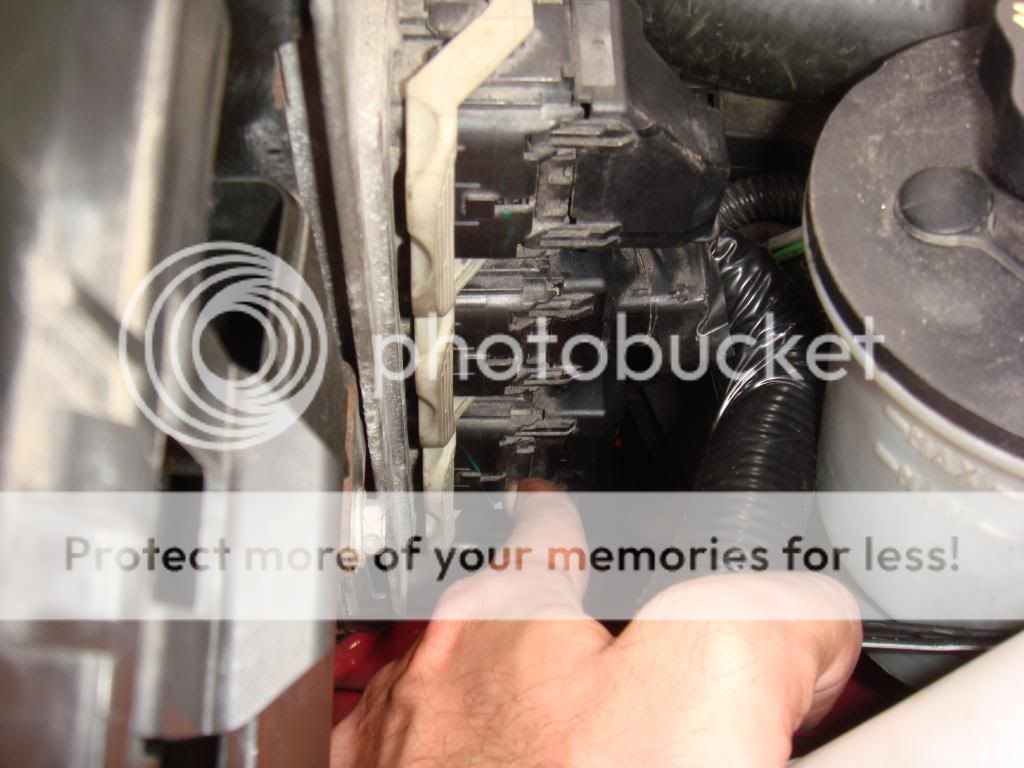
On the PCM the bottom connector is where all the coil grounds return to.
I don't have pics of the botton PCM connector with the loom removed. But my wire colors matched the colors indicated in the diagram link posted up top:
Cylinder Color Stripe
1 LT Green White
2 pink white
3 white pink
4 DK green violet
5 LT green yellow
6 orange yellow
7 pink LT Blue
8 white red
You will cut these wires leaving enough to strip and solder larger awg grounding wire from the coils (I used 12awg). It is important to match each wire to the proper cylinder, if you fail your car will not run.
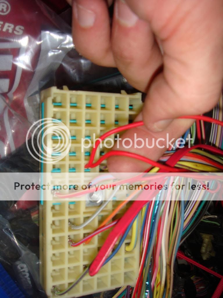
Fuse box/BEC removed and upside down, 12V feed is from the green section (closest to the battery):

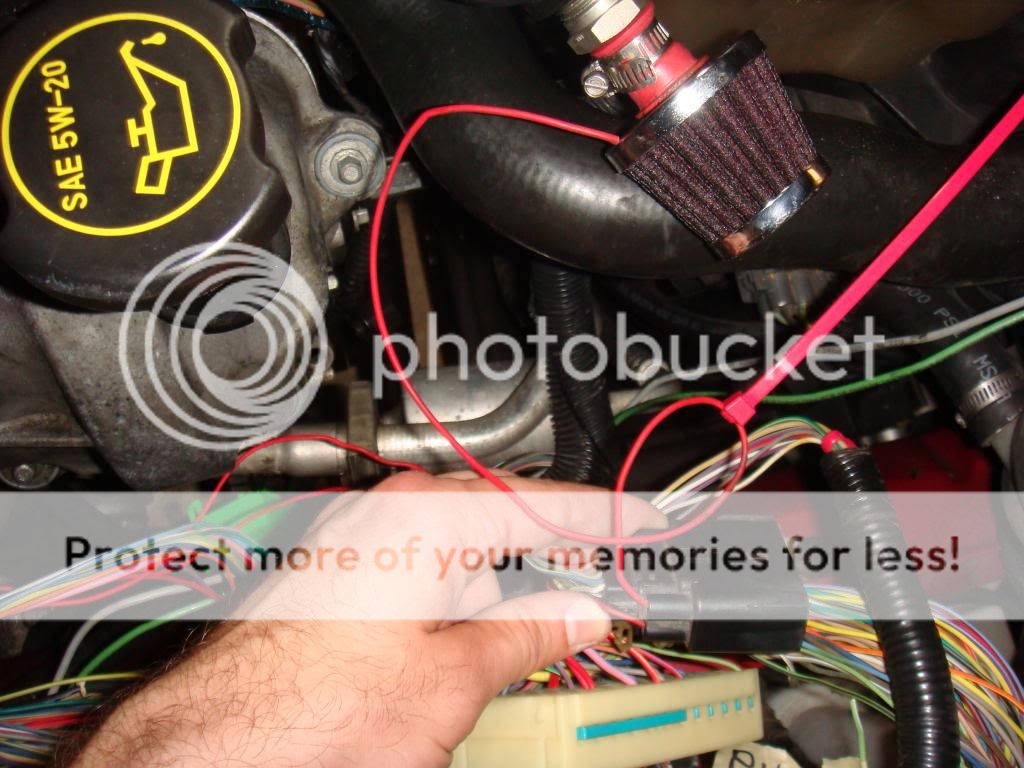
Green section disassembled and you will need these two red wires that are sharing a square. Check from here to the coil connector with a multimeter before cutting (fuel injector 12V feed is on the same block and have 2 red wires sharing a square too). Cut them leaving enough to strip and solder larger awg to them. I cut the wire leaving about 4-5 inches and soldered larger driverside wire to one and larger passengerside wire to the other. This is 12V always hot, so matching which goes to what side is not important here. I used 10awg wire.:
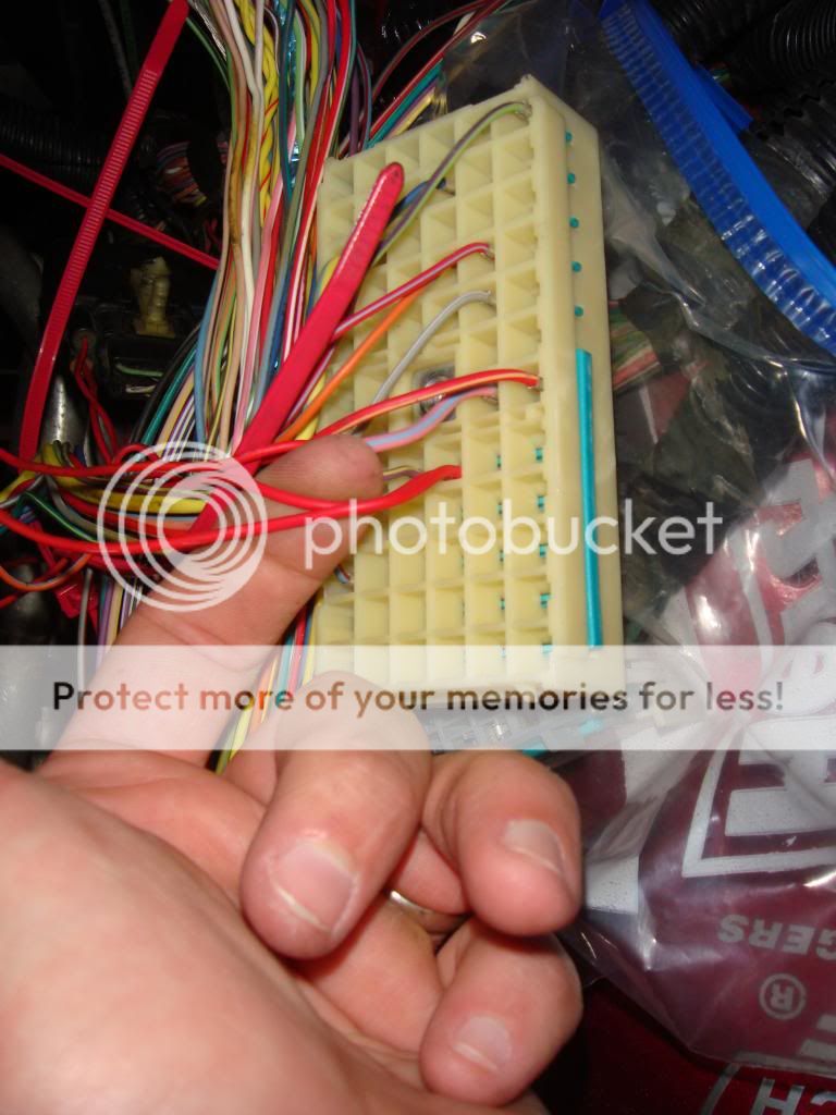
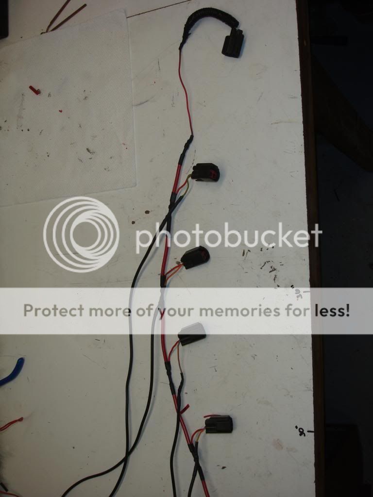
After cutting coil connectors off and making harness. I used 2 10awg wires (one for each bank) for 12V feed from the BEC, and a 12awg for coil grounding back to the PCM (each coil has to have its own ground back to the PCM). I made all the wire I used the same length to equalize resistance across the circuit. About 6ft each (made hiding wire interesting in the end). solder all connections with rosin core solder and heat shrink wrap. I also kept the ignition transformer capacitor (some I have read deleted it).

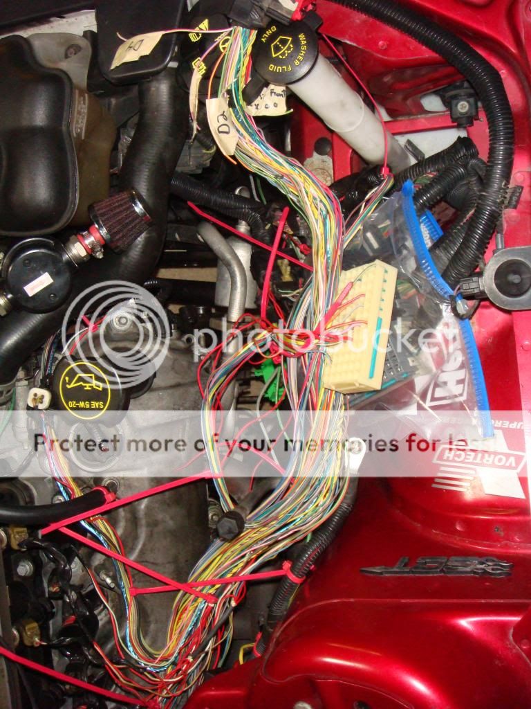
After tracing out the 12V feed I couldn't figure out where this wire went (one with a red zip tie going into connector C110), after spending many hours looking in wire diagrams and connector pinouts and some help on here I did not include it in my new harness. No ill effects found as of yet. Thread asking for help/info:http://www.s197forum.com/forum/showthread.php?t=107044

On the PCM the bottom connector is where all the coil grounds return to.
I don't have pics of the botton PCM connector with the loom removed. But my wire colors matched the colors indicated in the diagram link posted up top:
Cylinder Color Stripe
1 LT Green White
2 pink white
3 white pink
4 DK green violet
5 LT green yellow
6 orange yellow
7 pink LT Blue
8 white red
You will cut these wires leaving enough to strip and solder larger awg grounding wire from the coils (I used 12awg). It is important to match each wire to the proper cylinder, if you fail your car will not run.

Fuse box/BEC removed and upside down, 12V feed is from the green section (closest to the battery):

Green section disassembled and you will need these two red wires that are sharing a square. Check from here to the coil connector with a multimeter before cutting (fuel injector 12V feed is on the same block and have 2 red wires sharing a square too). Cut them leaving enough to strip and solder larger awg to them. I cut the wire leaving about 4-5 inches and soldered larger driverside wire to one and larger passengerside wire to the other. This is 12V always hot, so matching which goes to what side is not important here. I used 10awg wire.:


After cutting coil connectors off and making harness. I used 2 10awg wires (one for each bank) for 12V feed from the BEC, and a 12awg for coil grounding back to the PCM (each coil has to have its own ground back to the PCM). I made all the wire I used the same length to equalize resistance across the circuit. About 6ft each (made hiding wire interesting in the end). solder all connections with rosin core solder and heat shrink wrap. I also kept the ignition transformer capacitor (some I have read deleted it).


After tracing out the 12V feed I couldn't figure out where this wire went (one with a red zip tie going into connector C110), after spending many hours looking in wire diagrams and connector pinouts and some help on here I did not include it in my new harness. No ill effects found as of yet. Thread asking for help/info:http://www.s197forum.com/forum/showthread.php?t=107044