Fuse box fan relay terminal burnt

joshuamedina653

Junior Member
Joined
Jul 26, 2018
Posts
25
Reaction score
0
So one day it was super hot and i was driving all day then all of a sudden my car overheated, i thought maybe it was my thermostat, so i changed that out drove the car around after replacing the thermostat car overheated again, and noticed the fan shut off when the car overheated, so i came too the conclusion maybe it was something with the relays switched out the relays, for new ones car once again over heated and swapped the fan out for a new one also. Decided to open the fuse boz and found a burnt terminal under the fuse box, so i ended up going to the junk yard getting a whole new piece of wire and terminal, replaced it put it in and, test drove the car today and seems like the fan it still coming on at operating temp at high speed, the relay gets really hot, im sure that’s what caused it too short out the first time. Could it be the thermostat that has changed at what temperature the fan operate? Car is tuned also!


Sent from my iPhone using Tapatalk
 

MrBhp

Senior Member
Joined
Sep 12, 2013
Posts
1,257
Reaction score
1,038
It's a problem many have had. The circuit is barely big enough when it's new. As the fan gets older it draws more current, the power distribution box will start to fry at the relay connection, which causes more resistance, which causes more heat, etc. Best thing is to move the relay outside the box. You'll need to separate the box to get the wiring figured out,IIRC. You may end up replacing the fan as well. But the relay relocation is the first thing to do.
 

joshuamedina653

Junior Member
Joined
Jul 26, 2018
Posts
25
Reaction score
0
It's a problem many have had. The circuit is barely big enough when it's new. As the fan gets older it draws more current, the power distribution box will start to fry at the relay connection, which causes more resistance, which causes more heat, etc. Best thing is to move the relay outside the box. You'll need to separate the box to get the wiring figured out,IIRC. You may end up replacing the fan as well. But the relay relocation is the first thing to do.

So i may have too relocate both fan relays? Relocating them would fix the issue i assume, i replaced the fan also, already. I read another forum. But it was still confusing too me, I’ve never dealt with an electrical problem like this,


Sent from my iPhone using Tapatalk
 

MrBhp

Senior Member
Joined
Sep 12, 2013
Posts
1,257
Reaction score
1,038
I think it's just the high speed relay. The burnt end you found was on the high speed relay, correct? I'll look at mine later. I'm fairly certain I have just one relay and one fuse attached to the outside of the box.
 

joshuamedina653

Junior Member
Joined
Jul 26, 2018
Posts
25
Reaction score
0
I think it's just the high speed relay. The burnt end you found was on the high speed relay, correct? I'll look at mine later. I'm fairly certain I have just one relay and one fuse attached to the outside of the box.

Sounds good, and yes the burnt one was from the high speed relay i believe !


Sent from my iPhone using Tapatalk
 

DieHarder

Senior Member
Joined
Nov 9, 2019
Posts
1,468
Reaction score
758
The wiring in our cars is going on ~15+ yrs now. The problem is resistance/current. As stated the circuit was barely adequately sized when new. Over time naturally occurring oxidation and corrosion where metal surfaces meet increases resistance within the circuit. Since the voltage/pressure is constant the current must increase to compensate for the change in resistance which results in increased heat and burned wiring.

You can deal with this problem in a couple of ways. 1) Externalize relays/ route new lines as described above. If you do highly suggest increasing the size of the wiring by a gauge or two and use high quality stranded copper wiring (no aluminum or copper coated aluminum). Or... 2) Parallel/sister the existing wiring with wires of the same size/grade. This has worked well for me in a few of instances and does not require externalizing the relays. You will however have to ID/trace cabling from point to point which can be a bit of a pain/challenge. Sistering the wiring effectively reduces resistance thus increasing the available current load. That should provide the cushion you need to keep the heat/insulation burning issue under control.

Either approach is fine. Just ensure you solder all connections and clean associated grounds. I would sister all grounds for the circuit as well. I also found that I needed to replace my fan (old one drawing too much current) so I bought the upgraded Ford unit (7 blade? I think) and not had any issues since.

Additionally I would make it a Maint item to check/inspect all wiring at least yearly.
 

Antmou

Junior Member
Joined
Sep 1, 2021
Posts
32
Reaction score
11
Happened to me on the resistor module connector, close to the fan.
I ordered the motorcraft connector, cut wires at the connector, cramped to new ones and soldered.
I replaced also the fan with the ford performance one even if the oem fan was still good…..
 

joshuamedina653

Junior Member
Joined
Jul 26, 2018
Posts
25
Reaction score
0
The wiring in our cars is going on ~15+ yrs now. The problem is resistance/current. As stated the circuit was barely adequately sized when new. Over time naturally occurring oxidation and corrosion where metal surfaces meet increases resistance within the circuit. Since the voltage/pressure is constant the current must increase to compensate for the change in resistance which results in increased heat and burned wiring.

You can deal with this problem in a couple of ways. 1) Externalize relays/ route new lines as described above. If you do highly suggest increasing the size of the wiring by a gauge or two and use high quality stranded copper wiring (no aluminum or copper coated aluminum). Or... 2) Parallel/sister the existing wiring with wires of the same size/grade. This has worked well for me in a few of instances and does not require externalizing the relays. You will however have to ID/trace cabling from point to point which can be a bit of a pain/challenge. Sistering the wiring effectively reduces resistance thus increasing the available current load. That should provide the cushion you need to keep the heat/insulation burning issue under control.

Either approach is fine. Just ensure you solder all connections and clean associated grounds. I would sister all grounds for the circuit as well. I also found that I needed to replace my fan (old one drawing too much current) so I bought the upgraded Ford unit (7 blade? I think) and not had any issues since.

Additionally I would make it a Maint item to check/inspect all wiring at least yearly.

So my question is, will the fan operate like normal again after externalizing the relay? Or will it still be stuck on the highspeed? Apart from fixing the overheating issue


Sent from my iPhone using Tapatalk
 

DieHarder

Senior Member
Joined
Nov 9, 2019
Posts
1,468
Reaction score
758
So my question is, will the fan operate like normal again after externalizing the relay? Or will it still be stuck on the highspeed? Apart from fixing the overheating issue


Sent from my iPhone using Tapatalk

It will provided you follow the same connection scheme (provided nothing else is fubar. I'm also assuming the low speed resistor is good). As stated however it might be easier/quicker just to sister/parallel (or outright replace) the wire that is burnt from the fuse box terminal to the plug where it connects to the fan motor. I would also chase the grounds and parallel them (or at least clean/wire brush where they connect to the body) and finish by checking continuity of all lines. There's a number of youtube videos available if you're interested. Search query:
https://www.youtube.com/results?search_query=2005+-+2009+Mustang+GT+fan+circuit

For a quick explanation of the basics of the circuit and operation see below:


AnthonyBirge07

Junior Member
Joined
May 12, 2021
Posts
9
Reaction score
4
Had this issue earlier this year , thankfully it was while in my garage as I was adjusting my TB to increase idle speed , I noticed a whisp of smoke from the fuse box upon investigation high and low fan control connections burned out , my dad was ford master tech and mom is top of the OCD spectrum , well long story short 24 spools of wire doubled the guage of entire electrical system, overkill ? Maybe yeah but surefire cure to every issue s197 mustang had pertaining to the wiring definitely, it also allowed me to move the critical systems fuse/ecu to a more accommodating environment, so may dad r.i.p. knowing that he was right ford still cheap as hell cut cost anyway they can.
 

Juice

forum member
Joined
Aug 24, 2017
Posts
4,622
Reaction score
1,905
Mine was starting to burn too, noticed it while doing the coyote swap. (had to add a few circuits, so I had the fuse box apart) It can be repaired as long as the plug side isn't melted too bad. Clean the fuse box side, and replace the terminal is how I fixed it and it has been fine now for almost 5 years.
 

DieHarder

Senior Member
Joined
Nov 9, 2019
Posts
1,468
Reaction score
758
Had this issue earlier this year , thankfully it was while in my garage as I was adjusting my TB to increase idle speed , I noticed a whisp of smoke from the fuse box upon investigation high and low fan control connections burned out , my dad was ford master tech and mom is top of the OCD spectrum , well long story short 24 spools of wire doubled the guage of entire electrical system, overkill ? Maybe yeah but surefire cure to every issue s197 mustang had pertaining to the wiring definitely, it also allowed me to move the critical systems fuse/ecu to a more accommodating environment, so may dad r.i.p. knowing that he was right ford still cheap as hell cut cost anyway they can.

This is an great example (bit extreme) of what I was talking about by sistering/adding wiring of an adequate gauge that will take care of the current issue. Must have taken weeks to complete.
 

Vin donohue

Junior Member
Joined
Aug 23, 2021
Posts
2
Reaction score
1
I just had this problem on my 06. I went to junk yard and replaced the board and swapped the wiring and put new fan in. Lasted 2 months. Just finished putting 2 external relays for the fan. All good now. The low speed fan is supposed to come on when AC is on. But didn’t it was the middle board that was burnt. I think it was c12 connector. I used gxl wire for p and 12 gauge
 

Juice

forum member
Joined
Aug 24, 2017
Posts
4,622
Reaction score
1,905
I dont like increasing wire size for this kind of issue. By fixing the "weak link" you may just move the issue to the next weakest link. I would not hesitate to hardwire that one circuit (solder the wire to the board) just feeding the wire through the connector. But if you have to take it apart, this complicates matters a bit. lol
 

blackjack07

Junior Member
Joined
Mar 1, 2021
Posts
44
Reaction score
39
As a firm believer in preventative maintenance and after watching the video DieHarder posted above (thank you) and a couple more on Youtube, I took it upon myself to take apart the fuse box and the terminal panel underneath it in order to see what condition the terminals were in, especially those under the fan speed relays. Black cable off and the positive cable removed from the fuse box connector, I then unscrewed the 4 bolts holding the fuse panel down and started to lift it up when I realized all four of the terminal pin blocks were lifting with it and then two suddenly fell loose back into the housing. I freed the other term blocks from the fuse panel pins and did a thorough inspection of all the pins on the underside of the fuse panel and also of all the terminals in the separate blocks. All thankfully in order. While placing them back down in the base I realized that they were snapping back into a locked position in the base when they hadn't been when I first lifted the fuse panel. Very satisfying clicks. Lesson learned: if anybody has been noodling with terminals/wiring under the terminal block bases, make sure those blocks are snapped back securely in their respective cubby's before attempting to reinstall the fuse panel pins back into the terminal blocks. Could be a source of a burned terminal if these components are not all seated and firmly secured.
 
Last edited:

Vin donohue

Junior Member
Joined
Aug 23, 2021
Posts
2
Reaction score
1
My problem ultimately turned out to be the pin that attaches to the terminal inside of the BEC that’s held together in the middle of the 4 bolts. When turn upside down that pin is loose and melting. I tried the new board knowing the pin wasn’t in great shape. Now it’s all bypassed should of done that first
 

bl817

Member
Joined
Feb 24, 2017
Posts
91
Reaction score
10
i have the writeup for the external relays bookmarked but the link is so old that none of the pics work, anyone with a recent write up? thanks
 

GlassTop09

Senior Member
Joined
May 24, 2019
Posts
1,145
Reaction score
526
Location
Farmington, NM
Now don't shoot the messenger here but the OP did bring up some clues that we're bypassing\overlooking here......fans run at high speed only & the tune......

How many of you know (outside of Juice) how the tuner actually set up the PCM controlled cooling fan control settings in the tune file (they tell or show you how this is set up?) when you got your car tuned (especially using tunes from someone like Bama or a remote tune file that got used as a base file by another tuner & this tuner didn't look at\mess w\ the fan control settings but didn't know it got messed w\ by tuner that set up the repository file) that can add to this issue big time by intentionally lowering the control settings to essentially have your cooling fan running continually at high speed regardless of where the ECT temp actually is (from the OEM wiring gauge\relays used I don't believe that Ford meant\intended this system to be run at 100% DC....only 80% DC max so to cycle on\off when needed\not needed) so a lot of this issue can be self-induced as well......especially if your engine is equipped w\ excess adequate cooling capacity (large rad & cooling fan and\or high flow water pump) to effectively handle your tuned\boosted engine's max heat output using the OEM fan control settings cause in this scenario if the fan control settings have been set to keep your cooling fans on at high speed continuously then IMHO you're just asking for this issue to occur for no tangible reason (energized cooling fan trying to run when car is moving at speed causing excess drag on fan thus causing resistance thus current droop which heats up wiring\connectors proportionately).

This is a very common practice some remote\local tuners will do out of hand cause they know most folks will try to keep using the OEM rad\fan even when going FI instead of just upgrading all this up front....even if you're just gonna stay NA but want to still up HP\TQ....you're still increasing heat output into the cooling system & reducing it's capacity.......upping fan speeds isn't gonna completely solve a cooling capacity issue so you may be trading 1 issue for another 1......

I know for a fact this happens (witnessed it 1st hand) a lot more than what some here may admit to.........

Not to say that these issues won't happen w\ a completely stock setup w\ a completely stock OEM tune w\ a completely stock 3V engine, but you simply can't ignore what I've typed above as a potential cause for excessive current draw that causes these issues in the BEC\cooling fan connectors.

Just saying.....................take it FWIW.

If you setup can stay cool using the OEM fan control settings then IMHO leave this alone in the tune files....or have it reset back to OEM settings & increase physical cooling capacity instead....

My 2 cents...................
 

DieHarder

Senior Member
Joined
Nov 9, 2019
Posts
1,468
Reaction score
758
When I was troubleshooting my fan circuits (intermittent operation/wouldn't come on when they should) and wanted to determine if my PCM was working (sending ground signals to relays when they were supposed to) Lito sent me a tune that turned the fans on at 40 deg (essentially "On" all the time). Given everything else was working running that tune turned the fans on as soon as the car was started and told me those circuits were operational. That helped me narrow down the problem to an old fan drawing too much current. Replacing the fan with an FRPP unit and reloading the previous tune restored everything back to normal operating parameters.

Checking if the circuit is coming on "exactly" when it should is a bit of a guessing game so to make it easier I would recommend adding a temp sensor to help you monitor operation. My normal operating parameters show that my low speed comes on around 214 and then cools down to 200 (monitoring the temp gauge) before kicking off. Never really see it hit high operation.

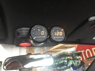
Oil pressure/oil temp on the left. Water temp/voltage gauge on the right.
IMG_1516.jpg

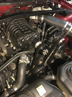
Temp sensor added to radiator upper hose.
IMG-2297.jpg
 

GlassTop09

Senior Member
Joined
May 24, 2019
Posts
1,145
Reaction score
526
Location
Farmington, NM
When I was troubleshooting my fan circuits (intermittent operation/wouldn't come on when they should) and wanted to determine if my PCM was working (sending ground signals to relays when they were supposed to) Lito sent me a tune that turned the fans on at 40 deg (essentially "On" all the time). Given everything else was working running that tune turned the fans on as soon as the car was started and told me those circuits were operational. That helped me narrow down the problem to an old fan drawing too much current. Replacing the fan with an FRPP unit and reloading the previous tune restored everything back to normal operating parameters.

Checking if the circuit is coming on "exactly" when it should is a bit of a guessing game so to make it easier I would recommend adding a temp sensor to help you monitor operation. My normal operating parameters show that my low speed comes on around 214 and then cools down to 200 (monitoring the temp gauge) before kicking off. Never really see it hit high operation.

Oil pressure/oil temp on the left. Water temp/voltage gauge on the right.
View attachment 80633

Temp sensor added to radiator upper hose.
View attachment 80636
The key is that a tuner sent you a known fan cooling profile that you have knowledge of to use in your PCM to know what\how the PCM would react to then check all the mechanical aspects of the system to know if the mechanical aspects are functioning as they should or not..................from a mechanical POV.
This still doesn't give you the tune side of this until you have the actual operational PCM fan control settings profile info in hand to then know that your issue isn't being caused\created thru the software........

IMHO this should be a requirement for all tuners to give the customer at least a copy of the actual fan speed control settings profile being used in the final tune so that the customer can\will know what\how this is set up to then have an expectation of how this will work....period. This is too important for a customer not to know.

It's 1 thing to burn the BEC terminals when you already know the PCM fan control setup is intentionally set up to run the system outside of it's design intentions beforehand......it's a whole 'nother situation to intentionally put a customer in this position w\o the customer's consent or knowledge of it............regardless of who does the tuning!

This happens FAR too often than it should be.

My tuner gives me a copy of my actual entire tune file already translated so that I can open it up in HPTuners VCM Editor software so that I can see it all.......cause according to my tuner, "You paid for the tuning & it's your car thus it's your tune. I could care less as to whomever sees the file. I have found that in the end, I end up getting more business from doing this cause it sends the message that I am very confident in my abilities to tune & isn't worried about any competition. I got nothing to hide."

His exact words. He keeps a copy of them for his records as well.

This is how I caught this w\ my car.....by using HPTuner's tune file comparison feature to compare my car's tune file w\ a sample '05 OEM SO tune file that comes w\ HPTuners VCM Editor software & saw that this had been changed to do exactly how Lito set up your "fan system checking" file.....my tuner didn't touch this part BUT Bama certainly did cause it was the Bama tune my tuner used as the base file (I had it already loaded in my PCM) & since we wasn't having any issues of overheating during the initial dyno session he assumed that all was good so didn't even look at it.... The only reason I had the Bama 91oct tune loaded up back then was to see how it would perform after I burned all the 87 oct fuel out the tank to fill up w\ 91 oct fuel prior to my dyno session at my tuner's direction (I used the original OEM tune set up for 87 oct fuel w\ the SCT Options set in it to use the FR Bullitt 85mm CAI, BBK 62mm TB, FRPIM & Kooks LTH's w\ cats so the rear O2 sensors enabled) & forgot to flash it back to stock.

Good thing for me is that I caught it all well before I began to have any of the symptoms even show up.

This is why I brought this up to bring this attention to the OP (the rest as well) because of what he typed as clues to this being a cause of his symptoms & shouldn't be overlooked.....

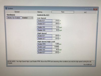
PS--for those who want it, here is a picture of an OEM fan control profile in a SO PCM for 05-09 GT taken in HPTuners VCM Editor:
OEM Spanish Oaks Fan Cooling Profile.JPG
Also just to point this out.......the low speed fan ECT target on\off settings you see in this picture represent the Ford designed\intended optimal thermal operating range for this 4.6L 3V engine......thus best efficiency out of it.
 
Last edited:

Latest posts

Support us!

Support Us - Become A Supporting Member Today!

Click Here For Details

Sponsor Links

Banner image
Back
Top