Hey everyone,
<?xml:namespace prefix = o ns = "urn:schemas-microsoft-com fficeffice" /><o></o>
I am posting some tips on the installation of my Ford Racing/Autometer Performance information computer gauge #M-10898-CPIC (Autometer # 880089) in a Roush vent pod. This will apply to the ’12 Boss, and will most likely be the same for the ’13 (as well as any 10’-14 GT or V6). I recommend that you do this when you have plenty of free time and don’t rush it if this is your first time doing this.
<o></o>

<o></o>
PART 1
<o></o>
Removal of Dash Bezel
<o></o>
The first step is to remove the dash trim bezel so you can physically install the gauge and vent pod. It comes out pretty easily – just tilt the steering wheel all the way down (not as obvious as you would think) and then grab it by the back of the bezel where it meets the speedo/tach lenses and carefully but firmly pull it straight out. Make sure you didn’t lose any of the little white rubber feet (you can see one is missing on the left gauge opening that I found in the foot well later). Next you should remove the headlamp switch assembly so you can drop the wires through when you put the trim bezel with the gauge back in. You can take the trim bezel and work on it indoors in a comfortable place.

<o></o>
Removal of the Headlamp Switch Assembly
<o></o>
There is one 7MM bolt head screw on a bracket down below on the left (that I discovered after yanking on it for a while). Pop the bottom dash panel down all the way across on the driver’s side to reveal the screw and remove it. After the screw is out simply pry the assembly out a little with your fingernails carefully pull out and let it hang by the wires.
<o></o>

<o></o>
When you are done for now it will look like this.
<o></o>

<o></o>
<o></o>
Installing the Gauge and Pod in the Trim Bezel
<o></o>
Since Roush provided very good installation instructions for this I am just going to give you some additional tips.
<o></o>

<o></o>

<o></o>
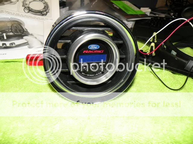
This vent pod was a very clever idea by Roush and it is a quality piece, but the only thing I did not like about it is that you push the gauge in from the front and there is nothing holding it in from the back. The gauge could work itself loose through G-forces and someone could also pull the gauge out, snip the wires, and go (what can I say, I still think like a NYer). To remedy this I took the cylindrical back bracket provided by Autometer for securing the gauge and modified it to fit since it does not fit on the vent pod because it is angled and deep.
<o></o>

<o></o>
I cut the bracket with a little <?xml:namespace prefix = st1 ns = "urn:schemas-microsoft-comffice:smarttags" /><st1:City w:st="on"><st1lace w:st="on">Stanley</st1lace></st1:City> metal saw blade on a handle that I picked up from Home Depot. One side it cut shorter to stop against one side of the pod, and then the other side is cut longer to wedge in between the gauge and pod.
<o></o>

<o></o>

<o></o>

<o></o>

<o></o>
If I had to do it again I would have cut the long side parallel to either side of the embossment down the bottom to give me more length to reach down between the gauge and the pod (you can see it fell short). It is not going anywhere but I would have preferred a perfect fit, and I am not anal enough to do it over at this point.
<o></o>
Now the gauge is firmly secured in the pod.
<o></o>

<o></o>

<o></o>
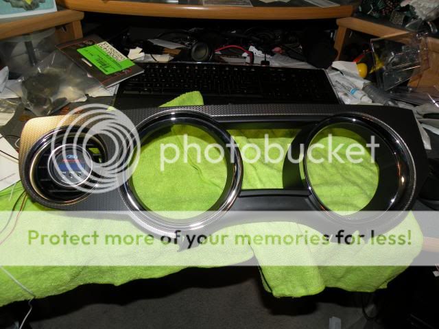
After the gauge is in the pod you put it in the vent assembly and then put it back on the trim bezel.
<o></o>
<o></o>

<o></o>

<o></o>
<o></o>
Once the gauge and pod is assembled put it to the side, since the next step is Part 2 which is the fun part of running your 12V power wire over to the passenger foot well fuse box.
<?xml:namespace prefix = o ns = "urn:schemas-microsoft-com
fficeffice" /><o></o>I am posting some tips on the installation of my Ford Racing/Autometer Performance information computer gauge #M-10898-CPIC (Autometer # 880089) in a Roush vent pod. This will apply to the ’12 Boss, and will most likely be the same for the ’13 (as well as any 10’-14 GT or V6). I recommend that you do this when you have plenty of free time and don’t rush it if this is your first time doing this.
<o
></o>
<o
></o>PART 1
<o
></o>Removal of Dash Bezel
<o
></o>The first step is to remove the dash trim bezel so you can physically install the gauge and vent pod. It comes out pretty easily – just tilt the steering wheel all the way down (not as obvious as you would think) and then grab it by the back of the bezel where it meets the speedo/tach lenses and carefully but firmly pull it straight out. Make sure you didn’t lose any of the little white rubber feet (you can see one is missing on the left gauge opening that I found in the foot well later). Next you should remove the headlamp switch assembly so you can drop the wires through when you put the trim bezel with the gauge back in. You can take the trim bezel and work on it indoors in a comfortable place.

<o
></o>Removal of the Headlamp Switch Assembly
<o
></o>There is one 7MM bolt head screw on a bracket down below on the left (that I discovered after yanking on it for a while). Pop the bottom dash panel down all the way across on the driver’s side to reveal the screw and remove it. After the screw is out simply pry the assembly out a little with your fingernails carefully pull out and let it hang by the wires.
<o
></o>
<o
></o>When you are done for now it will look like this.
<o
></o>
<o
></o><o
></o>Installing the Gauge and Pod in the Trim Bezel
<o
></o>Since Roush provided very good installation instructions for this I am just going to give you some additional tips.
<o
></o>
<o
></o>
<o
></o>This vent pod was a very clever idea by Roush and it is a quality piece, but the only thing I did not like about it is that you push the gauge in from the front and there is nothing holding it in from the back. The gauge could work itself loose through G-forces and someone could also pull the gauge out, snip the wires, and go (what can I say, I still think like a NYer). To remedy this I took the cylindrical back bracket provided by Autometer for securing the gauge and modified it to fit since it does not fit on the vent pod because it is angled and deep.
<o
></o>
<o
></o>I cut the bracket with a little <?xml:namespace prefix = st1 ns = "urn:schemas-microsoft-com
ffice:smarttags" /><st1:City w:st="on"><st1lace w:st="on">Stanley</st1lace></st1:City> metal saw blade on a handle that I picked up from Home Depot. One side it cut shorter to stop against one side of the pod, and then the other side is cut longer to wedge in between the gauge and pod.<o
></o>
<o
></o>
<o
></o>
<o
></o>
<o
></o>If I had to do it again I would have cut the long side parallel to either side of the embossment down the bottom to give me more length to reach down between the gauge and the pod (you can see it fell short). It is not going anywhere but I would have preferred a perfect fit, and I am not anal enough to do it over at this point.
<o
></o>Now the gauge is firmly secured in the pod.
<o
></o>
<o
></o>
<o
></o>After the gauge is in the pod you put it in the vent assembly and then put it back on the trim bezel.
<o
></o>
<o
></o>
<o
></o>
<o
></o>
<o
></o>Once the gauge and pod is assembled put it to the side, since the next step is Part 2 which is the fun part of running your 12V power wire over to the passenger foot well fuse box.