Planning a Ford Racing “Aluminator” Build with associated mods over the winter

Scott

Senior Member
S197 Team Member
Joined
Nov 17, 2009
Posts
2,337
Reaction score
43
Location
King City, Ontario, Canada
Is it just me or does the foot print on the 315/40ZR20’s look wider than the 325/50R15’s on the left?


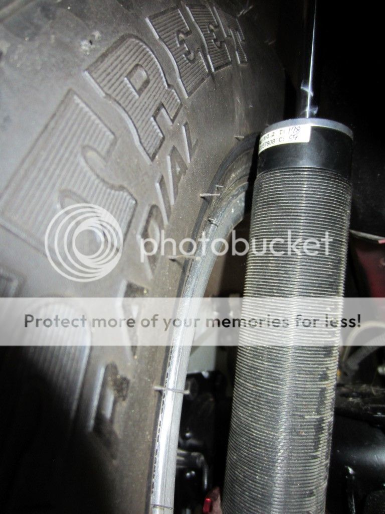
With the 15” Race Stars I needed ¼” wheel spacers to provide adequate clearance with the top of the Air Lift Performance shock body. Albeit the car is up in the air but it does not look like the spacers are required to clear the shocks. Once I drop the car down I will need to check for inner fender tire clearance.

Vossen without ¼” wheel spacers.


Race Stars with ¼” wheel spacers.


As I expected the OEM size rotors look pretty small. After the rotors pretty much filling up the opening on the Race Stars this is going to take some time to get used to. Not sure if it will ever grow on me!


bujeezus

forum member
Joined
Aug 31, 2015
Posts
3,253
Reaction score
356
Location
Alabama
3rd pic down, looks like there is a rub mark on the tire by the top of the shock body. What is that?
 

Scott

Senior Member
S197 Team Member
Joined
Nov 17, 2009
Posts
2,337
Reaction score
43
Location
King City, Ontario, Canada
3rd pic down, looks like there is a rub mark on the tire by the top of the shock body. What is that?

That was a rub mark and the reason I added 1/4" wheel spacers to work with the 15" Race Stars. Spacer is not required for shock clearance on the 20" Vossens.
 

Scott

Senior Member
S197 Team Member
Joined
Nov 17, 2009
Posts
2,337
Reaction score
43
Location
King City, Ontario, Canada
Need more pics!

Agreed, I am waiting on delivery of a BMR Sway Bar and once it gets here will button up the Watts Link and get her on the ground.


Thanks Wes

I would love to see what it looks like from the rear! I like...

Billy thanks, hopefully I will have more pics soon.

looks great with the new wheels Scott!

Nick thanks. Looks like the weather is going to be above freezing here next week so I should get some more done.

Wheels look good, I like the ones in your sig.

Thanks, I plan on keeping both sets. I have had Race Stars off and on the car for over fours years and I thought it was time for a change up. Pretty sure the OEM size rear rotors are not going to look cool with the 20's but hopefully it will grow on me.
 

Scott

Senior Member
S197 Team Member
Joined
Nov 17, 2009
Posts
2,337
Reaction score
43
Location
King City, Ontario, Canada
BMR Watts Link Install

Decided on a BMR Watts Link part number WL006 to replace the Panhard Rod and Panhard Rod Support Brace. With my Air Lift suspension clearly a Watts Link is the best way to keep the axle housing centered given the variable ride heights.

Loosely pieced together all of the components to verify nothing was missing from the hardware package. Everything looks good!

Watts Link bar from the rear looking forward.


Watts Link bar from the front looking rearward.


Jacked the front and rear of the car up and placed it on 12” wheel cribs.

It was quickly determined that my existing Steeda Sway Bar with its “Kick” in the center was not going to work with the Watts Link so I have a compatible BMR Sway Bar on order.


Removed my Steeda Panhard Bar with an 18mm socket. Removed the bolt on the passenger side of the Panhard Bar Support Brace with an 18mm socket and removed the two driver side bolts with a 15mm socket.

Now you see them driver side.


And now you don’t


Now you see them passenger side.


And now you don’t


With the car on Race Ramps Wheel Cribs and the Air Lift Performance suspension set to normal (alignment) ride height the passenger side axle clamp was installed and tightened as far outward as possible using 3/8” x 1.25” bolts with a 9/16 wrench and socket after the positioning was set to 90 degrees. The driver side axle clamp was installed as far outward as possible and also positioned to 90 degrees. The six bolts on each axle clamp were tightened in a criss-cross pattern with a 9/16” wrench and socket.

Passenger side illustrated.


The Steeda Sway Bar removed.

Watts Link cross-member was lifted up into place using the existing mounting holes from the Panhard bar and upper Panhard bar support brace. OEM hardware was reused on the driver side. Bolts, nuts and a spacer from the BMR hardware kit was used passenger side. Passenger side upper bolt was tightened to 85 ft-lbs and the passenger side lower bolt to 129 ft-lbs. Driver side bolts will be tightened when the new sway bar is installed.


Since it was easier to get at the grease fitting on the pivot it was greased before the linkages were lifted into place.


Will finish up next time in the garage. Need to install the Watts Link mounts, position and install the Linkage Bars so they are horizontal and center the housing.

Hopefully the sway bar will be here soon especially with the weather looking good for the weekend.
 

travelers

Senior Member
Joined
Apr 6, 2007
Posts
3,028
Reaction score
79
Location
Eastern Pa
That looks like BMRs normal beefy and great workmanship. Also great Install instructions with the pics, always makes it much easer to understand what is being explained.
 

Scott

Senior Member
S197 Team Member
Joined
Nov 17, 2009
Posts
2,337
Reaction score
43
Location
King City, Ontario, Canada
That looks like BMRs normal beefy and great workmanship. Also great Install instructions with the pics, always makes it much easer to understand what is being explained.

Agreed have not come across a BMR component yet that has not been well engineered and constructed. Key to this install is to literally build it on the bench first as it is much easier to see where everything goes.
 

Scott

Senior Member
S197 Team Member
Joined
Nov 17, 2009
Posts
2,337
Reaction score
43
Location
King City, Ontario, Canada
BMR Watts Link Install - Part 2

The driver side axle mount was installed on the driver side axle clamp. The axle mount was installed in the holes that positioned the linkage bar as horizontal as possible. In my case it was the 3rd holes up from the bottom. The ½” bolts were tightened using a pair of ¾” wrenches. The driver side linkage bar length was adjusted to fit and installed in the outer Watts Link Mount with a ½” x 3” bolt and washer under the poly-lock nut.


Similar to the driver side, the passenger side axle mount was installed in the holes that would position the linkage bar as horizontal as possible. In my case it was the bottom holes. The passenger side linkage bar was adjusted to fit. All bolts were tightened with a pair of ¾” wrenches.


When the pivot was assembled on the bench the bolts were snugged but not tightened. With the cross member installed the outer bolts were tightened to 35 ft-lbs using a 9/16” socket and wrench and the center bolt was tightened to 80 ft-lbs with a ¾” wrench and socket.


The axle housing was tested for center using a straight edge and a tape measure, measuring from the tire side wall to the straight edge. Passenger side was 9/16” and the driver side was 11/16”. To centre the differential the driver side linkage arm was shortened 1/16” and the passenger side lengthened 1/16”. The linkage jam nuts were then tightened with a pair of 15/16” wrenches.


Hard to get a full picture of the Watts Link while lying on my back under the car, here is the best I could do from the front looking back.


And from the back looking towards the front of the car.


All done except for tightening the driver side cross member bolts. Since they use the sway bar mounting location they can’t be done until the new Sway Bar is installed.


travelers

Senior Member
Joined
Apr 6, 2007
Posts
3,028
Reaction score
79
Location
Eastern Pa
Looking good. Did you take some axel clamp measurements so you will know if it's moving? Are you going to tack them in place?
 

Scott

Senior Member
S197 Team Member
Joined
Nov 17, 2009
Posts
2,337
Reaction score
43
Location
King City, Ontario, Canada
Looking good. Did you take some axel clamp measurements so you will know if it's moving? Are you going to tack them in place?

Did not take any measurements and was not planing to tack weld the clamps. Will take a look at them after some miles on the car and assess.
 

Scott

Senior Member
S197 Team Member
Joined
Nov 17, 2009
Posts
2,337
Reaction score
43
Location
King City, Ontario, Canada
BMR Sway Bar Install

Unpacked the box and noticed that one of the steel sleeve inserts for the mounts that attach to the relocation brackets was missing from the hardware packet. Everything else was there so with a quick call to Dylan at BMR the missing sleeve was shipped the same day.

You can see the bolt, washers and sleeve on the top right and the bolt washers and no sleeve on the top left.


Installation starts be removing the top two bolts on the driver side relocation bracket.


Even with jack stands under the rear of the subframe connectors and a floor jack under the differential it was still a challenge to get the relocation bracket bolts in and out. Upper (damper) bolt was tightened to 45 ft-lbs with a 20mm socket and the lower control arm bolt was tightened to 129 ft-lbs with a 22mm socket.


Top two bolts were removed on the passenger side relocation bracket and the passenger side sway bar bracket was installed Upper bolt was tightened to 45 ft-lbs with a 20mm socket and the lower control arm bolt was tightened to 129 ft-lbs with a 22mm socket.


After applying BMR Super Lube synthetic grease to the ID of the bushings the BMR End Links where fastened to the sway bar using 1” Energy Suspension Bushings, 3/8” Allen bolts, washers and poly-lock nuts.


The driver side 7/8” Energy Suspension Bushing was loosely installed on the bracket with 3/8” bolts, washers and poly-lock nuts.


The passenger side 7/8” Energy Suspension Bushing was loosely installed on the bracket with 3/8” bolts, washers and poly-lock nuts.


The sway bar was lifted up into the factory mounting brackets and the bolts were tightened to 45 ft-lbs using a 15mm wrench and 18mm socket.

Grease was applied to the ID of the 7/8” bushings, the steel sleeves were inserted with the threads facing inward.


The sway bar was rotated up and the ½” x 2” bolts were threaded into the sleeve. The sequence was lock washer, flat washer, sway bar, flat washer then the sleeve. The BMR instructions say “after determining which sway bar hole you want to use”…. however, there is no guidance indicating what the different holes do. I assume the shorter the bar the stiffer it becomes. I elected to mount the bar using the second holes from the end. The bolts were tightened to the sleeve using a pair of ¾” wrenches. Driver side illustrated.


The sway bar mounting bushings were then tightened with a pair of 9/16” wrenches.

Once the missing steel sleeve arrives from BMR I will finish the passenger side.
 

Scott

Senior Member
S197 Team Member
Joined
Nov 17, 2009
Posts
2,337
Reaction score
43
Location
King City, Ontario, Canada
My original Vortech intake couplings were starting to get a little dirty so I ordered some Silicone Intakes replacements. The new ones were three inches wide and I needed to reduce them to two inches so I used the “hose clamp and box cutter” method to trim off the excess width.

Original Vortech couplings.


Silicone Intakes couplings.


When I had the Vortech intake plumbing off, I took a moment to trial fit an Anderson Power Pipe. I was concerned with the wider AFCO radiator and SVT Fan in the car that the Power Pipe would not fit. But while it is a little tight it fits fine, will just need to trim the radiator shield a little so the shield will sit flat.

I am pretty sure my tuner will have visions of dollar signs when he sees me coming for an updated tune with this mod. By looks alone the Power Pipe is going to flow a lot more air than the Vortech design.


Scott

Senior Member
S197 Team Member
Joined
Nov 17, 2009
Posts
2,337
Reaction score
43
Location
King City, Ontario, Canada
Missing sleeve arrived from BMR Suspensions yesterday, thanks Dylan and I finished off the install this morning. Inserted the sleeve and attached the passenger side of the sway bar to the mount.


The four Energy Suspension bushings and the two BMR End Link Brackets were greased.

Sway Bar install complete.


While under the car I sprayed the four hemi joints on the Watts Link with Amsoil Heavy Duty Metal Protector as recommended by BMR.


Scott

Senior Member
S197 Team Member
Joined
Nov 17, 2009
Posts
2,337
Reaction score
43
Location
King City, Ontario, Canada
Dirty car first time on the ground with the Vossen wheels. Supper 4 X 4 mode with air suspension all up.


The money shot, suspension aired out.


More pictures to follow once the car is cleaned up.
 
Last edited:

Support us!

Support Us - Become A Supporting Member Today!

Click Here For Details

Sponsor Links

Banner image
Back
Top