Planning a Ford Racing “Aluminator” Build with associated mods over the winter

Scott

Senior Member
S197 Team Member
Joined
Nov 17, 2009
Posts
2,337
Reaction score
43
Location
King City, Ontario, Canada
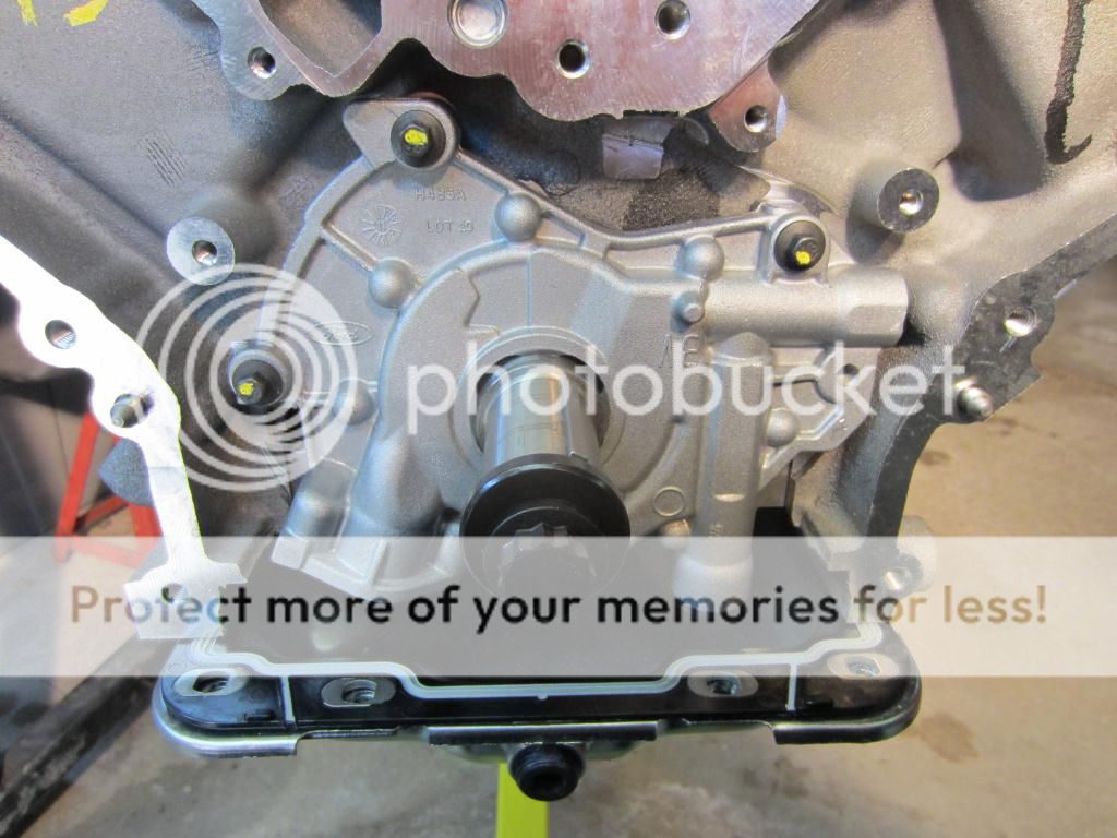
Oil Pump Modification

Thanks to the research by “One Eyed Willy” I am modifying the Oil Pump in my build to further bullet proof the pump. Originally 3V oil pump failures were attributed to the gears, as a solution many builds have gone with TSS or MMR billet replacement gears. I purchased a Triangle Speed Shop (TSS) pump with Billet Gears for my build. However, for the 2013 5.8L SVT motors Ford came out with an Oil Pump # DR3Z-6600-A that has a Billet Backing Plate. The Billet Backing Plate weighs in at just less than 12 oz. while the OEM cast plate is a little over 3 oz. On my TSS Pump the Backing Plate has been replaced with the Billet one from the 2013 SVT Pump.

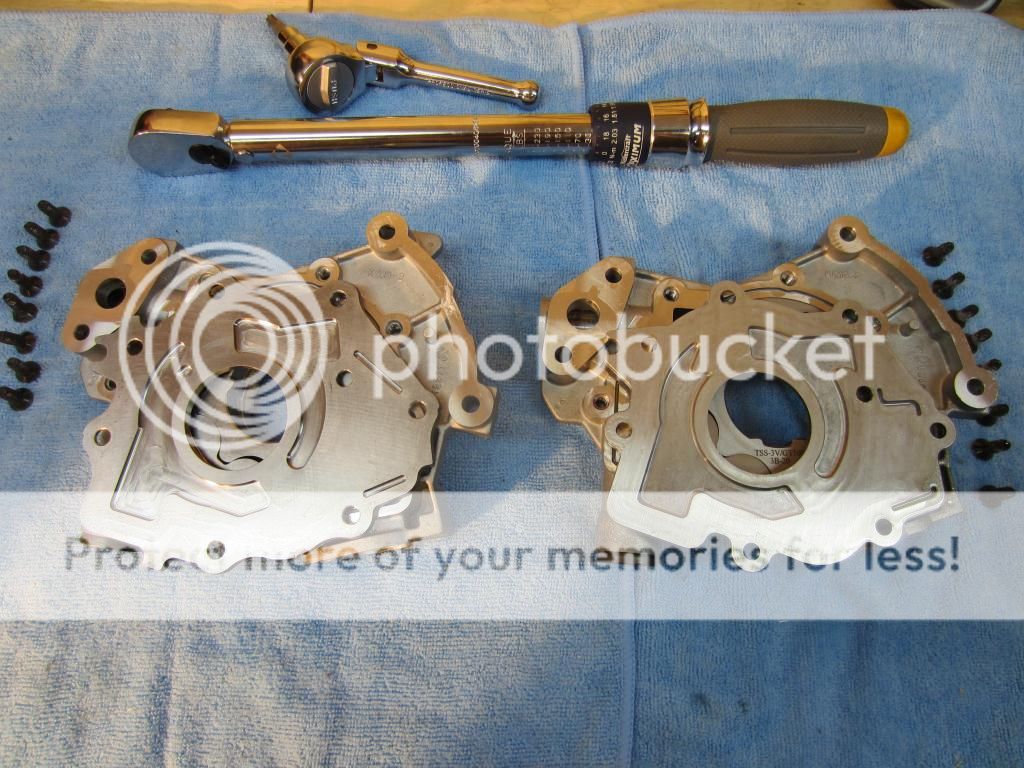
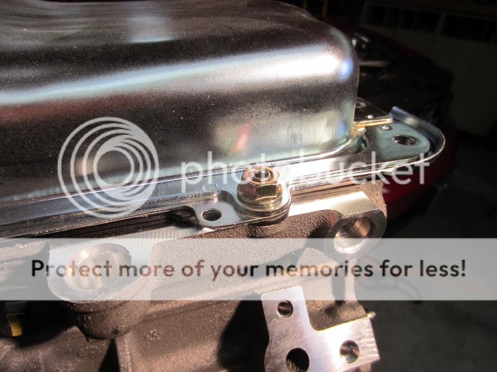
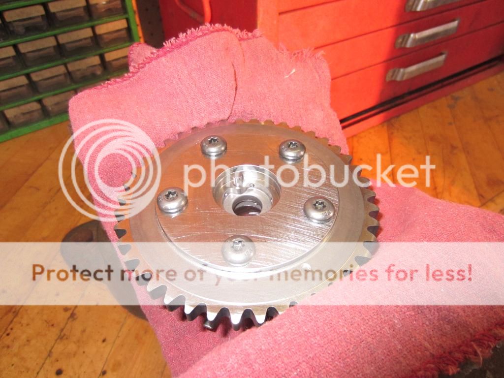
2013 SVT Pump on the top and the TSS Pump on the bottom – with covers on:

IMG_3125_zps2c31ce92.jpg


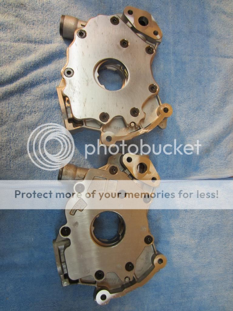
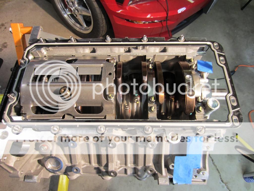
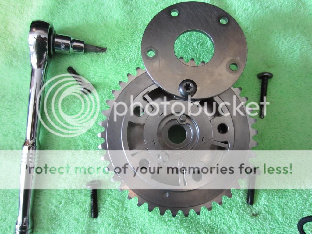
2013 SVT Pump on the left and the TSS Pump on the right – with covers off:

IMG_3130_zps5ec7241b.jpg


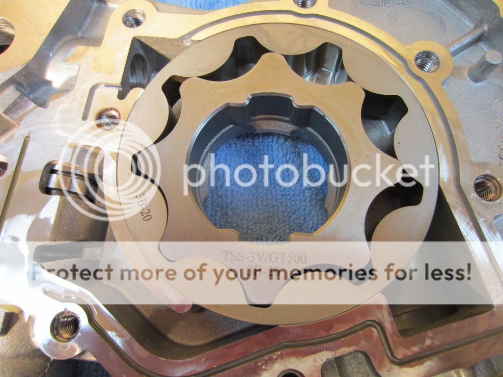
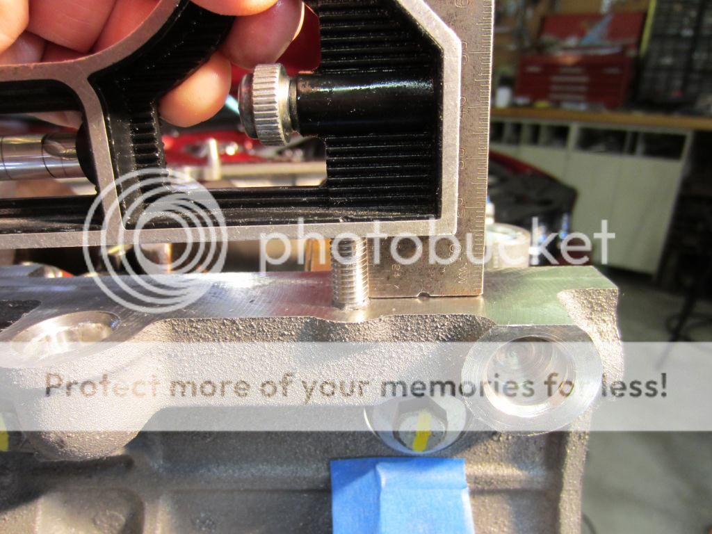
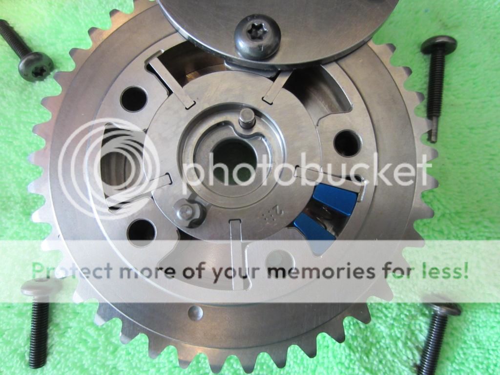
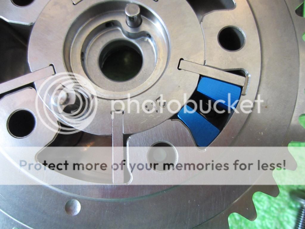
TSS Billet Oil Pump Gears. Noticed That Triangle Speed Shop used High Strength Red Thread Locker on the backing plate bolts so I will use Red in my build as well.

IMG_3134_zpsc204c24b.jpg


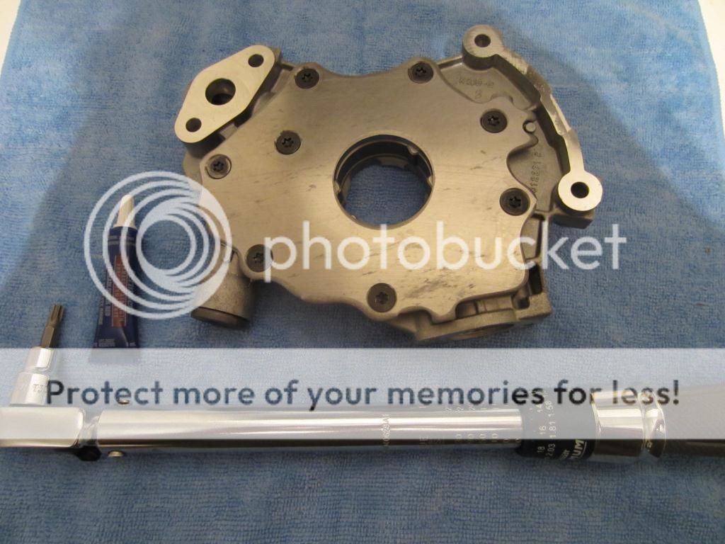
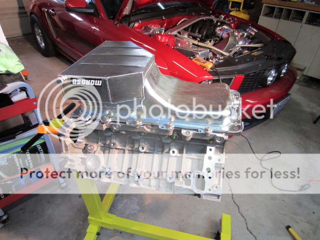
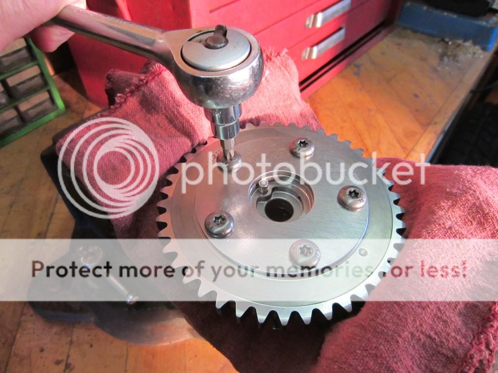
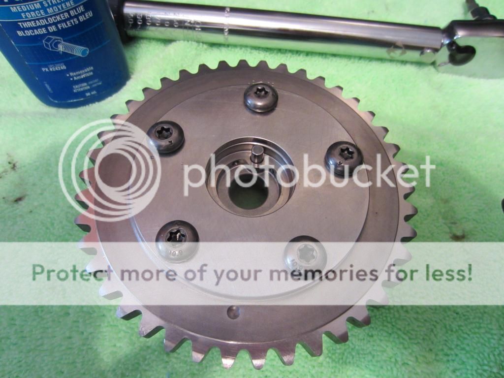
Billet Cover installed on TSS Pump (T30 Bit, torque to 89 in-lbs with High Strength Red Thread Locker)

IMG_3151_zps92783c28.jpg
 
Last edited:

Scott

Senior Member
S197 Team Member
Joined
Nov 17, 2009
Posts
2,337
Reaction score
43
Location
King City, Ontario, Canada
Canton Oil Pan Studs Installed

Wiped the engine block oil pan mounting surface with solvent and it was probably not necessary but I used a little Nickel Anti-Seize Lubricant on the Stainless Steel Studs going into the Aluminum Block. I used a 5/32” Allen Key to install the studs following Canton Racing Products Instructions – “Studs should be screwed in far enough to be well seated while leaving enough of a protrusion out of the engine block to mount the windage tray, oil pan and gaskets”.

Canton Part Number for the Oil Pan Stud Kit is 22-364.

IMG_2696.jpg


I temporarily installed an OEM gasket, part number 3L3Z-6710-AA, Moroso Oil Pan part number 20548 and tightened the nuts (13mm) enough to establish the installed depth of the studs.

IMG_3182_zps6598acb2.jpg


IMG_3160_zpsd4f917e4.jpg


The height I adjusted all the studs to was 5/8 inch.

IMG_3174_zps1275d8aa.jpg


IMG_3170_zps66e45ffc.jpg
 

Scott

Senior Member
S197 Team Member
Joined
Nov 17, 2009
Posts
2,337
Reaction score
43
Location
King City, Ontario, Canada
Cylinder Head Alignment Dowels Installed

Not much progress today, I did manage to sneak away from the Honey-Do-List long enough to get the Cylinder Head Alignment Dowels installed.

The Aluminator Short Block did not come with Cylinder Head Alignment Dowels. The part number for the required dowels is F8AZ-6A008-AA (package of 4):

F8AZ-6A008-AA_zps370ef4ee.jpg


Now you don’t see them:

IMG_3188_zps99098b67.jpg


Now you do:

IMG_3202_zpsb0388d0d.jpg
 

BruceH

BBB Big Bore Boss 322
Joined
Sep 13, 2009
Posts
13,801
Reaction score
14
Location
Pacific Northwest
Nice progress and build. Is there any time frame for completion? You have an awful lot of patience, lol.
 

Scott

Senior Member
S197 Team Member
Joined
Nov 17, 2009
Posts
2,337
Reaction score
43
Location
King City, Ontario, Canada
Installed FRPP 3V Cam Phaser Limiters

In preparation for degreeing the Comp Cams I followed the Ford Racing instructions on how to install the 3V Cam Phaser Limiters. The Limiters where included with the FRPP High Flow CNC Cylinder Heads, part numbers M-6049-463VP3 (RH) and M-6050-463VP3 (LH).

3V Cam Phaser Limiters:

IMG_2857.jpg


Place the Cam Phasers carefully in a bench vice to break the bolts loose with a T30 Bit:

IMG_3220_zps5f321b2f.jpg


Loosen all 5 bolts, but only remove the 3 short bolts and 1 long bolt, leaving the 1 long bolt that goes through the phaser and comes out the other side where it hooks and holds the spring for the phaser assembly in tension. The other long bolt is also used to add spring tension and the spring will need to be pried out to reinstall this bolt. Only loosen the long bolt that hooks the spring enough to allow you to rotate the rear cover out of the way.

IMG_3223_zpsd1677adb.jpg


Remove the Phaser from the vice and continue working on a bench. Rotate the backing plate slowly until a small spring forces a check valve out. Stop; do not disassemble the phaser any further.
With the backing plate rotated out of the way you can see that there are five inner vanes that are positioned against the outer portion of the gear.

IMG_3229_zps05a992cf.jpg


Quoting from the FRPP Instructions: “The limiters are precision machined to fit in one section better than the rest. The limiter should be installed into the void that has the vane sitting flush with the fixed outer portion of the gear. The little spring fits in the machined pocket on both pieces. Install the spring ahead of time and keep pressure on it as you slide in the unit. There is a small slot cut into the one piece that corresponds with the oil hole in the inner gear. Make sure this piece is installed and the oil hole is uncovered. At this point you are all done and can re-install the small piston, spring and check seat. Then you can rotate the back plate back on the gear and re-install the other bolts.”

The finished install before the cover is replaced looks like this:

IMG_3234_zps2bea43fe.jpg


IMG_3236_zpsc036f935.jpg


With a small spot of Medium Strength Blue Thread Locker on the bolts, torque them to 145 in-lbs with a T30 Bit. Voila you now have a fully assembled “limited” Cam Phaser, now just repeat for the other Phaser:

IMG_3245_zps56b62193.jpg
 

Scott

Senior Member
S197 Team Member
Joined
Nov 17, 2009
Posts
2,337
Reaction score
43
Location
King City, Ontario, Canada
Oil Pump Installed

Got a few minutes in the garage this morning.

The Short Block came with a new Oil Pump but it was not equipped with Billet Gears. The OEM Pump was removed and replaced with a Triangle Speed Shop Oil Pump (with Billet Gears) that has been modified by the addition of a Billet Backing Plate. The three bolts were torque to 89 in-lbs after application of Medium Strength Blue Thread Locker with an 8mm socket.

OEM Aluminator Oil Pump:

IMG_3215_zpsffc7015f.jpg


Oil Pump Removed

IMG_3249_zpsabd32863.jpg


TSS Oil Pump with Billet Gears and Billet Backing Plate installed:

IMG_3252_zps25f0efcb.jpg


Next up is to measure the oil pick up tube to pan bottom clearance.
 

Scott

Senior Member
S197 Team Member
Joined
Nov 17, 2009
Posts
2,337
Reaction score
43
Location
King City, Ontario, Canada
Oil Pickup Tube to Pan Clearance Checking – The “Play-Doh” Method

Play-Doh Method Exotic Tools

IMG_3262_zps2b6e95cd.jpg


Oil Pickup Tube “Business End” was covered with black electrical tape to prevent entry of contaminants i.e. Play-Doh. Installed and torqued at the Oil Pump to 89 in-lbs. using an 8mm socket and torqued at the Oil Pump Pickup Tube Standoff to 25 NM - 18 ft-lbs using a 10mm socket.

IMG_3264_zps9fd05e96.jpg


Lump of Play-Doh positioned on the Oil Pickup Tube.

IMG_3277_zps3baef162.jpg


Oil Pan Gasket and Oil Pan carefully installed. Oil Pan was torqued in three stages with a 13mm socket following Ford Instructions (excluding the Timing Cover Positions Bolts 13-16) Stage 1 – 18 lb-ins., Stage 2 – 15 ft-lbs. and Stage 3 – Tighten an Additional 60 Degrees.

Pan was carefully removed to expose compressed Play-Doh

IMG_3282_zps64ef6f52.jpg


Play-Doh carefully removed from Oil Pickup Tube, a cross section was cut at the thinnest area and thickness measured. Came out to 0.321”. The recommended clearance range is .270” to .375”. My Standoff is within the acceptable range and no machining is required.

IMG_3284_zps737f0cca.jpg


My wife is a Kindergarten Teacher and I was able to return the stolen Play-Doh without detection. This is good news as I will live to build another day! lol
 

Scott

Senior Member
S197 Team Member
Joined
Nov 17, 2009
Posts
2,337
Reaction score
43
Location
King City, Ontario, Canada
Dipped a new O-Ring, part number F5RZ-6626-B in motor oil and installed it on the Pickup Tube. Tightened the Pickup Tube to Oil Pump Bolts with an 8mm socket to 89 ins. lbs. and the Oil Pump Tube Standoff Bolt with a 10mm socket to 18 ft. lbs.

IMG_3327_zps5f3521bc.jpg


As guru Corky Bell said, "Studs are an engineer's design. A bolt is the marketing compromise."

I did not chase the block with a M11 X 1.5 Bottoming Tap. The only tap I could get my hands on just started to engage the threads when the end of the tap was about ¼” from the block deck. The ARP studs (part number 256-4202) where easily turned in by hand with a 3/16 Allen Handle according to ARP instructions “HAND TIGHT ONLY”. Once bottomed I verified that the height from the block deck to the top of the studs were equal.

Right Hand (passenger side)

IMG_3301_zps8d687373.jpg


Left Hand (driver side)

IMG_3333_zps21d79b05.jpg


I found the FRPP 3V Head Gasket and Bolt Kit part number M-6067-3V46 to be the most cost effective way of procuring Head Gaskets even though the TTY Bolts in the kit are not used.

Right Hand Head Gasket, Part Number 4R3E-6051-BG

IMG_3342_zps2828fbaf.jpg


Left Hand Head Gasket, Part Number 4R3E-6083-BG

IMG_3338_zpsbfbd6bec.jpg


Right Hand Cylinder Head FRPP Part Number M-6049-463VP3

IMG_3346_zpsf67ac812.jpg


IMG_3353_zpsd5510fad.jpg


IMG_3361_zpsf0f4a716.jpg


Left Hand Cylinder Head FRPP Part Number M-6050-463VP3

IMG_3373_zps6b138203.jpg


IMG_3376_zpsf125456d.jpg


IMG_3382_zps001c1143.jpg


Starting to look like an engine. I am excited. lol

Next up torque the ARP Head Studs.

IMG_3396_zps8dba2ab5.jpg
 
Last edited by a moderator:

jojobee

Member
Joined
Sep 29, 2011
Posts
69
Reaction score
0
This is a fantastic thread, awesome details.
Thanks for sharing and keep it coming :)
 

Scott

Senior Member
S197 Team Member
Joined
Nov 17, 2009
Posts
2,337
Reaction score
43
Location
King City, Ontario, Canada
Cylinder Head Install

Both cylinder heads where installed with ARP Ultra-Torque Fastener Assembly Lubricant on the threads, washers and nuts. All nuts were tightened with a 9/16” 12 point deep socket in four stages following the recommended sequence: Stage 1 - 15 NM (approx 11 ft-lbs), Stage 2 – 30 ft-lbs., Stage 3 – 70 ft-lbs. and Stage 4 – 100 ft-lbs.

ARP Ultra-Torque Fastener Assembly Lubricant part number 100-9910

IMG_2706.jpg


Right Hand Cylinder Head

IMG_3401_zpscb424c56.jpg


Left Hand Cylinder Head

IMG_3406_zps90c676a7.jpg
 

Scott

Senior Member
S197 Team Member
Joined
Nov 17, 2009
Posts
2,337
Reaction score
43
Location
King City, Ontario, Canada
VCT Housing Install

Both VCT housing were installed with new OEM gaskets, Right Hand 3L3Z-6C285-AA and Left Hand 3L3Z-6C286-EA using an 8MM socket, bolts were tightened to 89 in-lbs.

VCT Housing Gaskets

IMG_3410_zps183670fb.jpg


Right Hand VCT Housing

IMG_3424_zpsa105c20a.jpg


Left Hand VCT Housing

IMG_3413_zps18e1b566.jpg
 

Scott

Senior Member
S197 Team Member
Joined
Nov 17, 2009
Posts
2,337
Reaction score
43
Location
King City, Ontario, Canada
Lash Adjusters Installed

24 new Lash Adjusters part number 5L1Z-6500-A where submerged in Engine Break-In Oil and pumped 3 or 4 times to purge the air.

Lash Adjusters 5L1Z-6500-A

IMG_3429_zpsfd1bf0e4.jpg


Lash Adjusters Primed in Break-In Oil

IMG_3457_zps9475a65c.jpg


RH Lash Adjusters Installed

IMG_3450_zpsda2deca1.jpg


IMG_3468_zps05a33f4f.jpg


LH Lash Adjusters Installed

IMG_3466_zps2cf5bee1.jpg
 

Mike K

WANNA BE FAST
Joined
Apr 8, 2010
Posts
11,404
Reaction score
9
Location
Richfield, MN
Great thread. This should almost be a sticky. Its basically a step by step build with part numbers.
 

Support us!

Support Us - Become A Supporting Member Today!

Click Here For Details

Sponsor Links

Banner image
Back
Top