Maybe airlift should look into making a custom visor for the drivers side that has the buttons integrated in... Like some come now a days with buttons that are programmable for garage doors and things like that.. Just an idea.
You are using an out of date browser. It may not display this or other websites correctly.
You should upgrade or use an alternative browser.
You should upgrade or use an alternative browser.
Air Lift Install - Here we go slow but steady!
- Thread starter Scott
- Start date
Wes06
forum member
- Joined
- Jan 21, 2012
- Posts
- 5,383
- Reaction score
- 59
last i heard they were busy making an app and dongle for phone/tablet control.
btw jeremy, how far is it?
btw jeremy, how far is it?
Jeremy@AirLift
forum member
last i heard they were busy making an app and dongle for phone/tablet control.
btw jeremy, how far is it?
Just had to mention dongle didn't you! We are still working on it, Apple and Droid can be a bit of a hassle to work with.
Air Lift Install - Here we go slow but steady! - Continued #3
Picked up the Air Lift 2.5 gallon polished aluminum tank and a few ¼” NPTM by ¼” PTC fittings over the weekend, part number 12958.

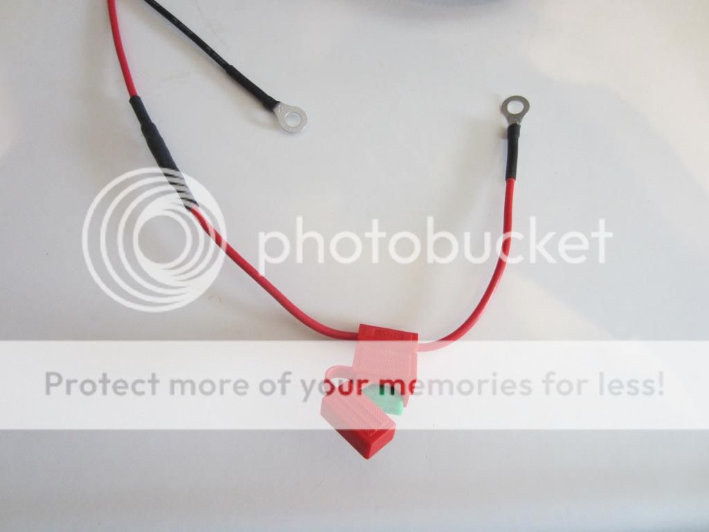
Prepared the wiring harness by terminating the wire ends with the appropriate connectors. Where possible connections were soldered and finished with double wall shrink tubing. Consistent with Air Lift instructions the positive and negative wires will be connected directly to the battery. Since my battery is trunk mounted the majority of the harness will be coiled and left in the bottom of the tire well.
Battery connections wires where terminated with 10 – 12 AWG Eyelet Connectors and an ATO Fuse Holder with a 30 AMP Fuse on the positive wire.
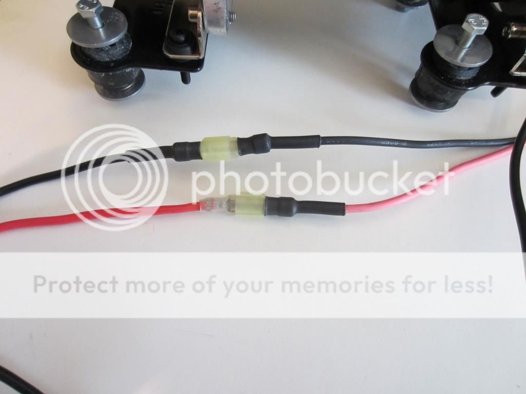
Compressor harness wires were terminated with male (positive) and female (negative) 10 -12 AWG Quick Disconnects.

The positive Compressor wire was left as provided by VIAIR with a 10 – 12 AWG female Quick Disconnect. The Eyelet connector on the ground wire was replaced with a 10 – 12 AWG male Quick Disconnect.

Compressor connected to harness.
The required “key on (power while cranking also) source” will be a white FPDM wire. I will terminate the Air Lift harness wire destined for the key on source when the harness is installed and the wire tap added to the FPDM harness.
Picked up the Air Lift 2.5 gallon polished aluminum tank and a few ¼” NPTM by ¼” PTC fittings over the weekend, part number 12958.

Prepared the wiring harness by terminating the wire ends with the appropriate connectors. Where possible connections were soldered and finished with double wall shrink tubing. Consistent with Air Lift instructions the positive and negative wires will be connected directly to the battery. Since my battery is trunk mounted the majority of the harness will be coiled and left in the bottom of the tire well.
Battery connections wires where terminated with 10 – 12 AWG Eyelet Connectors and an ATO Fuse Holder with a 30 AMP Fuse on the positive wire.

Compressor harness wires were terminated with male (positive) and female (negative) 10 -12 AWG Quick Disconnects.

The positive Compressor wire was left as provided by VIAIR with a 10 – 12 AWG female Quick Disconnect. The Eyelet connector on the ground wire was replaced with a 10 – 12 AWG male Quick Disconnect.

Compressor connected to harness.

The required “key on (power while cranking also) source” will be a white FPDM wire. I will terminate the Air Lift harness wire destined for the key on source when the harness is installed and the wire tap added to the FPDM harness.
MELLOWYELLOW06
forum member
Looking good, never got around to doing it to mellow 06
But mellow15 is a whole new story for the SEMA 2014 booth
But mellow15 is a whole new story for the SEMA 2014 booth
Looking good, never got around to doing it to mellow 06
But mellow15 is a whole new story for the SEMA 2014 booth
Thanks! Guess we will have to wait until November for Air Lift pictures of mellow15.
Air Lift Install - Here we go slow but steady! Continued #4
Started in the trunk today, removed the back panel.

Removed the battery, disassembled the battery box and removed the carpeting.

Cleared the way in the tire well by removing the wheel wrench, jack and spare tire. Likely will not miss the spare as I am pretty sure it will not mix with the 14” brakes on the front.

And just for inspirations placed the VIAIR compressor and Air Lift Tank in the trunk.
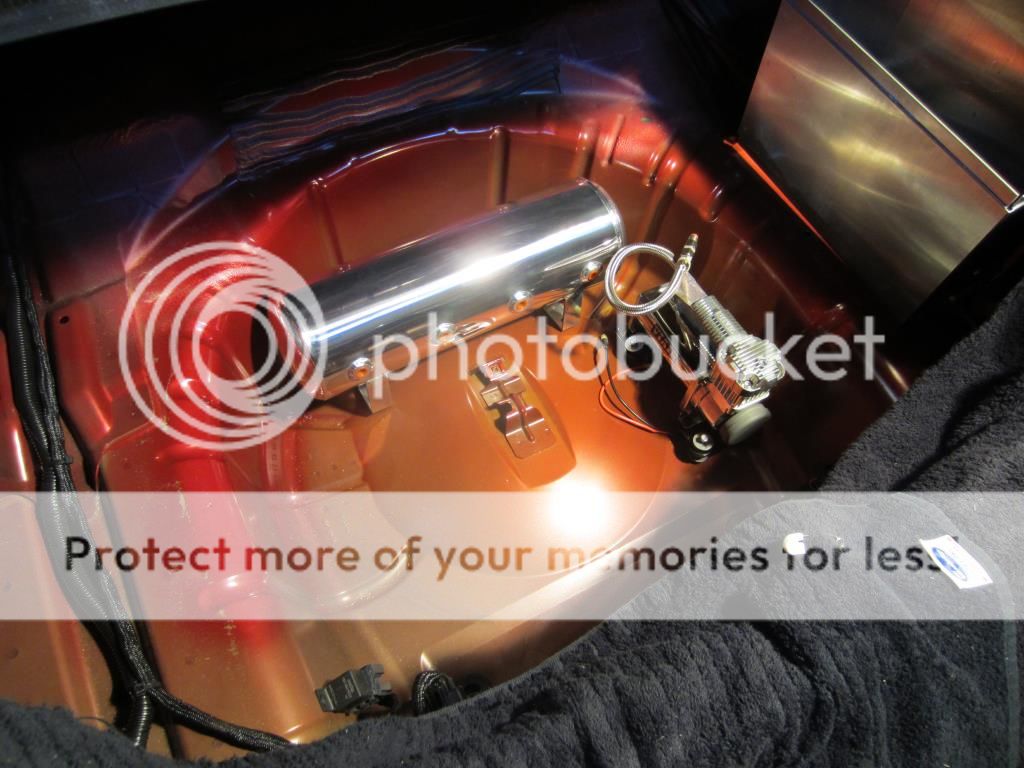
At this juncture it is not clear whether I will be able to mount the tank and compressor on ½” plywood and still remain below the trunk floor level. Definitely some more measuring to be done with a straight edge spanning the opening.
Turned to preparing the interior for routing the air lines from the struts. Removed the floor mats, door scuff plates, kick panels, rear seat bottom and quarter trim panels.
Driver’s side door scuff plate.

Passenger’s side kick panel.

Driver’s side quarter trim panel.

Next up running the air lines through the cabin.
Wes06
forum member
- Joined
- Jan 21, 2012
- Posts
- 5,383
- Reaction score
- 59
Did you measure to see how much the isolator kit raises the compressor from stock height?
I'd like to know so I can figure out if I need to mod my mounting setup or if it'll be fine
I'd like to know so I can figure out if I need to mod my mounting setup or if it'll be fine
Just measured it for you and the isolator kit adds one inch to the total height of the compressor.
Great pics and progress so far Scott!
Jeremy, thanks. Don't know how but I missed seeing your reply until today.
Air Lift Install - Here we go slow but steady! - Continued #5
Using the provided template to locate the mounting holes, mounted the manifold in the tire well with the provided self taping screws and a 3/8” nut driver. Center punched and drilled 9/64” pilot holes. When printing the template from a PDF file make sure your printer is set to “actual size” to get the correct dimensions of the template.
Template

Manifold mounted.

Mounted the relay to the right of the manifold.

Routed the passenger’s side air line through the frequently used OEM nipple right among the two 1 gauge and one 4 gauge welding cables used for my battery relocation.

Air line from inside the cabin.

Inside the cabin the passenger side air line was secured with cable ties every foot or so to the battery cables running back to the trunk.

Underneath the rear seat I left a small loop of air line that could be pulled to the front or back if air line connections ever leak and need to be repaired. Thought this would be much easier than running a whole new air line.

Today I also prepared the tank for mounting. In preparing the tank (Air Lift part number 12958) with my configuration I installed two ¼” NPTM plugs in the two left holes and a 90 Degree swivel ¼” NPTM by ¼ PTC fitting in the second hole from the right which will be routed to the tank port on the manifold. A couple of revolutions of Teflon tape were applied to all fittings and fittings were tightened down with a 9/16” wrench.
The ¼” NPTM swivel fitting from the VIAIR compressor will be installed in the remaining side hole on the right when the tank and compressor are mounted.

A ¼” NPTM 90 Degree swivel by ¼” PTC fitting was installed in the tank bottom hole.

great write up Scott, going to make doing my install one of these days easy..
Thanks James, we try.
Air Lift Install - Here we go slow but steady! - Continued #6
Ran into an “opportunity” today with the air tank, the bottom 90 degree elbow I installed hangs down too low and the air tank when positioned in the tire well rests on the fitting rather than the tank feet. This is because of the bulge in the center of the tire well. I have a shorter elbow to try, but it doesn’t look good.
Routed the driver’s side air line from the strut through the large OEM grommet.

Driver’s side air line from inside the cabin.

Driver’s side air line was cable tied to the wire bundle that runs along the rocker panel towards the trunk.

Just as I did on the passenger’s side I made a small loop of air line under the rear seat.

Scott, have you thought about using a spacer on the bottom of the leg where it bolts up on the floor to raise the tank up enough to clear fitting?
spacer should make it an easy fix...would be better than changing out the 90 on the bottom.. just an idea..
Yes, but the issue with the spacer is that I want to keep the tank below the oem trunk floor. Wes06 built a platform and raised the trunk floor. I was hoping not to have to do that. If I can't get it to work with the space in the tire well I may have to mount the tank behind the seat. GallopingFord has the same tank in the tire well, will have to check with Cam on whether he is using the bottom fitting for a drain/fill line.
UltraKla$$ic
PERENNIAL WAXXER
Nice write up!!! Thanks!
Get a BFH and flatten the wheel well area. That's what I did with mine to mount the battery there.
Earl
Earl
Yes, but the issue with the spacer is that I want to keep the tank below the oem trunk floor. Wes06 built a platform and raised the trunk floor. I was hoping not to have to do that. If I can't get it to work with the space in the tire well I may have to mount the tank behind the seat. GallopingFord has the same tank in the tire well, will have to check with Cam on whether he is using the bottom fitting for a drain/fill line.
might only need to be only one or two washers to raise it enough, might want to put one washer at a time under each side/foot of the tank to see if it would clear, just an idea.
Similar threads
- Replies
- 2
- Views
- 1K
Support us!
Support Us - Become A Supporting Member Today!
Click Here For Details
Sponsor Links