Lunati VooDoo #21270700 Camshafts

GlassTop09

Senior Member
Joined
May 24, 2019
Posts
1,145
Reaction score
526
Location
Farmington, NM
FYI..................

Here is a drawing of how this 3D Smoothing is applied:
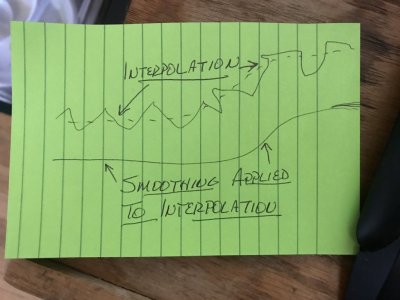
3D Smoothing Diagram.JPGThe software looks at the interpolated map settings (the solid line) to determine the underlying X-Y axis scaling (the dotted line), then will readjust the interpolated map settings (adding to all that fall below the underlying X-Y axis scaling line & subtracting to all that fall above the underlying X-Y axis scaling line) until all match up to the underlying X-Y scaling line so now the ECU will track along the actual underlying X-Y axis scaling line instead of tracking along the actual interpolated scaling line that was tracking along the underlying true X-Y axis scaling line.....thus the ECU tracking is "smoothed out" along the same map profile.......applied in 3D maps such as the knock sensor noise sensitivity threshold maps (also in several others as well) can give some tangible benefits that can be easily viewed on a datalog as follows:
Hiil Clinb Datalog Knock Sensor Activity Prior 3D Smoothing.JPG Hill Climb Datalog Knock Sensor Activity Post 3D Smoothing.JPG
The picture on the left is showing a section of datalog that engine was under high load, low RPM operation climbing a very steep grade in 5th gear (intentional to test tuning under knock sensor control). As you can see, we're riding the very edge of the cyl knock sensor noise sensitivity threshold settings that hadn't had this 3D smoothing applied yet.......these results aren't bad at all......actually very good (knock is present only in 3 cyls....mostly #3 cyl w\ a couple in #5 cyl & a couple in #8 cyl for roughly a .5*\sec retard blip intervals.....this is the strength of using Per Cyl Knock Mode. Imagine how much more power would be cut if this was in Global Mode.......).
Now contrast this w\ the picture on the right.......from my last datalog showing engine was under the same high load, low RPM operation climbing the exact same steep grade in 5th gear but the same cyl knock sensitivity threshold maps used in the datalog prior had 3D Smoothing applied to them & nothing else in this 1 w\ all other settings in tune file untouched.......

Even w\ my tune set in Per Cyl Knock Mode, there is a clear advantage gained from applying this as this cleaned up the knock activity by a lot thus engine had more net available HP\TQ under the curve now than it did prior under the same engine loading conditions by allowing the ECU to more accurately "ride the edge". This is where it's at........the closer to the edge of knock you can ride w\o tipping over, the more available & peak HP\TQ can be squeezed out......safely. When this 3D Smoothing is also combined in all other maps as well you can potentially squeeze even more out & do it safely & efficiently on top of it all........while also improving the "driving feel" from engine available HP\TQ being very smoothly applied essentially across the board from very smooth ECU tracking thus calc's across all 2D & 3D map X-Y axis scaling data.

Yeah, some will call this nitpicking, but you can't deny the results either, no matter how small. When tuning for a living, this is the dilemma a tuner will face as this can be tedious & somewhat time consuming to do well initially thus a cost\benefit analysis vs profit.......at the same time, a consumer will want this level of tuning, but the issue of cost\benefit analysis also comes into play thus a consensus balance has to be worked out by both parties........

Posted for informational purposes.
 

GlassTop09

Senior Member
Joined
May 24, 2019
Posts
1,145
Reaction score
526
Location
Farmington, NM
Ok folks,

After looking thru my latest tune revision flashed in today (made a small correction to tire revs\mi....rounded the calc'd result down to lower whole number instead of allowing HPTuners Editor to round it up to higher whole number....this put the IC speedo difference to within 2 MPH of ECU speedo output) after getting back in town yesterday from attending a wedding in Houston, TX & datalogged\tested to operate fine, I'm calling it a done deal as of now since I've gotten everything well within & operating to my level of satisfaction across the board.

The far & away difference that I've found in tuning my Stang thru this Spanish Oaks ECU is the importance of getting all the front-end tuning right in tune calibration (MAF, LWFM, MAF Adaption, all SD tuning-particularly the TB PTA\EA in-tune mapping to fit the actual physical TB used, TB transient fuel tuning, fuel stoich AFR, fuel inj EOIT ref CA, fuel inj data to match the fuel injectors, O2 sensor TD mapping, O2 sensor startup OL-CL threshold info & OL-PE threshold, Dynamic Airflow to match IM inner volume post TB, fuel pump control data, etc) so any back end tuning (spark advance\retard, VCT, knock sensor operation, OL-WOT PE, etc) can be done w\ little to no issue(s) w\relative ease & very accurately......even w\ using the NB O2 sensors STFT+LTFT corrections in place of a WB O2 sensor for the most part.

What I'm gonna type next I'm sure will rub some wrong.......but these ECUs actually operate primarily using all the in-tune SD programming\calc's in tandem w\ the LWFM airmass map for any\all initial airmass calculations along w\ its VE load calcs using engine's ideal displacement airmass as SD is always proactive thus is predictive, not the MAF!

It is a mistake to think the MAF is the primary driver\operator within a SO ECU tune calibration file.......fact.

What the MAF IS used for in this ECU is an airmass IAT & density REACTIVE back check\correction in real time to the SD predictive airmass\VE load calcs.......as long as MAF Adaption is left enabled in tune calibration file......w\o MAF Adaption enabled, the ECU cannot correct any found differences in SD-based predictive airmass\VE load calcs using the TB's in-tune PTA\EA mapping & LWFM airmass table vs the actual MAF read reactive airmass\VE load calcs from actual TB's physical PTA\EA sizing at the same commanded TB TPS angle, thus the ECU will fail the MAF if it sees this being too far out of bounds vs the in-tune SD predictive airmass\VE load calcs & fall back on the predictive SD airmass\VE load calcs thus the MAF won't get used at all! This is what a lot of tuners are actually trying to get around by intentionally inflating the IPC Wheel TQ Error safety numbers (ECU tracks the generated TQ output differences between the SD airmass calcs vs the MAF airmass calcs since this ECU uses DBW throttle control......designed to prevent an engine RPM runaway from loss of TB airmass control) high enough to prevent the ECU from going into Limp Mode if this setting is exceeded.......instead of just ensuring\doing all the proper up front SD tuning along w\ a properly tuned TB PTA\EA mapping that matches the physical TB's size being used & a LWFM airmass map that matches the properly tuned MAF calibration table's output from idle to WOT.

This, IMHO, has been widely misunderstood for quite some time & is the main reason why so many tuners are missing the mark especially when emissions are factored in & to a very large degree, the max available HP\TQ output from these 3V's......particularly street driven NA 3V's. In order for the ECU's SD predictive airmass calcs to be good, ALL OF THE SD FRONT-END TUNING HAS TO BE ACCURATE IN THE TUNE CALIBRATION TO MATCH THE MAF OR THE ECU WILL FAIL THE MAF, NOT USE IT FOR ANY CORRECTION & FALL BACK ON THE PREDICTIVE IN-TUNE SD AIRMASS TUNING......REGARDLESS OF HOW BAD THE PREDICTIVE SD TUNING IS\MAY BE.
All fueling is initially applied based off the in-tune predictive SD airmass modeling calcs being actually used thru the EQ Ratio Lambda equation formula thus is a constant.......which makes getting all the predictive SD in-tune tuning parameters accurate PARAMOUNT.

This is how all these SO ECU's underlying OS programming coding is set up to operate. The ECU is programmed to still run if a MAF sensor shows itself to become defective\inaccurate.

So, the predictive SD in-tune tuning is very important to get right for max available\peak HP\TQ output as well as for emissions.......the closer all this SD tuning is mimicking the actual MAF calibration tables, the more usable HP\TQ you'll squeeze out along w\ better LEGAL emissions control\compliance......fact.

This is what I've learned\seen\witnessed from researching, testing then putting into practice & learning from others while doing my own tuning on my car myself.......at 167,654+ mi on her so mileage ain't a limiting factor.........

In the end I believe this is where the US EPA is gonna push this to once they get all the OEM ECU tuning equipment\software suppliers to rearrange their products to allow the EPA to track back to the individual(s) tuning interface device thus ID the actual individual\place of commerce who is still putting out faulty tuning that continues to fail the CAA regs outright or assists in usage of defeat devices\methods thus failing the CAA regs.

Now to find a shop in Albuquerque where I can get her dyno'd to see what the HP\TQ curves actually look like off my tuning..............
 

GlassTop09

Senior Member
Joined
May 24, 2019
Posts
1,145
Reaction score
526
Location
Farmington, NM
No leaks, no drips so no errors so far......but for any future gear\diff work I'll only use the FP 8.8" gear install kits as they use all Timken bearings.
On this note as well, I just can't get this out of my head since installing the Motive Gear F888390 3.91 actual full hunting gear set using the existing Motive Gear ring & pinion install kit (pinion & carrier bearings mostly) from the Richmond Gear EXCEL 3.90 (3.89 actual non hunting) gear set install done by a shop that whined badly........
So, I have already purchased a Ford Performance M-4210-B2 8.8" Ring & Pinion install kit & have it in hand to replace all the old pinion & carrier bearings\races in my rear axle so that I can relax & let this go knowing all has been finally done correctly. This is the FP 8.8" kit that is using the Ford designed Hi Tq inner\outer pinion bearings (also why it costs more than all the rest.......) that Ford used in the 07-14 GT500 8.8" axles but redesigned to use in all other 05-14 Ford 8.8" axles w\o needing the additional spacer.

Yep, I should've done this when I did the Motive 3.91 gear install but I didn't........the advent of me feeling these pinion bearings "ratcheting" during rotation after running too tight of an initial preload never set too well w\ me (in hindsight this ratcheting should've never happened if bearings\races were properly lapped\matched thus was a red flag......but I chose to ignore it at that time after a proper resetting of preload rolled smoothly by hand........).

Gonna wait on the weather to cool down some before I do this & will post what I find along w\ the results.
 

GlassTop09

Senior Member
Joined
May 24, 2019
Posts
1,145
Reaction score
526
Location
Farmington, NM
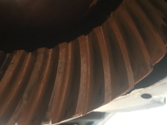
Started the rear axle bearing replacement yesterday. Got all torn down (ran a pattern check on the .029"PD .009" BL set prior for reference), both pinion bearing races driven out & pulled inner pinion bearing off pinion gear & both carrier bearings off the Tru-Trac diff & ran a good visual inspection of all races............
14 Month Motive 3.91 Coast Side .029 PD .009 BL Pattern.JPG 14 Month Motive 3.91 Drive Side .029 PD .009 BL Pattern.JPG
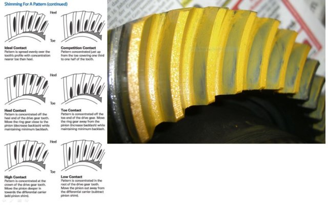
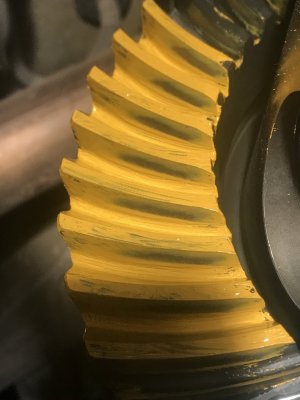
This .029" PD, .009" BL set pattern check shows the overall gear mesh alignment is decent (I intend to run these slightly on the toe side of center as this was reported thru research to be the best way to run a 5-cut, face milled set of gears) coming in approx 1\8" off the toe end of DS teeth (ideally should be around 1\4" off the toe end) but spread is crossing the DS teeth center. The CS is pretty much mirroring the DS teeth pattern.
The pinion bearings showed to have ran true overall in the races, even though the outer pinion bearing showed a gap in the roller-to-race contact pattern, but this gap was consistent thruout so not much to see here This evidence bodes very favorably to the 16 in\lb pinion bearing preload set thru the JEGS solid spacer maintaining pinion gear angle\rotation stable & true.

The carrier bearings OTOH, showed very bad roller-to race contact pattern indicating the race pitch was off along w\ physical pitting so the faint gear whining I was getting between 40-45 MPH was most likely due to the carrier bearing rotations from the pitting observed & the bearing roller-to race pitch being also out of true (videoed all bearing races for evidence but can't post them ATM until I upload them to YouTube) throwing the ring gear-to-pinion gear mesh off under rotation.....especially when gear rotated unloaded on the coast side during decelerations).

Put the diff, pinion gear & both pinion bearing races in the freezer overnight to cool em & have fired up the oven this morning (set @ 400*F) to heat up both new carrier bearings along w\ the new inner pinion bearing to install all this morning after driving home both pinion bearing races. I'm gonna change the pinion bearing shim from .029" to .028" then reset the BL to .008" to see if I can get the toe end pattern to move to 1\4" off toe end of teeth.

Headed out to finish all this today..................

More to come.
 

GriffX

Member
Joined
Sep 28, 2017
Posts
537
Reaction score
183
Got similar pattern with my rebuild some years ago. Had a failing big pinion bearing, while in there, I installed a Trutrack (great device) and 3.73 gear. Despite I measured the pinon bearing preload within specs, I got a bit of deceleration whine at 45 MPH, but acceptable. The Ford kit had ratech shims which were not enough. I had to file down some to get to the backlash I wanted, very annoying.
BTW, used a pinion spacer instead of a crush sleeve.
 

GlassTop09

Senior Member
Joined
May 24, 2019
Posts
1,145
Reaction score
526
Location
Farmington, NM
It's DONE!!!

Got it all finished up early this morning (wasted too much time yesterday trying to drive in inner pinion bearing race w\ axle still under the car.......tried every trick I knew of to do this........all failed, just not enough room under car on jackstands to get a strong enough hammer swing to drive it in the last 3\16" of the way & broke my all-thread trying to draw it in so I went full Midlife Crises & pulled the axle housing out to get the necessary room & had it all in in 5 mins......everything else went like expected).

1st off, this FP Hi TQ inner bearing\race (different part # than the std 8.8" spec) is a little thicker than the std M802048\M802011 inner bearing\race......this threw off my solid spacer thickness & since I had to heat this bearing up to 500*F just to get it to slip on my pinion gear (don't have a shop press) & the FP inner pinion bearing race pitch was different from the std so this X-nay'd using my setup bearing (std 8.8" bearing), I had to make an executive decision to reduce the inner pinion bearing shim adjustment to make up for this as I only had 1 shot at this (don't think my GXL carrier\pinion bearing puller tool will hold up under the amount of clamping hold when this FP bearing cooled off) so I reduced the inner bearing shim from .029" to .028" & rolled out w\ it.

Git all installed once I got the axle hung back under the car. Went on & fully set up\installed the pinion gear & after chasing\measuring solid spacer shims to try to make up within .005" (at .455" the preload was 50 in\lbs continuous, at .460" the preload was 10 in\lbs continuous so had to do some shim measuring then mixing\matching to try to get the JEGS SP stack height in the middle......got to .458" which got me to 20 in\lbs preload.....w\ 180 ft\lbs TQ on pinion flange) got it within my comfort range.

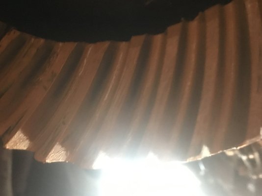
Also found out that both carrier bearings\races were a little thicker as well..........had to pull out another .012" to get the carrier bearing preload right (2 .006" shims.........had to pull out 2 .006" shims last year to get the carrier bearing preload right) so this put me in a corner as I didn't have enough thin shims left to really work the BL setting so the closest I could get to the .007"-.009" BL spec was .010" (move 1 shim inward would hit .003" BL) so I had to roll w\ .010" BL. Checked pattern as follows below:
This was still close to the initial pattern check prior tear down but was a little tighter towards the DS toe end of teeth than I wanted to be but the CS was looking pretty good, so I went w\ it. Finished buttoning all back up, loaded the diff w\ 2.5 qts of STP 85W-140 GL-5 dino fluid (local AZ has stopped carrying the Lucas HP 85W-140 GL-5 dino fluid, only the 80W-90 version) & ran it on the jackstands to check over prior actual test drive then stopped until this morning to put her on the ground & test drove car...............happy to report that this has now been resolved......no more 40-45 MPH resonance whine on decel anymore, can pick up a very faint hum when rolling in both accel\decel at speed w\ audio turned off that almost blends into the tire\road noise which is more than acceptable & IMHO is about as good as I'm gonna get w\ this Motive Gear F888390 3.91 actual 11 pinion\43 ring 5-cut face milled full hunting gear set running in this Ford 8.8" SRA axle.

Here is a YouTube video of the post bearing\race inspection on the Motive Gear Ford 8.8" install kit that was used when the Richmond EXCEL 3.90 gears were shop installed, then I reused them when I pulled them & replaced w\ the Motive F888390 3.90 gears:


You'll see that both carrier bearings\races were bad & the immediate cause of the resonance I was getting........so these also had a part to play w\ the Richmond EXCEL 3.90 gears (used same bearing\races on both sets of 3.90 gears) as well.

Lesson learned...................only use the Ford Performance M-4210-B2 8.8" Ring\Pinion install kit in these Ford 8.8" SRA axles & if you encounter any gear whine from gears, always change out the bearings\races w\ new stuff at the same time. I kinda knew this already, but I was wanting to reduce some costs & since these bearings\races were NIB & hadn't been in service for <1,500 mi, I overruled my common sense & reused them after I made initial visual inspection in which I don't remember seeing any of what I saw this time around........but the evidence isn't lying, the carrier bearing races were out of round & off pitch from the bearing rollers which can set up this type of resonance whine from carrier wobble upsetting the carrier-to-pinion angle alignment.

Finally, another issue now fully rectified. Next up is installing the Dynamat Xtreme sound deadener under rear seat\trunk area.........this should finish her up.

Midlife Crises, if you read this, what type of apparatus do you use to handle this axle when you R&R it during any diff work? I used my low-profile floor jack & got it handled, but there has to be a better tool suited for this.

Any info will be appreciated.

New .028 PD .010 BL 20 in lb Preload Coast Side.JPG

New .028 PD .010 BL 20 in lb Preload Drive Side.JPG
 
Last edited:

GriffX

Member
Joined
Sep 28, 2017
Posts
537
Reaction score
183
I had also an uneven worn out pinion race (the big one) at 30k miles. Why does this happen?

My set-up attached. Backlash 0.22-0.26 mm

vgl-0,65(0,22-26).JPG
 
Last edited:

GlassTop09

Senior Member
Joined
May 24, 2019
Posts
1,145
Reaction score
526
Location
Farmington, NM
I had also an uneven worn out pinion race (the big one) at 30k miles. Why does this happen?

My set-up attached. Backlash 0.22-0.26 mm

View attachment 89441
The only reasoning I can give for the uneven bearing roller to race wear pattern (especially the ones that I just pulled) is a badly machined\poorly matched\out of round bearing race that got thru QA\QC.
From observing product descriptions lately of various carrier\pinion bearings at various part stores (AZ, O'Reilly, NAPA, etc) I'm not seeing hardly any products labeled as a matched set anymore (meaning the bearings\races are sold as a complete package thus are presumed to be run-out\lapped so the inner bearing race, bearing rollers & outer bearing race are fully contacting each other & are true\not out of round) but are sold as separate parts made to a std OEM manufacturing design spec so different manuf's bearings (Timken, KoYo, ACDelco, Precision, etc) & races are "interchangeable" & can be used in different make\model axles.......also are somewhat cheaper as well when sold separately.

I noticed that even the ring\pinion install kit's bearings & races don't show any sign of being pre-run or lapped like they used to back in the day..............the main reason why I liked Timken bearings so much.........but this FP M-4210-B2 install kit's bearings\races that I bought were made by KoYo instead of Timken (all the bearings\races in the Motive Gear 8.8" Ring\Pinion install kit that I got to use w\ the Richmond EXCEL 3.90 gears were also made by KoYo) so will be interesting to see how these fare over time.
 

GriffX

Member
Joined
Sep 28, 2017
Posts
537
Reaction score
183
An other thing I noticed, when I measured the pinion bearing pre-load I had a mismatch between left and right turning of the pinion. I adjusted the resistance for the forward direction maybe that is the reason why I hear some whine on deceleration, after the noise insulation a LOT less :)
I haven't seen any advice what to do when you have this mismatch.
 

GlassTop09

Senior Member
Joined
May 24, 2019
Posts
1,145
Reaction score
526
Location
Farmington, NM
An other thing I noticed, when I measured the pinion bearing pre-load I had a mismatch between left and right turning of the pinion. I adjusted the resistance for the forward direction maybe that is the reason why I hear some whine on deceleration
This is new to me as I've always checked pinion bearing preload on drive side (forward) rotation of pinion gear............. From all the research I've done across the 'Net on a decel only gear whine, most all results data points back to a bearing\race issue as the most likely cause.........in the end its all subjective, though..........IMHO too many variables to account for, especially if someone else did the install\setup.
 

GlassTop09

Senior Member
Joined
May 24, 2019
Posts
1,145
Reaction score
526
Location
Farmington, NM
Now this makes all the sense of what the Spark Advance\Borderline Correction\VID Octane Adjust map is used for in this SO PCM......to correct spark timing (only when ALL 8 CYLS show spark timing cuts at the same time that drop below the base BKT\BKT VCT adder timing line.....thus PCM thinks fuel octane is the issue) by the amount as set in this map to the base BKT\BKT VCT adder timing line & run there ignoring the base MBT\MBT VCT timing.......then when KS activity shows all to have cleared back up, the PCM will return to all normally programmed spark advance timing scenarios automatically.
FYI.................

Been doing some research on this over time & have found that what I typed here concerning the VID Octane Adjust BKT Spark Advance Correction timing map in these SO PCMs is not exactly correct, so I'm giving a corrected explanation.

1st off, this function is a derivative of the old Ford Octane Adjust plug wiring socket used w\ the introduction of EEC PCM usage by Ford during the later MY Foxbody & all MY SN95\New Edge era (this allowed the PCM to add an extra programmed specific amount of spark advance timing to the base BKT spark advance timing table to compensate for using higher octane fuels than what the PCM BKT base timing map was originally tuned to run under or if the engine was experiencing some consistent knock\detonation from using some poor quality fuel, etc, to simply "unplug" the plug from this wiring socket thus will tell the PCM to retard the base BKT spark advance timing map settings by this same specified amount of spark advance timing to stop the knock\detonation to protect the engine until the cause of the knock\detonation is rectified, then the "plug" can be reinserted back into the socket thus the PCM will add this specified amount of spark advance timing back to the base BKT Spark Advance timing map settings). Thus, a manual way to "tune" for higher octane fuel usage or to provide additional engine protection against consistent\excessive cyl knock w\o having to access the PCM thru the OBD port\PCM chip........back in the day.

So, starting w\ the 05 MY, the SO PCM is programmed to do this Octane Adjust function fully within the PCM's OS coding once the Octane Function "plug" is set in the VID block (this tells the PCM the specific fuel octane AKI the knock sensor algorithms are trying to detect cyl knock thru the KS mic voltage signaling when they become active.......kinda like how the PCM uses LTFT to make A\F correction to maintain Lambda 1.0 during CL, except this is a static setting in all 05-10 MY SO PCM OSs.......except in 08-09 MY Bullit & '10 MY SO PCM OSs.....these have the additional coding enabled in OS firmware to use this same Octane Function plug setting dynamically thus can reset this VID block setting in KAM to "match up" the VID block Octane Function plug setting to the corrected base BKT spark timing retard as set up thru the VID Octane Adjust map settings under the BKT Spark Advance Correction heading at the specific engine load & RPM that stopped the cyl knock) that tells the PCM which specific fuel AKI modifiers (87, 89, 91, 93) to apply to the knock frequency filtering algorithms coding used to interpret the KS mic voltage signaling received by PCM after all frequency filtering settings\cyl noise threshold sensitivity filtering settings has been applied to indicate if cyl knock has occurred & the severity of said knock to then figure out how much spark retard amount to apply & the rate of application per process loop to try to stop the cyl knock from occurring.......until the cyl knock actually stops happening then the PCM will go into knock recovery to try to regain the lost base BKT spark advance timing\knock sensor added advance timing OR the max retard set amount of spark retard timing is reached (heaven forbid this happens)......whichever comes 1st.

The trigger that activates this VID Octane Adjust algorithm (is hard coded & runs in the background thus no direct access to it thru the calibration file) is whether the PCM is actively using either the IAT or ECT BKT Spark Advance Correction or not when the cyl knock is detected....if either\both of these is\are in use when the cyl knock is detected (the actual IAT or ECT is above\below the upper\lower 0* deadband spark correction settings), then the PCM interprets the cyl knock is caused by either high\low IAT or high\low ECT base BKT Spark Advance correction thus doesn't activate\apply the VID Octane Adjust algorithm. But if both the IAT and ECT are within their 0* deadband operational settings (no spark advance correction is being applied to base BKT spark advance timing map settings) when the cyl knock occurs, then the PCM interprets the cyl knock is due to fuel octane & will activate the Octane Adjust algorithm & only retard the base BKT Spark Advance map spark advance timing used by the amount of spark retard as set in the VID Octane Adjust map in the cell(s) in which the cyl knock occurred according to engine load & RPM at the time of the cyl knock detection (thus is stored in KAM). This is in addition to the amount of spark retard applied thru the knock sensor controlled spark advance\retard & will hold this in place until the cyl knock has stopped & the knock sensor spark advance has fully recovered it's retarded spark timing & the actual IAT\ECT is stable within the 0* deadband BKT IAT\ECT Spark Advance Correction (which indicates to the PCM that the fuel octane AKI is restored to\above the fuel Octane Function plug setting) at which time the PCM will restore the spark amount retarded from the base BKT Spark Advance timing map back to the current map settings (removes the correction from KAM), thus restoring all back to "normal".

Thus, this serves the original idea behind the usage of the early Ford Octane Adjust plug & wiring socket design......except this is fully automated within the SO PCM OS firmware now so no external physical wiring or activation plug is needed.

When all is tuned properly, this algorithm will very rarely be used (if at all) as the overwhelmingly vast majority of the time, most all cyl knock that happens is usually preceded by either the IAT or ECT BKT Spark Advance Correction (or both) being outside of their 0* deadband settings & being actively applied at the time of cyl knock occurrence, so PCM is not interpreting the detected cyl knock to be fuel octane related.......even if the detected cyl knock IS actually partially influenced by fuel octane (what normally happens\occurs when you're "riding the edge" of knock sensor sensitivity).........

Why most tuners just zero out this VID Octane Adjust map's settings (this is how to "disable" this octane adjust algorithm in the SO PCM OS thru the calibration file w\o having to go into the VID block).

Keep this in mind if\when going in & tuning the IAT\ECT BKT Spark Advance Correction & multi settings.......w\ this VID Octane Adjust map not zeroed out. This is only active & operational when the knock sensors themselves are active & being used by the PCM.

So, this function does actually work.............to a point......though can be somewhat erratic depending on how all the rest is tuned to operate.

The VID block Octane Function plug setting is important for the PCM to know what the fuel octane AKI rating is of the fuel that is being used to properly set the specific cyl knock detection frequency algorithm in the OS firmware that matches this fuel AKI rating for proper cyl knock detection in this SO PCM......the same reasoning applies as for setting the fuel stoich AFR setting in calibration to match the actual fuel stoich AFR of the fuel being burned in engine....thus should be physically set in PCM OS VID block to match (which in my PCM's OS VID block is verified physically set for 91 oct fuel thru using my now defunct HPTuners NGauge tuner to access the PCM OS VID block setting PIDs, thus BAMA did do something right).......unless you're lucky to have a 08-09 Bullit\10 GT (the Ford recommendation is to use premium fuel in these vehicle's engines but can use regular fuel as well w\o incurring engine damage due to the adaptive octane spark algorithm enabled in their PCM's specific ver OS).

FYI, I've had this active in my tune calibration file since around early March of this year & have only captured this algorithm actually working in 1 instance to date & it only held it for approx 2 1\2 secs when it did work while a datalog was running.......never felt it thru engine operations at all when it did kick in\release. Has never activated during any recorded OL WOT PE operations to date.......only knock sensor-controlled spark advance\retard from any WOT induced cyl knock until I found\properly fixed\tuned all the valid & false reasons\issues that was causing it..........the VID Octane Adjust BKT Spark Advance Correction wasn't 1 of them.

Note: the advent of me using the BKT Spark Advance VCT Adder Multi correction (adds additional spark advance timing to the base BKT spark advance map timing settings AND to the MBT equivalent which will equally affect the PCM Torque Management operation\application....from VCT cam degree retard operations in which the VID Octane Adjust map doesn't affect\influence is most likely a valid reason as to why I didn't feel this when it applied). Most tuners also zero out these maps to disable this VCT IVC dynamic compression correction algorithm.......IMHO, a mistake to do so but YMMV.

So, IMHO, I find this from actual testing to not be a big enough of a deal to disable it from operation in the grand scheme of things tuning-wise.........thus a YMMV subject (especially if actual extended racing usage is NOT the intended subject) & will leave it enabled\active in my optimized tune calibration file since I fully understand how this actually works now in these 05-10 MY SO PCMs.

The way I see it, it's just 1 more engine safety parameter operating in the background that is actually useful whenever it does kick in when needed.........such as from putting in some poor quality fuel in the tank.........

Just as Jeffery Evans @ Evans Performance Academy has also found & stated in his 05-10 Ford Mod Motor HPTuners tuning course.

Posted for informational purposes to those so inclined...............
 

GlassTop09

Senior Member
Joined
May 24, 2019
Posts
1,145
Reaction score
526
Location
Farmington, NM
FYI................

Concerning the usage of the CMCV's in the OEM 4.6L 3V IM, I found on another BBS forum topic dated in 2007 (the poster actually worked for Ford's SVT program at the time thus some insider info) that the IMRC BKT\MBT Spark Adder map settings were only actually used when the PCM IMRC control OPENED the CMCV's fully open thus flagging the PCM thru the IMRC actuator position & these CMCV's were NOT an incrementally operated control system......only a zero sum operation.......either fully open or fully closed (the IMRC Opening TQ % vs RPM map settings tells the PCM to open the CMCV's full open from full closed once the actual operational engine TQ load% exceeded the in map TQ load% setting at the specific engine RPM associated) so their existence is\was exclusively intended to be used fully closed during all idle thru most part throttle operations except for OL WOT PE operations w\o any extra additional BKT\MBT Spark Adders being used (even though IMRC Closed BKT\MBT Spark Adder maps are present using the exact same settings as in the IMRC Open BKT\MBT Spark Adder maps......PCM simply ignored these IMRC Closed BKT\MBT Spark Adder map settings when the IMRC control flagged the CMCV actuator position as fully closed) so the science behind why their existence is the only reason (to overcome the 3V cyl head's poor intake port A\F mixing characteristics by inducing increased airflow velocity thru 1 side of open intake valve port during the intake stroke at low RPM operations to induce tumble inside of the cylinder head chamber to further improve A\F mixing to achieve optimum A\F mix along w\ any intentionally reversed exhaust gases--EGR thru VCT induced cam retard timing as far as can be retarded to reduce pumping losses & at the same time not reduce the necessary calc'd engine TQ necessary thru TM to maintain the desired TM DD TQ Request from ETC APP throttle control at any engine RPM during part throttle operation under CL--thus maximize engine TQ output during part throttle operation while also reducing overall emissions output--notably NOx emissions thru EGR usage & improving MPG as well thru EGR usage by reducing the amount of fuel to use from reduced % of fresh airmass entry from EGR exhaust occupying some % of the total usable dynamic cyl volume available). The OEM settings were set up for all this to be fully open & all IMRC Open BKT\MBT Spark Adder Correction map settings applied by 4,100 RPM's while the ETC had TB fully open & OL WOT PE operations were operational (thus why the "camel humped" TQ curves drawn on dyno sheets during WOT from 2,500 RPM's thru 5,000 RPM's when these CMCV's were operational).

Now from finding & reading thru this now, I'm initially tempted to pull my '08 OEM IM, remove the Steeda CMDP's & reinstall the fully functional OEM '08 CMCV's & IMRC actuator assembly that came w\ the IM (saved them intact for this very purpose if necessary) then go in tune calibration & reset the IMRC Opening TQ % vs RPM map settings back to OEM settings then test this out w\ my tune calibration as currently set up (all IMRC Open\Closed map settings in my tune calibration file are identical thus no changes will be made to any tune settings from an open\closed CMCV instructing the PCM to switch IMRC maps & the particular IMRC Open\Closed BKT\MBT Spark Adder Correction maps are zeroed out thus disabled so no "extra" spark advance timing application from either of these to further muddy the waters, so to speak) as this will\should prove\deny the science behind their design\usage outright.

As long as the fuel inj EOIT CA setting in tune file is correctly configured to match the cam's adv dur IVO timing point (from my tuning this setting is a HUGE factor in optimum A\F atomization\mixing from initial swirl from ending spraying of fuel on the back of hot intake valves just at the point of opening during valve OL taking advantage of exhaust scavenging velocity from exhaust-to-intake transition), I can see these providing a small amount of improved low RPM TQ output in NA configuration.....if at all......vs them not being used thus the science is justified, but the big question for us enthusiasts is whether the perceived\measured low\mid RPM TQ improvement from their use can actually be FELT & not just simply measured while the CMCV's are closed (like the dyno showing a 2 HP, 2 TQ peak gain measured but in actual operation can't be felt\detected thru the butt dyno). So, I'll assume that the more measurable improvement will\should be MPG & emissions.......but from seeing my actual recorded operational Cat CE Ratio numbers w\ CMDP's installed, I can't see the emissions getting any better & an outside chance they actually get worse as well as any measurable MPG gains will also be small if at all, again based on the current actual recorded MPG of 21.5 MPG under current tuning setup\vehicle configuration......haven't driven the car long enough on any sustained mileage trips ATM to fully flesh the calc'd MPG out to max so until this is achieved prior experiment initiation, the perceived results are IMHO pretty meaningless.

But there's only 1 way to find this out for myself & that is to do it & fully test this out..........but at this time I really just don't have the inclination to go thru w\ it due to the current results I'm currently seeing\getting w\o their use.

Maybe 1 day in the future when\if I get totally bored & need something to do to fill in the boredom..................don't hold your breath hoping for this to happen soon though.......you may need to inhale. ;)

Posted for informational purposes for those so inclined.............
 

GlassTop09

Senior Member
Joined
May 24, 2019
Posts
1,145
Reaction score
526
Location
Farmington, NM
On the tuning front................

I've been going back thru a lot of my recorded datalogs looking at them to see if I can detect any signs of some extra advantages I've missed during my early tuning "career" (also to pass some time during late evenings\nights while listening to some music thru my headphones before going to bed) & I've found another thing that I intended to do but got lost during my active tuning........I forgot to set up in VCM Scanner datalog\histogram graphs all the TQ Management TQ channels (Sch TQ Req, EI TQ Ref, ETC TQ Req, Des TQ......already had EBTQ set up in all histogram\datalog graphs to use the "Dyno" graph in VCM Scanner.......had already set all these channels up in my master VCM Scanner channel list file but forgot to set them up later in the graphs) to then use them to accurately model the VCT load mapping\BKT & MBT VCT Spark Multi Adder maps thus are modeling the cam to crank correlation thru VCT to achieve the max TQ output across the widest area of the TQ curve as possible\feasible (I used my understanding of the cross-plane crankshaft design to match up the cam-crank correlation using math......remember me posting all this earlier in this thread as shown below?). So, after getting all this done in the specific chart where I also have VCT setup along with the base BKT\MBT Spark Advance maps & BKT\MBT VCT Spark Multi Adder Correction maps (thru which all engine TQ output is controlled thru TQ Management......note the channel called ETC TQ Req.....this is how TQ Management uses Ford's vers of speed density thru using the LWFM MAF map in this SO ECU--not the MAF--to calc & initially apply the engine TQ needed according to engine load & RPM proactively to apply to the crankshaft. As I've said earlier, the MAF is used as the ECU's reactive sanity check to the ETC SD TQ airmass control proactive calcs so in reality, your engine will operate as well--or as bad--as the ETC SD TQ control is set up in the tune calibration......including the TB's PTA\EA mapping in tune calibration.......more on this later......as long as MAF Adaption is enabled so the ECU can correct any deficiencies found in the MAF\LWFM airmass calibrations\calcs.....is what the STFT+LTFT fueling corrections from O2 sensor feedback away from 0% are in general exposing as long as the fuel injectors, fuel injector data & FP operations are good & accurate).

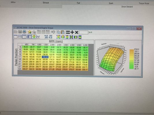
So once I got all this set up in all the VCM Scanner histograms\datalog graphs that I use, I now can see the already recorded TQ Management channel data in my datalogs along w\ all the rest in real time.........the very 1st thing I saw in all my datalogs was TQ Management was vastly over calc'ing TQ output under high load operations (includes WOT) & since I've already verified that all the TQ Management mapping in ECU was still OEM mapping (by default, the Ford tuned TQ engine mapping is tuned to output as high as 400 lb-ft+ of engine TQ by itself, thus in NA config there is no reason to touch any of this mapping.....even in stroked NA config) so this left only 1 area where this is occurring.....the TQ Management DD TQ Request mapping or "pedal TQ mapping" (in the ECU channels it's called "Sch TQ Req".......so I've now ID'd how other tuners who either don't know how to recharacterize the TB in tune PTA\EA maps to fit a larger installed TB or are too lazy to do it so TQ Management can properly\accurately calc engine TQ output using it. What other tuners are doing to get around using a 62mm TB w\ the OEM 55mm TB's in-tune PTA\EA map calibration is intentionally increasing the "pedal TQ map" settings, especially in the 327 & 545 A\D count rows where high load\WOT TQ requests come from to "offset" the now inaccurate TB PTA\EA mapping in tune to force TQ management to "make up" for this so actual engine TQ output won't get cut short.

This finding verifies what I posted in this thread some time back concerning this tuning mismatch potentially throwing off WOT calcs tune wise if not addressed.

In my case, since I've properly corrected the PTA\EA in-tune mapping to correctly fit my FP 62mm TB's physical butterfly OD\housing ID area but wasn't aware of this tuning patch work, TQ Management in my tune calibration was grossly over calc'ing TQ outputs as high as 527 ft-lbs+ thru Sch TQ Req map data w\ EI TQ Ref concurring it (both graphed over each other.....this calc doesn't account for internal friction or accessory drive TQ losses) & ETC TQ Req was then over calc'ing TQ output as high as 467 lb-ft+ w\ Des TQ (the MAF sanity check I mentioned earlier.....these do account for internal friction & accessory drive TQ losses thus why the gap between them on a graph...the higher in RPM the engine spins this gap grows wider for obvious reasons) concurring the ETC SD TQ calc's but the EBTQ (actual calc'd engine TQ output to crankshaft) was only at 207 ft-lbs TQ range......due to the patchwork TB PTA\EA correction tuning not known to exist & would've never known.........if I hadn't gone back & finished setting up the rest of the TQ Management channels in my VCM Scanner histogram\datalog graphs & rechecked all my datalogs. The key for me to catch this is seeing just how wide the TQ gap was between the 2 TQ control systems when I know the ECU is turning the AC compressor off during high load, WOT ops so I knew something was off in the tune file & the only map that wasn't OEM anymore was the TM DD TQ Request map & the target area in this map was the 327 to 545 A\D count rows where all high load\WOT TQ requests come from (remember back earlier I had reworked this map in the low end from the 16 thru 92 A\D count rows to improve low end response thru the APP but left the rest as found only applying 3D Smoothing to the entire map after rework). Didn't have to take out much TQ to fix this.....only cut the 327 line across the whole row by 20 ft-lbs & the 545 line across the whole row by 40 ft-lbs to bring all back into some type of respectable correction......now the gap is reduced to a more respectable 30 ft-lbs to 68 ft-lbs gap across full engine RPM operating range (makes far more sense than the 60 lb-ft+ for internal engine friction\accessory drive TQ losses......have seen this go over 100 ft-lbs in some instances which is insane.....water pump, alternator & PS pump don't nearly eat up this much TQ....ECU cuts alternator charging off during this same time as it does for the AC compressor & if PS is held in straight forward position the PS pump assist output press is dithered across the rack thus is also very low so not much load on engine) & better yet, I noticed the whole map shift & realign itself (settings realigning to the underlying map X-Y axis scaling according to the already applied 3D smoothing due to me making uniform changes across the entire Y-axis rows thus not upsetting this within the map) so I felt good about finding this "patch" & fixing it.

Now I turned my attention to this graphing to make checks to my camshaft modeling in VCT to ensure that I'm getting the most crankshaft TQ output. I noticed that during WOT, as engine RPM's increased my EBTQ was slowly decreasing even when the MAF was showing increased flow......indicating that my VCT load map & BKT\MBT Spark Advanced Multi Adder map settings weren't optimized especially at the upper end & also during high load low RPM operations (like climbing up steep inclines while in 5th gear). Both times when this was occurring, I saw the ECU advance the cam timing during high load low RPM below 12* retard (which improves IVC dynamic compression--cyl pressure--but cuts EVO power leverage at crankshaft (stopped the usage of 2 cyls applying force to crankshaft at the same time....my Lunati cams adv dur EVO cam timing needs to be at 15* retard minimum to hit the 1st graph below) forcing engine to exceed cyl temps of E10 91 oct fuel's AKI rating causing engine knock to appear (was at 29* total timing) further cutting TQ output. At WOT loads, the 15* retard wasn't providing enough EVO leverage to maintain TQ output as engine RPM's went up, also putting more strain on cyl pressure causing the cyl temps to exceed the fuel AKI rating again inducing knock (also occurring at 28.5* total timing after properly fixing the knock control mic to cyl assignment between #2 & #6 cyls to straighten out the ECU's cyl noise sensitivity threshold interpretations across the engine firing order). In all the rest of the datalogs, when the VCT had my cams retarded well past 15* retard (in the 20*-30* range)....even at low RPM's, all EBTQ output mirrored the ETC TQ Req graph lines w\o any hint of cyl knock.....only the occassional false knock created by the ECU operating the VCT solenoids whenever the ECU called for a VCT cam timing change in response to TQ Management calcs at the same time the ECU also is enabling the knock sensors (you'd be surprised at just how loud these VCT solenoids can get when the ECU dithers the VCT solenoid valving under operational EOP.....both KS mic voltages can jump as high as 20mv-30mv over baseline KS mic voltage signaling off normal engine generated noise thus ECU can falsely interpret this as cyl knock & cut spark timing....even at loads as low as .25--right off idle--where no cyl knock can exist due to cyl pressure being far too low to generate enough heat to self-combust the A\F mix)!
Most usually say this is due to outside components (like exhaust) hitting the unibody, which can be true......but I've seen\witnessed that this is more related to the VCT solenoid operation than any exhaust rattling on my car (I have Pypes Super Bomb Mid Muffler catback exhaust installed along w\ Kooks LTH's & midpipe so she can get very "resonate" at times but is also verified to clear all unibody except for where I have 2 exhaust hangers off mid pipe attached to the cross member bolts & the OEM exhaust hangers at the rear of the car) as the datalog graphs prove this out in spades. It is this issue I now believe is 1 of the reasons why Ford set up knock retard in OEM tune calibrations to use Global Mode instead of Per Cyl Mode to use the filtering frequency signal up\down avg'ing when accel\decel vs not accel\decel to overcome the VCT solenoid sound frequencies affecting the KS mics voltage signaling (reenabled Global Mode in my tune file to test this out & saw this VCT solenoid interference reduce quite dramatically....still gets thru every once in a while but not near as frequent.....was very bad during 1st gear take off only.....from 2nd gear on, no issue. Now it is mostly cleaned up under Global Mode to the point that the little it does show thru makes hardly any noticeable change in spark timing advancment.......can still see it but the ECU rarely responds negatively to it).

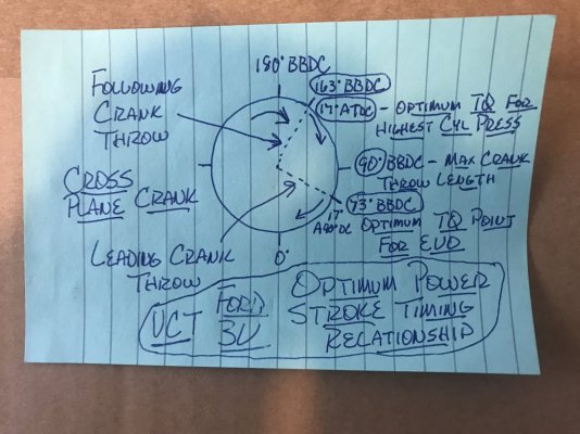
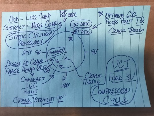
So then I put my drawings to the test & reset my Airload VCT load map settings from 50 load thru full on WOT to retard the cams around the 20* retard area or higher as I deemed fit to ensure that the power stroke side was effectively using 2 cyls force during a single power stroke event for at least 5* or more past the 15* threshold (the 73* BBDC I show in drawing that gives a smooth TQ handoff from leading cyl to following cyl w\o needing to use the flywheel inertia to continue crankshaft rotation....this also reduces some pumping loss as well thus also frees up some more net TQ output) based off my Lunati cam's adv dur EVO timing point then readjusting the BKT\MBT VCT Spark Advance Multi Adder map settings in the same load rows to offset the dynamic IVC compression loss to stabilize\optimize the operational cyl pressure during compression stroke\ignition firing cycle (what the end result is trying to achieve.....max cyl pressure buildup on piston just as the piston is starting to move down the cyl bore at the 17* ATDC crank throw point of the power stroke but stay under the structural capacity of the cyl heads\cyl head bolts & piston\con rods at the same time) to keep as much cyl pressure I can w\o causing excessive enough cyl temp to set off detonation (or cyl knock).

Subsequent datalogs show that this does indeed work as designed......engine EBTQ stabilized & slightly increased w\ a clean knock sensor output across rising engine RPM's at the same total timing settings so I could now actually increase the base BKT spark advance timing & get some more TQ out of her......w\o needing to artificially "doctor" any of the TQ Management control mapping (so actually tuning the cams to crankshaft to get max net TQ output to drive train or to "match up" to the ETC SD TQ Req calcs as best I can).

Was able to now almost get to 31* of total spark advance timing w\o cyl knock occurring at WOT (was looking very good until I hit 4th gear.....the engine loads just got too high for the E10 91 oct fuel's AKI rating @ 31* total timing so the higher cyl pressure put out just enough extra heat to start causing sporadic cyl knock.....even w\ OL fuel A\F at 11.835:1 actual (figured out how to use the MAF airmass lbs\min calcs along w\ the FP fuel output flow rate in lbs\min to get the actual A\F equivalent to then back check the ECU EQ Ratio Lambda calcs using the fuel stoich AFR of 14.08 @ Lambda .82--the OEM Ford-set OL Lambda WOT fuel setting, FYI--as set in my tune file for OL WOT fueling w\o using a WB O2 sensor......which comes out to 11.5456:1 A\F so OL fueling is very close (calcs out to be only 2% difference) & is set very well thus the actual fuel's AKI is the issue at this point (WOT IAT was @ 73*F & ECT was @ 203*F so my Mishimoto HP Aluminum rad\Ford GT500 cooling fan w\ the hi speed trap doors in the shroud combo & Ford OEM Bullitt 83mm "sealed" CAI w\ K&N filter was carrying the mail just fine).........every time cyl knock showed up, the extra fueling was trying to cool her right back down so the ECU was in constant motion to initially back off then readvance the spark timing back towards the MBT Spark Advance graph line as the SO ECU's OS is coded to do to self-optimize TQ output.....most it ever dropped at any time during the 4th gear WOT hit was between .5* thru 1.8* off the full 4* of knock sensor spark timing max advance (thus well above the base BKT spark advance "floor" timing so ECU was in complete control of all of this & not hindered in any way) w\ the 1 instance of a 3* spark retard as shown in the VID Octane Adjust map so I then checked the engine operational IAT\ECT to see where they were at.......I found both to be within their 0* deadband settings at the time of the 3* spark retard thus is another instance where I've witnessed this SO ECU apply the Octane Adjust algorithm as I explained in another earlier posting in this thread due to it interpreting the cyl knock as octane related (which it was). Once this was applied the cyl knock stopped showing up completely so the ECU went into full spark recovery mode to regain the lost spark timing when I let up & got out of WOT. Checked the EBTQ graphs.......drew a straight line across all WOT gear hits w\o dropping off.....either level or slightly rising along w\ the rising MAF lbs\min & RPM's graph lines so she's as optimized as I can get her on the street w\ these Lunati VooDoo #21270700 cams installed using E10 91 oct fuel. Will need to strap her on a dyno to use the dyno TQ calcs to back check my ECU calibration's TQ calcs to see how accurate all lines up for shits & giggles. I think the EBTQ TQ is a HPTuners VCM Scanner calc

The highest spark timing I could now use w\o cyl knock was 30* so I split the difference & set her at 30.5* total timing but it got too dark to datalog her so I shut it down & will datalog her during the next drive cycle to prove out all IM Readiness checks to see if she'll stay calm......if she does then I'm finally done w\ all the street\remote tuning as I KNOW now that all is now fully correct & set up properly in my tune calibration & all is working as it was intended to.......including all engine safeties are now fully active in tune file as well & not neutered so they'll get my engine out of any trouble fairly easy when they need to do so.....outside of basic structural deficiencies from simple structural fatigue over time.....which is all 1 can ask for.

Posted for informational purposes.
Ford 4.6L 3V VCT Optimum Power Stroke Timing Relationship.JPG

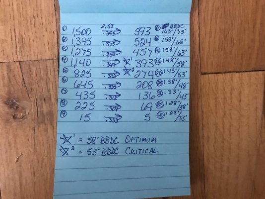
Ford 4.6L V8 Optimum Power Stroke Cyl Press Using 90 Degree Crank Lead Follow Cylinders.JPG

Ford 4.6L 3V VCT Intake Dynamic Compression Cycle.JPG
 

GlassTop09

Senior Member
Joined
May 24, 2019
Posts
1,145
Reaction score
526
Location
Farmington, NM
FYI.......................

I got to thinking about TM some more this morning so I went back & pulled up Jeffery Evans @ EPA Ford 05-10 Mod Motor HPTuners training videos & refreshed myself on tuning the Torque Management system in these SO ECUs & Jeffery stated that if tuning the TM DD TQ Request Map settings for a NA config 4.6L V8 to 1st leave it in stock settings & only raise the 545 A\D count row settings (what ECU uses for WOT TQ requests) approx 100 ft-lbs to give enough room to do all your tuning w\o potentially getting clipped in the process. He also stated to leave the rest of these settings in this map alone until you've fully finished everything else then to come back to this map to do any final TQ request tuning to dial in the "pedal feel" to your tastes (so TM Control has all the other aspects in the tune calibration correct that it will be relying on to do its job). Then based on the final data, you can then edit the 545 row settings to match up to the final EBTQ (engine brake TQ) graph settings if desired to finish up.

So according to Jeff, this TM DD TQ Request map should be the very last item you should be touching to finish out a tune calibration.

After watching\listening to this, it was clear now that in order to properly correct the TQ Management modeling so that all is in full agreement I was gonna need to ditch the BAMA\prior tuner touched TM DD TQ Request map in my tune calibration & reload the OEM '09 MY stock vers & redo all this myself, so I did just this then went into the 545 A\D count row & upped the entire row settings by 60 ft-lbs (this put the settings on par w\ the 545 A\D counts row settings in the old map that I redid in last revision to try to fix this) then I highlighted the rest of the map settings (16 thru 327 A\D count entire rows) & raised them by 11 ft-lbs (to bring the low end area in some proximity to the low end rework I also did to the old map last yr). By resetting the entire row settings by the same amount of change, this maintains the underlying X-Y axis scaling of the stock map while evenly increasing the existing settings. After doing all this I then highlighted the entire map settings & applied the full 3D Smoothing to it to smooth it out. Then I went back to both my base BKT & MBT Spark Advance timing maps & cut the .70-.90 load rows (WOT) that I had cut earlier by .50* from the 31* total timing that caused cyl knock the other .50* to put all this back to the 30* total timing that I knew the engine could handle to be done w\ this part as I was hoping that my slightly tweaked OEM '09 MY Ford-tuned "stockish" TM DD TQ Request mapping would fix the TM modeling & bring all back in line (since the rest of the TM control mapping was still OEM '09 MY Ford-tuned mapping), saved all & flashed..............

Now this should also test my TB recharacterization PTA\EA map tuning to correctly model the FP 62mm TB in the ETC Throttle Control so the ETC SD TQ Req should now closely match up to\track with the EBTQ TQ output across the board in VCM Scanner........if I did this right.

Took her thru my 37mi datalogging\drive cycle route to run datalog & feel her out..........

All felt really good on the drive, engine response thru the APP felt pretty much the same thruout the drive as it did prior this revision, but I also did notice I had to be a little more selective of what gear I was in at low RPM\low MPH or the engine would momentarily be slightly sluggish then respond.........otherwise the acceleration felt the same as before. Otherwise, all else was good.

Got back home & saved datalog & after running the IM Readiness monitors (all completed on initial DC) I checked the logs.............

Success!!!!

Saw that TM had rescaled to now match up w\ EBTQ output pretty much across the board! So, the old BAMA-created TM DD TQ Request map (base tune file my prior tuner used to initially tune my car with was a BAMA 91oct Race tune I had loaded in to see how it would do while I was burning all the 87 oct fuel out of the tank to then fill up w\ 91 oct fuel then get it all thru the fuel rails so the car would be ready for the tuner to do his tuning as tuner requested that I put 91 oct fuel in prior tuning back in August 2018......) was throwing TM Control WAY OFF!

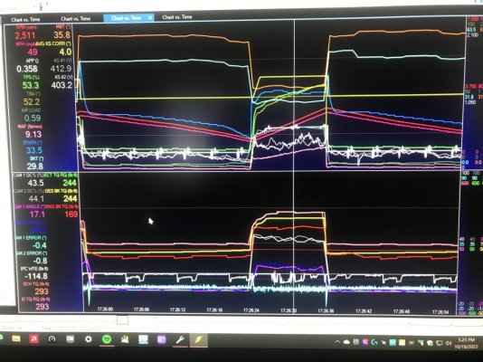
The data tracking is dang near on point now. ETC TQ Request graph is now lining up in very good agreement w\ the EBTQ output........so this result does indicate that I did the TB retuning properly AND you can clearly SEE TM actually doing its thing when car was put under a high load in 4th gear to maintain the ETC TQ Req to the EBTQ.......provided below.

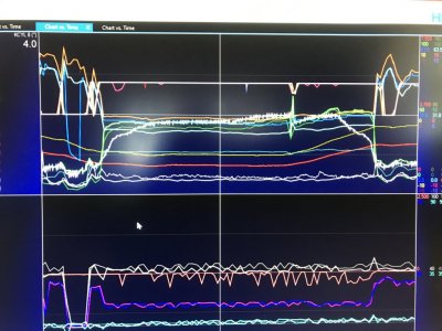
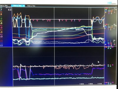
The bottom section of both pictures show all the TM control graphing along w\ the VCT control mapping, the upper section shows the base BKT\MBT Spark Advance & Current Spark Advance timing, APP, TB TPS%, TB TBA*, RPM, MPH, LOAD%, MAF, Global KR Spark Advance & #1\#2 KS mic voltage. Both pictures are off datalogs at the same area\section of road, in the same gear, driven in the same manner to try to show apples-to apples comparison between the BAMA influenced TM DD TQ Request map settings vs my new tweaked '09 OEM Stock TM DD Request map settings on the same '09 OEM TM Control mapping used in both tune revisions.

The picture showing the red graph line in bottom section is the 1 using the BAMA TM DD Request Map thus is showing just how far it was off. The other picture is using the new tweaked OEM stock TM DD Request Map.......you can see just how well all this is lining up now AND how TM is supposed to operate to maintain a ETC TQ Req.....see how the ECU TM system is working the TB separate from the APP to constantly make airmass adjustments along w\ base BKT Spark Advance timing while the KS Spark Advance was held at 4* max advance to maintain the TQ requested while the APP graph trace (the white line w\ indentures) is held constant (note how the ECU TM responded to the AC compressor cycling on\off thru TB to maintain the TQ req while under load). MAF (the pink graph line in upper section) is showing to be on the same track in both pictures but notice the MAF trace under proper TM control actually flattened out & started tracking parallel w\ the ETC TQ Req & EBTQ output traces.......indicating that TM has reached the target EBTQ output.......while the other picture is showing TM to try to push engine to reach a target that it can never attain.....evidenced by the ETC TQ Req trace being locked artifically above the red EBTQ trace & TB TPS% & TB TBA* traces tracking w\ the RPM & MPH traces.

Note that in both pictures, the EBTQ output is practically the same......but 1 picture gives impression thru OEM TM control using off base DD TQ Req mapping\tuning that the engine is falsely underpowered using the set VCT cam retard timing while the other 1 gives impression thru the same OEM TM control using proper OEM Ford-based mapping\tuning that is in line w\ the rest of the OEM TM control mapping that the engine power output is pretty much on point based off the same set VCT cam retard timing.

So, you see why I was trying to rectify this........w\o TM Control working properly it is hard to determine if engine is properly optimized outside of using a dyno.......but w\ TM Control properly setup\operating, the engine can be optimally tuned on the street as TM can show you when you're in the ballpark & when you're not.......as long as the EBTQ trace tracks in lock step w\ the ETC TQ Req control & all other graphed data is showing to be good & in line, this is telling you that all is good & there might be a little more to get out of the engine but the moment when 1 or more of the other data graph lines starts deviating from their tracking patterns (like the MAF graph line for starters) & the ECT TQ Req graph line starts climbing away from the EBTQ graph line & TB TPS%\TB TBA* starts climbing up towards their full open position, then the TM Control is indicating that the engine has reached its optimum TQ output based on the set VCT cam retard timing according to load% & RPM.....as long as the KR is not showing any cyl knock, or you have an issue showing up that is causing the engine to drop power (usually the VCM Scanner graphs will expose the culprit IF you have all the needed channels set up in the Channel file & all set up in the Datalog\Histogram graphs thus can easily take care of it...........

From what I'm seeing now, my new TM DD TQ Request map settings are pretty much spot on & I now think that it was TM Control kicking in at low RPM, low MPH due to ECU looking at the transmission gear position along w\ the gear ratio, revs per mi & N\V off VSS sensor to calc gear TQ then calc the necessary engine TQ to reach the ETC TQ Req TQ calcs using the Sch TQ Req\EI TQ Ref to get the EBTQ output to match up so I'll need to readjust my gear selection choices to be more in line w\ TM Control so engine will respond immediately going forward.

Gonna leave all as set for a while to give a good evaluation (along w\ a few future datalogs to run) of where the tuning is shaking out.

PS edit @ 10-20-23--after further checking of datalog, I found some cyl knock happening during a rolling throttle stab into WOT in between the .60 & .70 load rows around 4,102-4,524 RPM's halfway in to 3rd gear pull then again at the end of 4th gear pull (was still carrying 31* total timing in this area of the maps just before the ECU went into WOT PE enabled OL fueling to then get into the .70 load & up rows where the total timing would've been between 29.93* to 30.1* thus the ECU was still in CL @ 1.0 Lambda fueling--which was the cause of the cyl knock occurring.......took .75* timing out across the entire .60 load row in both base BKT & MBT spark advance maps in my next revision to fix this) so will be flashing revision in AM..........hopefully the last 1 as all else looked very good since resolving the issues w\ Torque Management in my tune calibration.

If subsequent datalogs show all to be clean going forward, I just might be able to call her done this time around.

In hindsight I wish I'd have caught this & resolved it much sooner........would've helped out tremendously & speeded all this up.

I know now......................

TQ Management Operation with Bad TM DD Request Map under High Load in 4th Gear.JPG

TQ Management Operation with Stock TM DD Request Map under High Load in 4th Gear.JPG
 
Last edited:

GlassTop09

Senior Member
Joined
May 24, 2019
Posts
1,145
Reaction score
526
Location
Farmington, NM
All right folks.....................

Got the latest revision flashed in ECU this morning (cut .75* of total timing out of base BKT\MBT spark timing maps across the .60 load row to lower total timing here from 31* to 30.3* to gently slope this timing from CL-NM transitioning into full OL WOT PE total timing of 30* across the ECU transition from the .50 load row, across the .60 load row into the .70 & up load rows (where the APP will have crossed the 545 A\D count row to end WOT transition w\ TB at full open TPS% & TBA*, kick OL Fuel Control into service, shut down the O2 sensors, shut down EVAP & go into full OL WOT PE spark timing control areas).

Ran car on my std 37 mi drive cycle route while datalogging.........all went flawlessly & car felt very good across the board (have gotten used to TM operations now so am making much better gear selection choices to set the proper gear\drivetrain mechanical TQ areas (make full use of them Motive Gear F888390 3.91 actual gear ratio 11 pinion\43 ring gears on my Conti Extreme Contact DWS06 295\35\18 tires @ 26.1" dia) to aid TM in optimizing the engine TQ output immediately so car is very responsive but also is increditably smooth doing it.........a main strength of using TM properly to control engine TQ output (not neuter it so the 3V acts like a 2V).

Got back home & checked logs............I can now say w\ assurance that my engine is now fully tuned out & optimized as good as I can get her on the street.......got a clean slate across the board (outside of the random false knock created by the VCT solenoids making high noise when ECU is dithering them to control or move the cam timing around & then hold them in position........mostly occurs during part throttle when VCT is constantly swinging the cams) & the EBTQ output under WOT is held on a flat trajectory thus not excessively dropping off while the ETC TQ Req graph line pulled up & away from the EBTQ graph line (so this will ensure engine to make max peak HP) while the MAF is on a steady incline trajectory as RPM's were increasing, verifying this.......all w\o cyl knock occurring on E10 91 oct fuel @ 30* total timing @ 11.803:1 actual AFR w\ VCT retarding the Lunati VooDoo #21270700 cams to 20* EVO retard so as 1st Officer Scotty has said to Capt. Kirk on many an occasion.......

"You're getting all she's got, Capt'n!
I've FINALLY chopped this tree down! :) Now to go cut some firewood! :driver:

Now when I pulled up the Mode 6 IM Readiness data (remembered to bring my OBDEX interface w\ me to then pull up Forscan to check\record all this), saw all monitors completed except EVAP on this run (but will quickly complete on the next drive cycle) & I finally saw what will happen when TM is in control & operating engine at full safe capacity........the Cat CE Ratio test results spiked up from coming in around .0xx on 1st run to now around the .1xx area (B1 @ .156, B2 @ .141 vs ECU set EPA legal threshold of .656 for both B1 & B2), which is still stellar for these MF #5461336 CARB-cert EO#D-193-140 TWC OEM-grade aftermarket cats at 84%-90% measured engine VE........bodes very well for all the non EPA-certified engine components I chose to run.

A properly tuned\setup TM DD TQ Request map data that allows TM Control to properly manage engine TQ output is paramount to doing good street\remote tuning on these Ford Mod Motor 3V VCT-equipped engines thru a Spanish Oaks ECU........period. Without it, you're flying blind on peak HP\TQ output & giving up good drivability in the process.......w\o being on a dyno.

Good thing for me is that from this day forth, it won't take me NEAR as long to do this on my potential future build or on any changes made to current engine from component changes (like cams.......).

I've also set up another copy of this same final tune calibration to properly use the OEM Ford 55mm TB w\ OEM Ford-tuned PTA\EA mapping from a 08-09 Bullitt calibration (little spicier than the OEM 55mm TB mapping for a std GT........how the Bullitt gets its 315HP, 325TQ FW rating) in case my FP 62mm TB potentially craps out on me (still have my fully operational 14 yr old+ OEM Ford 55mm TB in storage if\when needed).

In closing, if you want to get into tuning these Fords, HPTuners MPVI3 is a good option to consider & Jeffery Evans @ Evans Performance Academy's 05-10 Ford Mod Motor HPTuners training videos are an excellent resource to have to fall back on as well as Jeffery Evans himself thru his web site forums.

Been a LONG but very FUN ride!
 

GlassTop09

Senior Member
Joined
May 24, 2019
Posts
1,145
Reaction score
526
Location
Farmington, NM
FYI..................

As a last item of interest to note, I have also finally deciphered the cause of the random false knock I was seeing in my datalogs (also what my prior tuner was seeing but I'm not sure that he knew the cause so he most likely just somehow "disabled" them in tune calibration (have yet to figure out how he got the ECU to go into an "OL-not ready status"--like engine was still in cold start procedure--during WOT thru the calibration file so the knock sensors were temporarily disabled & will assume that he was using something like Tuner Nerd to back check the engine for cyl knock or have done enough of these to have a good sense of where to stop w\ spark timing advance.......like watching the exhaust for any signs of brown "dust" puffs coming out exhaust--signs of detonation present in engine--to know when to back off.....while car was on the rollers).

It's not the exhaust causing it (even though I have a total of 4 hangers installed & rest is clearing the unibody) & it definitely isn't the cylinders (operational cyl pressures are too low the majority of the time for any detonation to occur running E10 91 oct fuel..........

The cause is...........wait for it..............the VCT system (VCT solenoids & cam phasers) whenever the ECU is actuating the VCT system to position the cams at the same time the ECU is also enabling the knock sensors AND rarely when the engine is under a load & the ECU repositions the cams thru VCT!

Note: Since making the KS mic-to cyl assignment change between #2 & #6 cyls to even out the cyl knock threshold noise floor (the level of sound frequency a knock sensor can record thru metal is mostly determined by 1. the intensity of the sound itself at the source & 2. the distance between the sound source & the recording instrument picking it up as sound frequency will degrade over the length of travel thru any medium due to normal "scrubbing" effect of the energy--intensity--of the sound frequency travelling thru it, depending on the density, compressibility & the shear factor of a solid medium (like aluminum alloy) the sound frequency is travelling thru.

Physics 101.....................

In short, the assignment of a KS mic to the same leading\following cyl pairing according to engine's 90* firing order (cross plane crankshaft design) will cause the KS mic to record 2 different sound frequency signal levels (which they normally do anyway.....both KS mics respond to any engine or outside engine created sound frequency according to the intensity of the sound & buffered by the distance between the sound source & KS mic) in quick successive order to the trailing cyl due to trailing cyl being much closer to the KS mic than the leading cyl (experiences a much greater sound intensity frequency from the trailing cyl than the leading cyl (or the inverse of this).....even though both cyls may put out the exact same initial sound source intensity frequency) thus will cause a natural "spike" in the noise floor relative to the rest of the cylinders exceeding the relative engine noise "sound floor" so ECU records it as a cyl knock if this can't be filtered out by the knock control filtering algorithm settings set to determine the engine's "normal cyl noise floor"......even if cyl isn't actually knocking......thus cause the ECU to excessively cut spark advance timing for essentially no reason. Using Global Mode is masking this AND is applying the inflated knock detected signal on a global basis across all 8 cyls, further providing even more inflated engine protection......... At least the Ford engineers DID design\code the SO OS's to always try to add spark timing back after a cyl knock occurred then stopped. to make up for this back-sided coding "trick" to ensure engine safety for warranty purposes.

I originally thought this was a mistake by Ford engineers........but in hindsight I now think this was done deliberately to "code in" more engine knock protection than necessary for warranty purposes that was meant to be "hidden" in the code.........thus profit protection.

Ok now back on the subject at hand.....................

Since correcting the Ford induced KS mic -to-cyl assignment issue above, this levelled out the normal cyl\engine running noise floor to the point that other noise creating components are now exceeding this new lower noise floor.......such as the VCT solenoids & cam phasers.......VCT solenoids when the ECU starts sending commands to the VCT solenoid windings causing noise when these solenoids are being "dithered" (moving back & forth cycling EOP under pressure to oil chambers in cam phasers AND a fluid "hammering effect" from EOP under pressure being cycled from 1 side of the cam phaser chamber divider vanes to the other side to move the camshafts under valve spring loads.....initial EOP pressure drop on 1 side causing cam phaser to "fluctuate" momentarily while EOP is being switched to the other side of cam phaser divider vanes causing a "knock" (actually causing the KS mics to DROP voltage signal momentarily below the normal running noise floor) against the EOP trapped in chamber from EOP pressure differential until this is rebalanced by ECU........in which the KS mics are picking this up......have recorded VCT created noise signal spikes\drops in excess of 20mv-30mv above\below the running engine noise floor which just can't be scrubbed\filtered out so ECU interprets falsely that they are cyl knock & cuts spark timing momentarily until the VCT system regains balance thus quiets back down then ECU will recover the falsely retarded spark advance timing back.

Can't fix this thru the cyl knock noise sensitivity threshold map settings across the board........the "knock" created at very low engine RPM's & low engine load% (from idle thru 1,200 RPM's & .10 load thru .40 load) is easy to fix thru these maps as there is simply no cyl knock being generated in these regions due to not near enough airmass being loaded into cyls (TB is restricting\controlling enough of the airmass flow into the cyls in these regions to limit the amount of cyl pressure generation thus heat generation well below any pump gas fuel's octane AKI rating......why the default setting to enable the knock sensors in tune calibration is .30 load......I set mine @ .25 load to increase the low end net TQ output by having the knock sensors add 4* extra of spark advance above the base BKT\MBT maps essentially right off idle to bump up operational cyl pressures at low RPM's & low air loads along w\ setting VCT maps to retard the cams adv dur EVO timing point to match\exceed at least the 73* BBDC crank degree point during the power stroke right off idle as well to take advantage of using 2 cyls during the power stroke to further increase cyl force to crank throws AND to remove any TQ dropoff from having a TQ timing gap between the leading cyl in power stroke opening the exhaust valve bleeding off its cyl pressure\force against its crankshaft throw before the trailing cyl has started exerting it's force onto its crank shaft throw while at the same time using the BKT\MBT VCT Spark Advance Multi Adder maps to add additional spark advance timing to both the base BKT Spark Advance timing map & base MBT Spark Advance timing map according to the # of cam EVO retard degrees to recover the lost dynamic compression static pressures--IOW's the lost cyl pressure created--from VCT retarding the cam IVC timing point at the same time\amount VCT retarded the cam's EVO timing point to increase crank leverage to increase net TQ output across the entire powerband by including this physical VCT cam timing "modeling" physically applied to crankshaft thru the BKT Spark Advance VCT Multi Adder map correction to base BKT spark advance map AND "modeled" in Torque Management at the same time thru the MBT Spark Advance VCT Multi Adder map correction to base MBT spark advance map to enhance TQ Management TQ calcs while at the same time reducing engine pumping losses to a minimum to redirect that crank energy to the wheels instead of across itself just to rotate..........thus taking full advantage of what all VCT can bring to the table w\ just about any cam grind to enhance the cam's timing strengths while minimizing the cam's timing weaknesses to net as much available HP\TQ across the entire engine operational power band.

The areas where this can't be fixed using these knock cyl sensitivity maps is where the engine is under a good & heavy load......essentially upper part throttle & WOT operations.....due to the false KS mic spikes being too high & having to desensitize the knock sensors sensitivity maps too much to stop these spikes thus will then "hide" real cyl knock from the knock sensors thus put the engine in the danger zone of excessive detonation destroying it.......so I'll have to live w\ it for the time being.......good thing is the false knock in this area is few & far between as VCT is mostly operating very slowly & mostly stationary holding cam timing statically in place so VCT solenoid\cam phaser "slop" isn't happening or if it is, isn't near as violent as it is at lower RPM engine operations during CL.

Plan is to test this out by changing to using some MC 5W-40 FS engine oil in engine on next oil service interval then datalog engine operations to see if all this false knock subsides thus proving what I'm already seeing thru datalogs now. This data, if proven true, is also indicating that a full timing job is coming up fast in order......at least a cam phaser change out at minimum (current installed VCT solenoids are the new Ford redesigned units installed in late winter\early spring 2020 after finding the broken cam follower--due to the 05-06 MY's exhibiting a LOT of VCT solenoid sticking issues due to having too tight of tolerences to deal w\ any varnish depositing in VCT slider valve bores from lack luster oil servicing\subpar oil usage according to Ford root cause analysis results (remember they were the ones who spec'd the use of 5W-20 synthetic blend oil in the 05-10 MY OM) but may morph into a full timing refresh job once this "theory" is proven as fact (she does have over 167,685+ mi on the original cam phasers, tensioners, guides, crank sprocket & oil pump so the odds of this test proving true is fairly high......but she runs sooooo ggggoooodddd!!!!!!) OR may expedite a low level stroker build to replace her................will deal w\ this in due time.

This is what I've found\discovered from lots of hours going thru all these datalogs & deciphering the data.

In the meantime, I'm gonna enjoy her as much as I can.........she's been battle hardened & improved (also have made damn sure that all engine safeties in tune calibration are active, tested\observed operational & have put in enough max spark retard timing for ECU to easily get her out of any cyl knock trouble if it needs to use it (has 10* of total max retard on top of the 4* of knock sensor added spark timing to retard in addition to the VID Octane Adjust algorithm retarding another 3* per testing cycle to determine the cyl knock to be octane related) so this is the last thing I'll be worrying about.

Posted for informational purposes...................
 

GlassTop09

Senior Member
Joined
May 24, 2019
Posts
1,145
Reaction score
526
Location
Farmington, NM
Posted for those so interested....................

Here are some pictures of my final tune calibration using these Lunati VooDoo #21270700 cams adv dur EVO\IVC timing points modeled in TQ Management using the Airload VCT load% cam EVO timing map (optimized cam adv dur EVO timing to eliminate the TQ loss gap caused between a leading cyl in late power stroke cycle releasing its cyl pressure off its crank throw before the following cyl entering same early power stroke cycle can start to apply its cyl pressure to crank throw, then use the same 2 cyls to both apply their cyl pressures to their crank throws for a short time during crankshaft rotation of the same power stroke cycle before the leading cyl exhaust valve is opened to release its cyl pressure to maximize the total net TQ force\leverage to the crankshaft during rotation) & the BKT\MBT Spark Advance VCT Spark Multi Adder Correction maps (optimized to restore--or increase--the lost dynamic cyl static compression during the compression stroke from VCT retarding the cam adv dur IVC timing when retarding the EVO timing at the same time--DEPS @ "dual equal phase shifting" cam timing system from both the intake\exhaust cam lobes being located on the same shaft--by adding a determined amount of additional spark advance timing "correction" per degree of VCT-initiated camshaft EVO timing retard to the base BKT\MBT Spark Advance timing maps to "artifically" regain the lost dynamic static compression--thus the total cyl pressure generation gained--from cam IVC timing that is later than it would have been if cam timing were @ 0* retard or cam "straight up" timing to maximize the total cyl pressure generation from fuel burn to maximize the total TQ force generation in each cyl to take full advantage of the 90* cross plane crankshaft's full TQ output leverage).

By using the 90* cross plane crankshaft TQ leveraging modeling data along w\ the calc'd cyl pressure curves in both the leading\following cyls in 5* increments after the min EVO timing point to initially line up both cyls force on their crankshaft throws during same power stroke cycle & the cam\crank IVC correlation when the IVC is retarded from 0* straight up position data that I provided in post #473, you can easily "model" any camshaft's TQ profile into the Spanish Oaks ECU's VCT control for use in base BKT Spark Advance timing correction to fully optimize engine TQ output across the set range of VCT use......but where the beauty comes in is also using this same VCT cam timing modeling in base MBT Spark Advance timing correction thus is also optimizing the Spanish Oaks ECU's Torque Management control system thru the ETC Throttle control using the TB PTA\EA mapping & LWFM airmass map (calibrated off the actual MAF calibration output according to engine load & RPM, thus why Ford's version of SD doesn't NEED the MAF to operate the engine.....only uses it as a sanity check to make environmental changes measured thru the MAF--such as elevation, IAT & density changes in the air mass sampling that flows thru its slot--to the calibrated static LWFM airmass map data to "correct" it in KAM......if MAF Adaption is left enabled) thru Ford's SD modeling to accurately predict 2 engine cycles ahead & proactively apply the same VCT cam timing modeling in its calcs thus also optimizing TM TQ airmass output calcs that "fit" the cam's optimum net TQ output profile so both sides are working in unison or "lock step"--not against each other--to fully optimize engine TQ output to the fullest it can be done & maintain it across the entire engine RPM operating band from off idle to redline--from CL Normal Mode thru OL WOT PE. Since the base timing spread between the base BKT & MBT Spark Advance timing maps is evenly maintained w\ enough room between them, the base BKT Spark Advance timing map--even w\ all of its BKT spark advance timing corrections applied......including the KS-applied spark advance timing--will ALWAYS being the lower of the 2, the ECU never has to deal w\ the BKT crossing past the MBT AND ensures that TQ Management will ALWAYS calc a higher TQ output than is needed at WOT to ensure max TQ output capability at WOT from the BKT Spark Advance total timing applied......as long as the KS's don't detect cyl knock & the engine doesn't run out of "airmass", due to the SO ECU's OS firmware coding programmed to ALWAYS try to advance any\all BKT spark advance timing\KS applied spark advance timing application to reach the MBT spark advance timing curve (why it's called "maximum brake torque" or MBT for short) so NONE of the BKT Spark Advance Correction Adder timing (such as IAT\ECT when either or both go below their lower 0* thresholds indicating engine can use added spark advance timing due to cooler intake charge airmass\cooler cylinder CC's to better resist cyl knock) is blocked out from being used, only the set caps or cyl knock will stop it from being used so ECU can improve engine output during winter operations w\o me having to do anything & will dial itself back during the summer months if needed due to IAT\ECT exceeding their upper 0* thresholds.

In short, I've made sure that this SO ECU can use all of its OS coding programming to maximize all of its strengths while at the same time use all of its safeties as needed to maintain engine reliability at the same time maximizing its HP\TQ output according to the cam's timing profile being used in the engine to move the most airmass it will allow thru the engine.......or full VE capacity.

This cannot be done fully & to its max application in either NA config or FI config w\o using these 2 VCT related maps in this manner of order as I laid out, as the BKT\MBT Spark Advance VCT Multi Adder Correction map settings are paramount to "fully correcting" the net cyl pressure loss during the compression stroke from cam adv dur IVC retarded timing caused by the VCT system retarding the cam adv dur EVO timing to gain\achieve the max net TQ output leveraging from a 90* cross plane crankshaft's design\firing pattern.........there is NO WAY anyone can make up for every degree of cam IVC dynamic compression lost thru VCT cam EVO timing retard to fix the dynamic compression loss thru using the base BKT Spark Advance timing maps alone.............and the majority of tuners out there are zeroing these BKT\MBT Spark Advance VCT Spark Multi Adder timing maps out under the guise that they don't do much of anything.......thus are throwing net TQ output away.........regardless of the camshafts being used as long as VCT is being actively used during engine operations. At least w\ FI configs you have boost pressure to use to "try" to optimize it.........but you just can't do it fully w\o using these 2 maps in tandem w\ VCT.......period. No tuner alive can also optimize this engine anywhere close to what can be gotten thru using the ECU's Torque Management system to its fullest in real time either...........the ECU's TM system will ALWAYS win this battle & is the reason for its existence. All a tuner needs to do is give TM what it needs to do its job properly then get out of its way & let the ECU take over optimizing the engine..................all we need to do is to tell the ECU how much TQ we want, how we want it & when to apply it.......

Otherwise, you will ALWAYS come up short...............

Ford themselves didn't use their own SO's OS programming VCT code mapping in this manner I've laid out above to take full advantage of what they had before them in any of the 05-10 MY OEM tune calibrations (they set up this coding to look like 2 separate "engines".....1 using all BKT Spark Advance timing w\ its own VCT cam profile correction map settings & the other using all MBT Spark Advance timing w\ its own VCT cam profile correction map settings--TM used the MBT Spark Advance timing side for all ETC TQ Throttle control thru SD--so the SO ECU is trying to apply 2 totally separate & DIFFERENT VCT Spark Multi Adder map settings\setups off the SAME VCT cam EVO retard timing map settings which would cause the BKT side to intentionally cross the MBT side--especially when the KS spark advance timing was applied to the total BKT spark correction timing (no KS applied spark advance timing is used thru MBT side so BKT only) causing the MBT to always be the lower of the 2 the majority of the time, thus the engine was ALWAYS being run using the MBT Spark Advance side off TM essentially locking the ECU's potential down, not allowing any of the BKT IAT\ECT spark adder correction timing to be applied--only the BKT IAT\ECT spark retard correction timing to be applied for safety purposes..........in accordance w\ intentionally under sizing the OEM 55mm TB's PTA\EA mapping to further cripple this engine's HP\TQ output capability thru SD to meet their corporate marketing & warranty goals........and most tuners just leave all this as OEM set if they leave any of it in operation at all.......further unknowingly crippling their own tuning......then add in the hidden tuning "tricks" observed thru the KR system that are "hidden" thru usage of Global Mode to further curb engine HP\TQ output for safety\warranty purposes..............

I discovered all this going thru all the 05-10 MY OEM tune calibrations once I figured out the SO ECU OS's firmware code line process mapping & how it is using VCT as well as other things (like Torque Management) to do what it does..........then marry the sciences all together.

Not because Ford didn't know better........they purposefully CHOSE to neuter this engine's capabilities............for other purposes outside of HP\TQ output. Since GM & Dodge wasn't in the picture at the time, they had no impetus to push it even though they KNEW they had a solid engine design\capable engine ECU design package in front of them.......even w\ the production issues experienced w\ it thru the years.

Essentially turning a 3V Mod Motor w\ VCT into a "2V Mod Motor" only making use of what I call 1\2 of its potential by using VCT to retard cam EVO timing w\o fully making up for the lost dynamic cam IVC compression losses thru retarding the cam IVC timing......but at least they're reducing some pumping losses though (good for emissions & MPG) by doing this so getting something useful out of it.

I guess all this would be 1 of them "good enough" scenarios in the tuning world............

This engine's output potential was a lot higher than let on to be............still no Coyote, it is the pinnacle of all this science being learned by Ford engineers & applied thru this lowly 4.6L\5.4L 3V VCT Mod Motor design........and it's still being neutered to this day by a lot of tuners who just don't fully understand\grasp the science of what this Ford SO ECU has programmed into it to actually provide along w\ the science behind a cross plane crankshaft's design to unlock it's full capabilities using VCT thus max net TQ output across the board in NA or FI configs.......or don't care to learn it either & will try to tell folks like me that I don't know what I'm saying here due to me just starting to tune vs them doing this for years\decades............

Oh well......their loss, not mine. If you ever get the opportunity to drive a 4.6L 3V NA V8 fully tuned according to all that I've typed\laid out in this thread..........then you'll know what all this I typed here is really meaning w\o me having to say 1 word.........

At least we Ford folks can also take heart of a LOT of the GM & Dodge tuners are also making these very same mistakes w\ the GM GenV & up LS\LT VVT-equipped & late MY Dodge Gen III Hemi VVT-equipped engines.......and they have FAR more displacement to work with than our lowly 13yr-18yr old 4.6L 3V V8 engines have...............even when stroked out to the max.

If they only knew what they're throwing away......................

Now 1 day in the near future I plan to get her put on a dyno to record the peak HP\TQ output according to all this work I've done to have on hand as a record of it.

In the meantime, I just want to express my appreciation to all who have encouraged & assisted me in my endeavor of using & now tuning these Lunati VooDoo #21270700 cams in my '09 GT Glass Roof cruiser.......thus I in turn hope that all this posting in this thread can be of some use to someone else out there...............

:beer:

Final Lunati VooDoo 21270700 Cams Spanish Oaks VCT Profile for BKT MBT Spark Advance Use in TQ...JPG

GlassTop09 Final BKT MBT Spark Advance VCT Cam Profile for TQ Management.JPG

GlassTop09 Final Ford Racing 62mm TB PTA EA Mapping for ETC SD Throttle Control.JPG

GlassTop09 Final TM DD TQ Request Map for TQ Management.JPG
 
Last edited:

crjackson

Member
Joined
Nov 28, 2015
Posts
609
Reaction score
308
Location
Midgard
Well done! I just wish that you’d have done all this on a Coyote with FI. Then I’d have to figure out a way to get my car to you, and pay your bill.
 

GlassTop09

Senior Member
Joined
May 24, 2019
Posts
1,145
Reaction score
526
Location
Farmington, NM
FYI.......................

Just letting y'all know that, as of yesterday evening, I've just scored on an open box, NIB (the outer Ford Racing packaging box is missing but the cams are still in the NIB boxing they are individually boxed in & never been installed) set of FRPP Hot Rod cams off EBay for $750.00 + tax w\ free shipping from a speed shop's EBay listing in Van Nuys, CA that is getting rid of their inventory of 3V parts (display items), so in the future I'll be retiring these Lunati VooDoo #21270700 cams from service.

Simply put, the sound of these chopping just got to me.........also from my newfound understanding of this Spanish Oaks ECU's OS coding & from reviewing other tuner's copies of their tune calibrations using these Hot Rod cams that I got off the HPTuners forums & ID'ing all the areas in their tune calibrations where I see a lot of opportunity for improvement (I spot all the classic mistakes folks are making w\ these cams to artificially cut their HP\TQ output potential across the board & if there are any fully VCT-compliant & NSR required lopey cam designs out there that are fully designed specifically for this SO ECU w\ its usage of the DEPS VCT control system along w\ Torque Management control it is using, these Ford designed cams will certainly be the ones......Ford isn't providing the recommended WOT VCT cam timing curve vs the OEM cams for just show but it's what they're NOT saying about the rest that is really speaking to me.....I've figured out some more info from doing some modeling using the Ford provided adv dur cam timing points Ford also provided between the 2 cams......which they gave for other reasons but most folks IMHO are overlooking this)........also from what I have noted from my modeling, they have a "tight" LSA of 110* w\ 19* of GI ICL advance timing so these cams should also put out a fair amount of HP\TQ across the board when they're optimally set up in VCT control & fully controlled thru a fully operating TM control to unleash them.

I can't lie either...........they're a Ford Racing product created by Ford SVT engineers...........this fact goes a long way w\ me to sway my judgement (was intending to initially go w\ a set of Brenspeed Detroit Rockers NA cams on a future stroker build) as well as this speed shop sending me an offer, after I put their posting in my EBay watchlist which notified them of my existence\interest, to sell them to me for this price listed above (the going price of these is currently approx $1,000.00-$1,300.00 + tax NIB depending on where you find them).......well...........now you know.

Couldn't pass this up..............

And the last item.........I'll be doing the tuning myself so I'm gonna take on the challenge & see what I can squeeze out of them.

Nothings gonna happen immediately as I'm gonna enjoy these Lunati's for a while..........just took the opportunity to move on a good deal when it was offered to me.

;)

PS---There are no shortcuts in the tuning world...........if you want to be good at doing this, you gotta DO THE HOMEWORK\LEGWORK yourself then weed thru all the sea of myths & false info put out over the years due to misguided intentions\bad agendas to then expose the underlying good info from the good sources existing out there............they're out there.

:beer:
 
Last edited:

JC SSP

Senior Member
Joined
Nov 8, 2022
Posts
1,080
Reaction score
466
Location
FL
Congratulations.

It would be great for you to document the cam install. Maybe turn it into a sticky for future users.
 
Back
Top