I'll try and simplify this topic as much as possible with some work I had previously done that is currently not be used - might as well hand a portion of it to the forum

As the water gets hotter you want to move it faster. It will keep a higher temp differential at the IC, which is the first order of business. This will also make the water running through the HE hotter. Which despite common thinking is a good thing. The hotter the water is in the HE the faster heat transfer takes place.
With all due respect, while squid has a very good breadth of practical experience in this field, most of the heat transfer explanations leaving his finger tips are perpetually dancing around anything that could resemble theoretical knowledge of the science. I have no idea where your graph came from but clearly it is two fluids in a parallel flow heat exchanger - not a single copper bar as the title describes and parallel flow doesn't exist between two fluids in a automobile coolant system (could also be two equal mass copper bars insulated and touching each other but that would be weird I can't think of why that would be relevant). That said, not everything you wrote or preach is wrong on this subject, let me explain.
The best advice on this subject that I can give is this:
stop compartmentalizing the "temperature rise" of a fluid through one portion of a closed system, around here we support the belief in conservation of energy and mass. At the end of the day, the only thing that matters at steady state operation is the total thermal resistance from the IC to the outside air, and that thermal resistance is
always reduced with increased coolant flow rate, though there is absolutely a point of diminished return.
It is best to consider the heat transfer path as a series of electrical resistors, I've illustrated below. To make the anology quite obvious (as I think most people can think in terms of electrical resistances), if you have 2 resistors in series: 100 Ohm and 100 Ohm, their combined resistance is 200 Ohms right? What if we take 1 of those resistors and cut it in half? 100 + 50 = 150 Ohms - that's a pretty good reduction in resistance. What if we keep halving that? 125, 112.5, 106.25, 103.13...... each time I am decreasing the resistance of the second resistor by a good amount, but the "Total Resistance" has hit a point of diminished return and their is an assymptote at 100 Ohms - no matter how "awesome" i make one of my resistors, eventually, the other resistance will be the only thing that matters.
In the illustration below, I have identified all of the thermal resistances between the IC and outside air. They stack in series and for sake of simple explanation, only those resistances with an "h" in the equation will improve with fluid flow rate, and of those, R1 and R6 will only improve with air-side flow rate - not coolant flow rate. So to drive the analogy home to the electrical resistance above, R3 and R4 are the 2nd resistor in the analogy that gets improved (reduced) with flow rate and R1, R2, R5, and R6 combine to be the first resistor that is unchanging.

Does increased flow rate reduce the overall thermal resistance? Absolutely, if R3 and R4 go down, the sum of R1 + R2 + R3 + R4 + R5 + R6 will also go down. Is there a point where reducing R3 and R4 no longer appreciably decreases the thermal resistance? Absolutely.
Below is the graph of thermal resistance vs flow rate for a common supercharger setup:

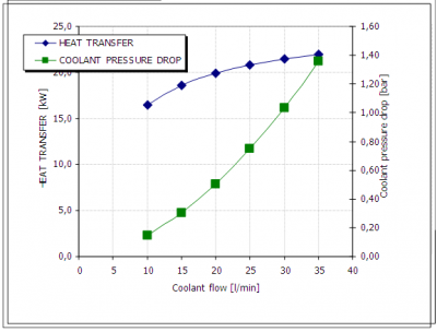
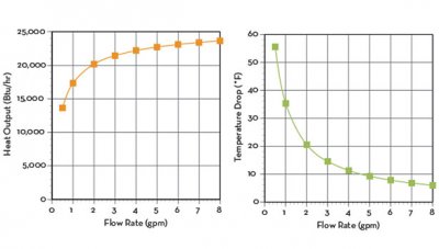
Below is a graph that shows the impact of coolant flow rate on IAC and total heat rejection. As you can tell, there is a region of strong 'gain' and then a region of 'diminished return'.

In conclusion, as squid correctly identifies, every system is different on the 'point of diminished return'. The related heat transfer physics provides an easy rule: the larger the heat exchanger or IC (and thus surface area) the greater the coolant flow rate required to hit flow saturation (or diminished returns). That is NOT to say that a larger heat exchanger will, by any means, perform worse than a small heat exchanger at identical flow rate, it is to say that the larger heat exchanger will reap more benefit from an 'increase' in flow rate.
Hope this helps!
BTW, I made the graphs above so please feel free to send me any questions related to their meaning.
Thanks,
Austin