Comprehensive IC Water Pump/System Test Data

Racer47

Doesn't have much to say
S197 Team Member
Joined
Sep 11, 2009
Posts
1,065
Reaction score
324
Location
SE Wis
Racer47, you are on the right track with your thinking. Just keep in mind the graphs you posted would be for relatively small liquid to air heat exchangers which is why they seem to assymptote at lower flow rates than what Squid is proclaiming. The necessity and benefit of flowrate is uniquely driven by the size of the heat exchangers in the loop.

Austin

Thanks for chiming in with some data. I know the flow numbers are not absolute. I was just looking for data. I know its a system thing like I said in post #64 of this thread

"So the added cost of going from the 50 to the 100 is probably not going to result in any meaningful IAT reduction for my KB and AFCO system. I bet the Mercedes systems are bigger and flow more water and see a real benefit from the CWA100's."
 

Department Of Boost

Alpha Geek
Joined
May 26, 2010
Posts
8,809
Reaction score
28
Thanks for chiming in with some data. I know the flow numbers are not absolute. I was just looking for data. I know its a system thing like I said in post #64 of this thread

"So the added cost of going from the 50 to the 100 is probably not going to result in any meaningful IAT reduction for my KB and AFCO system. I bet the Mercedes systems are bigger and flow more water and see a real benefit from the CWA100's."

I think you're looking at that backward. You have the most restrictive IC out there. You can use a high pressure pump more than anyone.
 

Nutter281

forum member
Joined
Mar 23, 2015
Posts
136
Reaction score
0
Location
Central Texas
I think you're looking at that backward. You have the most restrictive IC out there. You can use a high pressure pump more than anyone.

No.

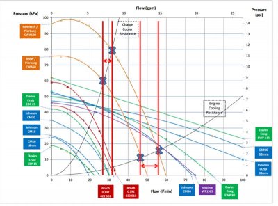
I don't know anything about the flow impedance characteristics of the KB IC or the Afco radiator. But, having a more restrictive intercooler probably means the overall size is smaller and thus, the point of flow saturation is lower. I'm not sure if the .pdf from Mercedes Benz shares any of the same hardware as Racer47, but please review the below picture.

Without making the assumption that everyone knows how to read a pump curve, the intersection point of the impedance curve (the two black upwards curves) and the pump curves reflects the actual operating point (shown with blue Xs). The impedance curve labeled "charge cooler resistance" is a very high flow impedance device compared to the "engine cooling resistance". (sidenote, be careful not confuse thermal resistance and flow resistance, these are both flow resistance curves). Looking at the graph below, which device 'has the most to gain' in operational flow rate when switching from CW50 to CW100 pump?

pump_Curves.jpg


It follows that smaller ICs are more restrictive and have less surface area and have larger "non-flowrate-impacted resistances" that do not improve with better flow. They will see less benefit from increases in coolant flow rate and the pumping power loss per GPM increase will cost significantly more in efficiency loss than a less restrictive larger heat exchanger.

That said, I have no idea what the impedance is of Racer47s setup or where it lies on the flow saturation curve with the current pump setup - just providing some guidance on how this should be considered.

Thanks,
Austin
 

Department Of Boost

Alpha Geek
Joined
May 26, 2010
Posts
8,809
Reaction score
28
No.

I don't know anything about the flow impedance characteristics of the KB IC or the Afco radiator. But, having a more restrictive intercooler probably means the overall size is smaller

It's not.

Care to change that hard "no" to a maybe?:whistle1:
 

Boone

Automotive Enthusiast
Joined
Feb 24, 2015
Posts
320
Reaction score
4
Location
High Point, NC
I love how we explain fluid dynamics with resistors and electrical resistance with water analogies. I'm guilty as well.

I do like the resistance model for this example though. Improve any aspect of the system, and overall results improve.

Higher air flow (greater pressure differential accross HE) = BETTER
Higher water flow (bigger pump and/or less restrictions) = better
More surface are for convection (bigger HE) = BETTER

I do appreciate the points you all have made. Takes me back 30 years to Thermo.

Now the questions (since I'm N/A and just an observer). Do these PD blowers make so much heat so fast that this will always be a problem? Is it reasonable to think it is even possible to cool them down in a 1/4 mile?
 

Department Of Boost

Alpha Geek
Joined
May 26, 2010
Posts
8,809
Reaction score
28
It follows that smaller ICs are more restrictive and have less surface area and have larger "non-flowrate-impacted resistances" that do not improve with better flow.
I'm not following how X surface area (large, med, small, whatever) doesn't improve with more flow rate. Assuming that there already isn't enough flow rate to remove the entire heat load. I get diminishing returns, I don't get "not improve" though.

They will see less benefit from increases in coolant flow rate and the pumping power loss per GPM increase will cost significantly more in efficiency loss than a less restrictive larger heat exchanger.
What cost? What are you "spending"?
 

Department Of Boost

Alpha Geek
Joined
May 26, 2010
Posts
8,809
Reaction score
28
Now the questions (since I'm N/A and just an observer). Do these PD blowers make so much heat so fast that this will always be a problem? Is it reasonable to think it is even possible to cool them down in a 1/4 mile?
Keeping them cool enough to run the 1/4 (an actual drag strip) is not that big of a deal......for most cars. When you start playing with 10lb+ of boost it gets more difficult. When you get to 15lb of boost it gets hard. At 20lb of boost it's almost impossible to do without ice water, e85 or both. That's at the strip where you get to cool the car down between passes though. If you're driving around on the street, sitting at stoplights, etc the system will heat saturate and most of the time if you were to punch it you won't make it 1/4mi before it starts to pull timing. That is with the "as delivered" systems that come with the PD kits.

When you add big heat exchangers and better pumps the situation improves. But unless you run "everything including the kitchen sink" you won't "solve" it.

The systems I have designed are way beyond what anyone else has done. Massive heat exchangers, up to 5x the flow rate and manifolds with composite heat barriers built in are still not bulletproof. And they're a metric fuck-ton better than everything else out there.

The A2W systems that you're getting with everyone's stuff but mine trace their lineage back 15+yrs when 6lb of boost was "big time", and they weren't even very good then. In this day an age where 10lb is entry level, 15lb is common and 20lb happens more than you would think that old technology is outclassed.

It's not that I'm a genius. I think I'm the only person making this stuff that has actually tried to solve the problem.
 

Pentalab

forum member
Joined
Mar 5, 2013
Posts
5,216
Reaction score
1,104
IF we had say...an unlimited supply of cool water, (swimming pool) then a pump, then into the IC..then discharged the heated water into a drain....... I would think that any increase in flow rate would be a huge benefit. On paper, a smallish IC should work..provided we stuff enough cool water..at an appropriate rate through it. Problem is... we have a closed loop. All that heat that is extracted from the IC...will ultimately have to be transferred to the air ( the air flowing through the HE).

The IC extracts the heat....the HE dumps it. IMO, any increase the flow rate in the loop is not going to buy you very much...unless the HE is a helluva lot bigger /and /or more air through the HE.

This whole thing depends on the application. 1/4 mile drag race...or 30 min road course session....... or tooling around downtown, with loads of red lights on a hot summer day.

Ice is cheap, so for 1/4 mile drag racing, would be a cheap and easy way to cool things down.

For tooling around town, perhaps a bigger HE..with a pair of fans night be more optimum. ( even though the fans typ run at 16 mph).

For road course work, the GT-500 HE, which is 3 1/8" thick, no HE fans, and a 13/14 GT-500 IC pump, ( or the 100 pump) would do the trick. (along with keeping the boost down to something reasonable, like perhaps 7-10 psi), plus un restricted upper + lower grilles, 100% distilled water + water wetter, and hood vents, ceramic coated LT's etc might work. 7-10 psi + 11:1 CR + 93 tune + LT's should provide enough tq /hp for most road course applications.

The HE won't work worth a damn if you can't get air flowing through it. This is no place for the oem upper grille as used on the 10-12 cars (replace it with the 7 bar grille). The HE is already being restricted by the bumper.

2 pumps in series has some merit, then you have redundancy.
 
Last edited:

Department Of Boost

Alpha Geek
Joined
May 26, 2010
Posts
8,809
Reaction score
28
The IC extracts the heat....the HE dumps it. IMO, any increase the flow rate in the loop is not going to buy you very much...unless the HE is a helluva lot bigger /and /or more air through the HE.
The hotter the water in the HE the more efficient it is.

The hotter the water is the faster you want to move it through the IC.

Faster = good.

"is not going to buy you very much"
This is a game of "not very much". That means you have to take as many "not very much's" as you can, whenever you can. It's the same as the weight savings saying, "Ounces add up to pounds".
 

Pentalab

forum member
Joined
Mar 5, 2013
Posts
5,216
Reaction score
1,104
The hotter the water in the HE the more efficient it is.

The hotter the water is the faster you want to move it through the IC.

Faster = good.

Ok, so install a smaller HE, to get the coolant even hotter inside it..... to increase it's ...'efficiency'. Nobody is about to do that.

The blower discharge produces X BTU's. You have to get rid of it....or at least enough of it, to get the IAT's down to something reasonable. So you require an IC / pump / HE to dump X amount of BTU's. This isn't rocket science.

It might help if 100% distilled water + water wetter was used..along with maximizing air flow through whatever HE is used. ( upper grille + hood vents + shrouding of the rads). Then use whatever pump you want, as long as it has enough pressure to do the job into whatever back pressure it encounters.

The mezziere pumps gag when presented with any amount of back pressure. My guess is they would be better suited for applications like a bilge pump in a boat..since 12 vdc is available...and no back pressure restrictions.

BTW, it looks like they make a 50/100/200/400 version of those pumps. The 13/14 GT-500 pump being the 50 model.

That 13/14 GT-500 HE + a 50/100 pump is probably going to be as good as it gets, unless you can come up with an even bigger HE..that will still fit.
 

Department Of Boost

Alpha Geek
Joined
May 26, 2010
Posts
8,809
Reaction score
28
Ok, so install a smaller HE, to get the coolant even hotter inside it..... to increase it's ...'efficiency'. Nobody is about to do that.
I NEVER said anything resembling that.

The blower discharge produces X BTU's. You have to get rid of it....or at least enough of it, to get the IAT's down to something reasonable. So you require an IC / pump / HE to dump X amount of BTU's. This isn't rocket science.
You mis-understood what I wrote and now you're being condescending? To the guy who has achieved the lowest IAT's of anyone......ever? Come on man. SMH.


That 13/14 GT-500 HE + a 50/100 pump is probably going to be as good as it gets, unless you can come up with an even bigger HE..that will still fit.
Already have.
 

Pentalab

forum member
Joined
Mar 5, 2013
Posts
5,216
Reaction score
1,104
Not being condescending. Re-run the IAT test you did previously, but on a 100 deg f day...on a 20 min track session. That may well result in some data that is useful..vs extrapolating from a 80 f day..and a short run with the blower on.

On a another note, when you ceramic coated the bottom of the IC, with no improvement, that still baffles me. But I see that these new high eff, gas fired hot water tanks all use ceramic coated 2-3" diam copper tubing inside the 40/60 gal tank. The copper tubing is wound into a coil, with the hot gases passing through the inside of the spiral wound coil. Old style low eff tanks used a single vertical tube to exhaust the combustion products...and the flue ran blazing hot.
New high eff versions are well < 140 F..where it exits the top of the tank. The high eff versions use 2" / 3" plastic PVC pipe to exhaust the combustion products to the outside ( via a small fan /blower).

Kitchen stoves with the 4 x hidden coils are all ceramic coated stove tops. Yet in both cases, the ceramic used, appears to conduct heat real good. The spiral wound copper tube inside the hot water tank is ceramic coated on both sides too.

Yet the ceramic coating on LT's reduces surface temp on the 8 x primarys by a whole bunch..as in several hundred degrees. So what gives ? Is it the type of ceramic used, or the coating process, or the thickness, or what ? On paper, your ceramic coated IC (which was also coated where it bolts to the heads) should have reduced the transfer of heat into the IC by a lot. I'm betting if the correct type of ceramic was used, your results would improve. That alone might reduce some of the heat soak issues.
 

Pentalab

forum member
Joined
Mar 5, 2013
Posts
5,216
Reaction score
1,104
What else that would work is water / meth. The oem wind shield washer bottle will last just long enough for a 20 min track session. The capacity could easily be increased of course. Carmen on the roush forum used a green /yellow /red led setup on the dash to indicate the water-meth level. You can also get multi colored leds, so only 1 required..instead of 3. A buddy here in town also uses water-meth. He tells me it typ last him 1 month for DD / hwy use.
 

Nutter281

forum member
Joined
Mar 23, 2015
Posts
136
Reaction score
0
Location
Central Texas
But, having a more restrictive intercooler probably means the overall size is smaller
It's not.

Care to change that hard "no" to a maybe?

You'll have to be more clear, then, on what you mean by "restrictive" as you noted racer47's to be the "most restrictive". Restrictive tends to imply the flow path has too few or too small of passages for fluid to pass through resulting in very high differential pressure across the device. I may have made a poor assumption you knew how to use the word 'restrictive' in the context of an IC? :whistle1:

I'm not following how X surface area (large, med, small, whatever) doesn't improve with more flow rate. Assuming that there already isn't enough flow rate to remove the entire heat load. I get diminishing returns, I don't get "not improve" though.

Did you even read my first post?

From Nutter281:
Does increased flow rate reduce the overall thermal resistance? Absolutely, if R3 and R4 go down, the sum of R1 + R2 + R3 + R4 + R5 + R6 will also go down. Is there a point where reducing R3 and R4 no longer appreciably decreases the thermal resistance? Absolutely.

What I 'also' said was that in the perfect analogy of two resistors in series, it literally doesn't matter if you increase flow rate to infinity, you can never take your total resistance lower than the sum of the other resistors in the series. A small heat exchanger will have very 'large' conductive and air-side resistances that won't change when the coolant flow rate is increased.


What cost? What are you "spending"?

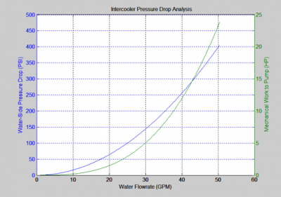
Pump power my dear boy. Doesn't matter if it is mechanical pulley or electrical via alternator going into your battery, energy to move the water is coming from 'somewhere'. See chart below - the pumping power is not negligible when you are chasing after that "not very much".

Pump_power.png

At some point, the horsepower you gain by decreased IATs will be less than the horsepower you spend to move the water faster - that is a fact. The heat exchanger in the attached graph was not 'particularly' restrictive - in fact, it is one that "you" might call the "least restrictive" :)

Also, keep in mind that the attached graph is for the IC only - flow rate is the same everywhere in the loop so increasing flow rate in the IC also means eating extra pump power through every other device, elbow, hose length, HE, etc.

I'm not sure if this is news or not, but Flowrate * Pressure Drop = Mechanical Work and Mechanical Work / Efficiency = Input Power (horse power). Unless you decouple your battery from the alternator and only power the pump from a large electrical capacitance, the pump power is coming out of your engine power.

Thanks,
Austin
 
Last edited:

Pentalab

forum member
Joined
Mar 5, 2013
Posts
5,216
Reaction score
1,104
You'll have to be more clear, then, on what you mean by "restrictive" as you noted racer47's to be the "most restrictive". Restrictive tends to imply the flow path has too few or too small of passages for fluid to pass through resulting in very high differential pressure across the device. I may have made a poor assumption you knew how to use the word 'restrictive' in the context of an IC? :whistle1:


Did you even read my first post?

From Nutter281:


What I 'also' said was that in the perfect analogy of two resistors in series, it literally doesn't matter if you increase flow rate to infinity, you can never take your total resistance lower than the sum of the other resistors in the series. A small heat exchanger will have very 'large' conductive and air-side resistances that won't change when the coolant flow rate is increased.


Pump power my dear boy. Doesn't matter if it is mechanical pulley or electrical via alternator going into your battery, energy to move the water is coming from 'somewhere'. See chart below - the pumping power is not negligible when you are chasing after that "not very much".

View attachment 55950

At some point, the horsepower you gain by decreased IATs will be less than the horsepower you spend to move the water faster - that is a fact. The heat exchanger in the attached graph was not 'particularly' restrictive - in fact, it is one that "you" might call the "least restrictive" :)

Also, keep in mind that the attached graph is for the IC only - flow rate is the same everywhere in the loop so increasing flow rate in the IC also means eating extra pump power through every other device, elbow, hose length, HE, etc.

I'm not sure if this is news or not, but Flowrate * Pressure Drop = Mechanical Work and Mechanical Work / Efficiency = Input Power (horse power). Unless you decouple your battery from the alternator and only power the pump from a large electrical capacitance, the pump power is coming out of your engine power.

Thanks,
Austin


Am I reading that graph correctly. 20 gpm requires 1.25 hp... and also 62.5 psi ?

40 gpm requires 12 hp + 256.25 psi ? To double the gpm, we now require 4.1 X the pressure...and also 10X the HP.

1 hp = 746 watts.... but that's only if the electric motor is 100% eff. Typ eff is 65% at the most. So 746 /.65 = 1148 watts.
1148 watts / 13 vdc = 88 Amps !

In the above 20 gpm case, with it's 1.25 hp requirement, then its 1435 watts = 110 amps !

If that's the case, now we are getting into the realm of plane nuts. A water pump driven off the fead belt might be a better option at that point, but won't flow high gpm...when at idle.

Will the IC -pump-HE- interconnecting hoses even handle 62.5 psi ? 256.25 psi would be a strain on fitting's, IC / HE Internals etc.

Per those graphs, 8-12 gpm is probably going to be as practical as it gets. After that, it's perhaps a bigger HE, + bigger diam interconnecting hoses + fittings etc..which should be done 1st..b4 any increase in pump size.

Even going from 10-20 gpm is no mean feat. What 20 gpm pump setup will actually flow 20 gpm @ 62.5 psi ?

Per the chart on post #84, several CWA-100's in series would be required to put a dent on anything.
 
Last edited:

palanza7

forum member
Joined
Apr 6, 2015
Posts
648
Reaction score
16
So why all this like epic intercooler and pump hair splitting when you can just run a ~800$ killer chiller setup and have 60 degree water all the time lol
 

Pentalab

forum member
Joined
Mar 5, 2013
Posts
5,216
Reaction score
1,104
So why all this like epic intercooler and pump hair splitting when you can just run a ~800$ killer chiller setup and have 60 degree water all the time lol

The Killer chiller is capable of lowering the coolant temps down to 40 F..which is way below the outside ambient air temp. But to pull that off, the HE has to be completely bypassed, or the coolant will be partially re-heated by the 80-100 F ambient air flowing through the HE.

I looked at some of the u tube KC vids. It took several minutes to get the coolant temps back down. The recovery time was a lot longer than I thought it would take..like in some cases 6-12 mins. All that heat is now being dumped into the AC rad.

The AC is in shut down mode when the car is WOT. ( I think that may be software related, and possibly could be defeated in software, but don't quote me on it) So you would have to wait and get the coolant down to a low temp, like 40-60F..1st, b4 you go WOT on the strip. It appears the recovery takes place between WOT pulls or runs on a road course. Dunno if it would even work on a road course..since they are always running sustained high rpm.

Does anybody know of success stories with folks using the KC..or any similar version, using freon and the AC rad /pump etc ?
 
Last edited:

palanza7

forum member
Joined
Apr 6, 2015
Posts
648
Reaction score
16
Good point about the air heating things up. You could probably just block off the front of the HE a bit to assist. Either way it has to be way better flowing say 65 degree water than just worrying about how much water you can pump and then cool down with 80 degree air. If you are at the strip im sure it's a lot cheaper to dump a bag of ice in a trunk tank though. But for everyday use I'm probably going to go with the kc before dropping 450 on a crazy pump. Hmm there is probably a point where you need the cold water to move faster through the intercooler though if you are really heating things up.
 

Wes06

forum member
Joined
Jan 21, 2012
Posts
5,383
Reaction score
59
Majority of tracks don't want a/c ran at the track. Condensation dripping off the car on the way down and some high HP car hits it
 

Support us!

Support Us - Become A Supporting Member Today!

Click Here For Details

Sponsor Links

Banner image
Back
Top