I’ve been getting some requests for information regarding how I did my wiring and whether there was a thread about it. Well, here’s the thread. It’s a long one, so proceed at your own risk!
First and foremost – Prepare! Second – take your time. If you’re in a hurry you will mess this up in a big way. Don’t even think about something like this without the wiring manual for your specific vehicle.
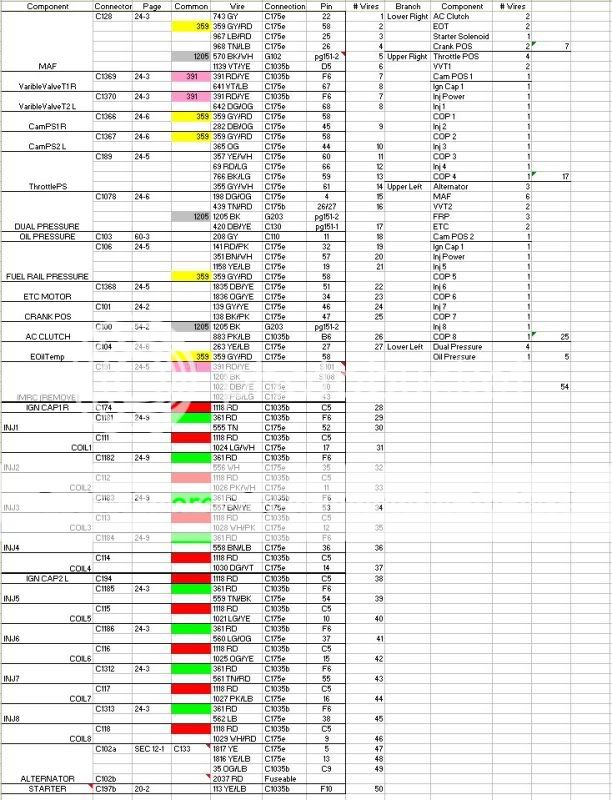
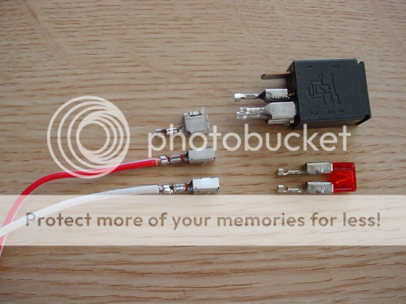
This is how I started, by going through the wiring manual and tracking every wire in the harness from end to end. I identified where splices were for common wires and planned which ones would need to be cut and rerouted. You need to know the pin location of every wire in every connector unless you just want to splice it downstream. I’m too anal to even think about that, but you can do it any way you think will live. The process I use for pinning the wire is illustrated below: You open to lower crimp on the connector and bend the wire back and forth until it creates a stress fracture at the crimp and breaks off clean. This is much cleaner than trying to cut it with snips. Insert the wire and crimp it at the lower crimp. THIS IS NOT A STRONG CRIMP, but it will hold the wire and give you a solid base for the soldered joint.
The next step is to label every connector and unwrap the harness. This is where you identify the wires that are separated into the transmission harness and run separately around the engine. These wires were long enough, after removing the common and IMRC wires, that I could rewrap and run them along the frame to the back of the engine.
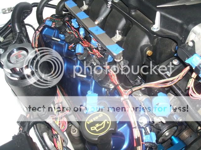
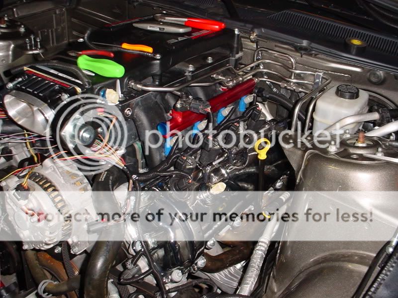
I started to rewire at the coils and injectors. Every coil and injector has a separate signal wire and each bank of each system runs a common power wire. The photo shows how I spaced the wiring at the same intervals as the coils / injectors and bundled them towards the front of the engine. For those of you with a shift light, this is the place to add that sensing wire. I did mine after the fact and ran off #4 coil, into the transmission portion of the harness.
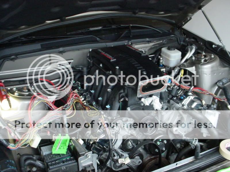
At this point I’ve reinstalled the blower with injectors and air tube to locate the fuel sensor, ETC and MAF. Those harnesses have been tied into everything else going across the front of the engine and tape wrapping is in place. I tape wrap everything the full length of the harness and then install convoluted tubing.
I’ve removed the air tube and finished this side of the harness. What you see is the complete harness for that side of the engine. I’ve also rerouted the harness that goes over the brake booster to under it. It is long enough to do that without cutting.
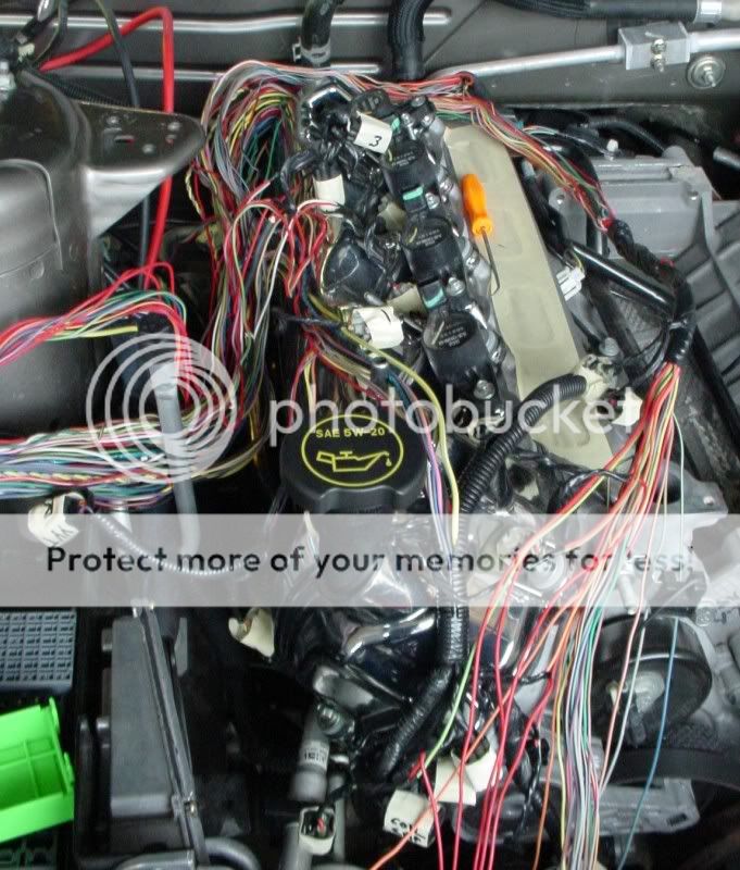
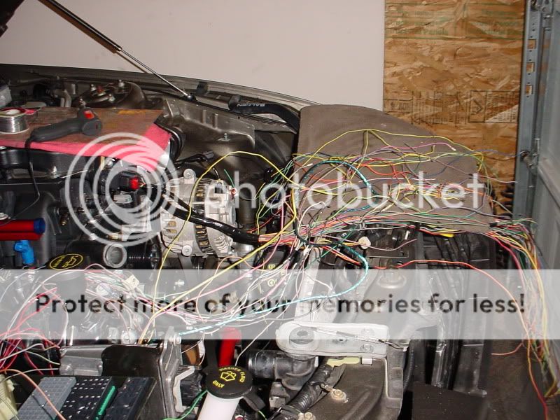
This mess where the tape ends is the driver side harness before it meets up with the passenger side. It includes everything around the throttle body and the alternator, with the exception of the main power lead. That I ran separately. The rest of the stuff draped over the valve cover is what’s coming out of the fuse box.
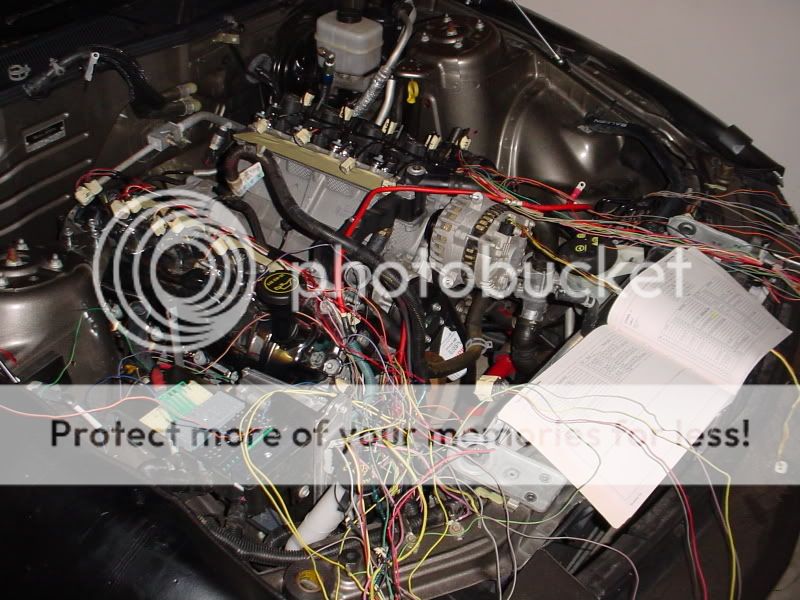
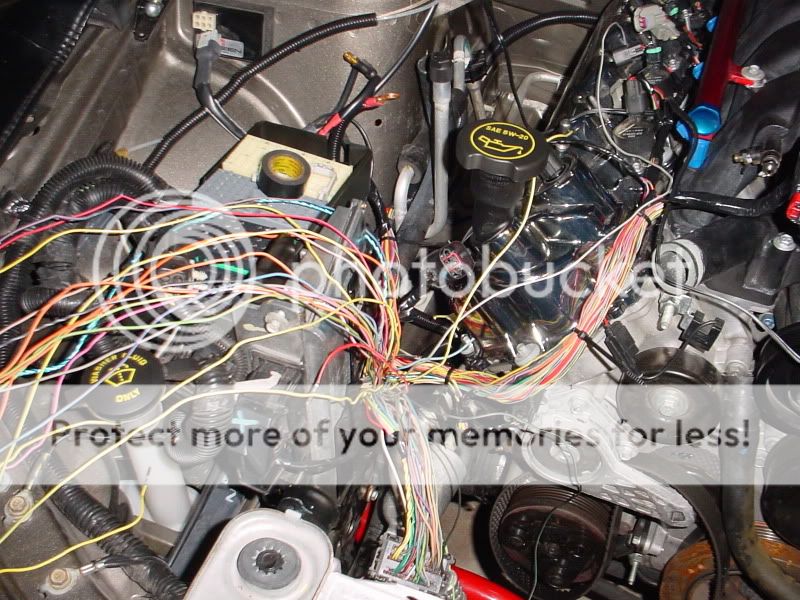
This is getting pretty close to complete, as the entire engine harness is now tied together and run to the frame rail. I’ve already split off everything going to the fuse box and have a lot of the harness back in the CPM plug at the bottom of the photo. The rest of these all go to the CPM.
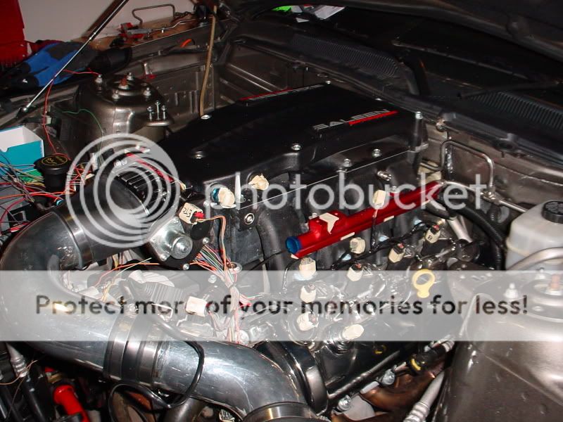
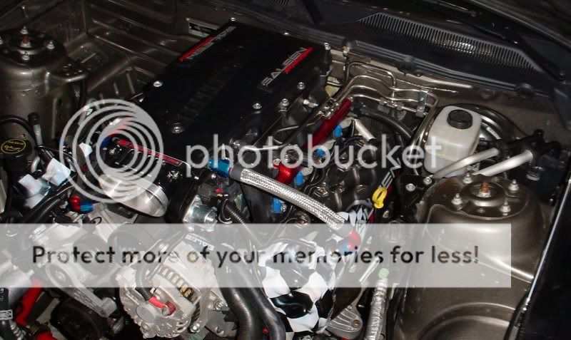
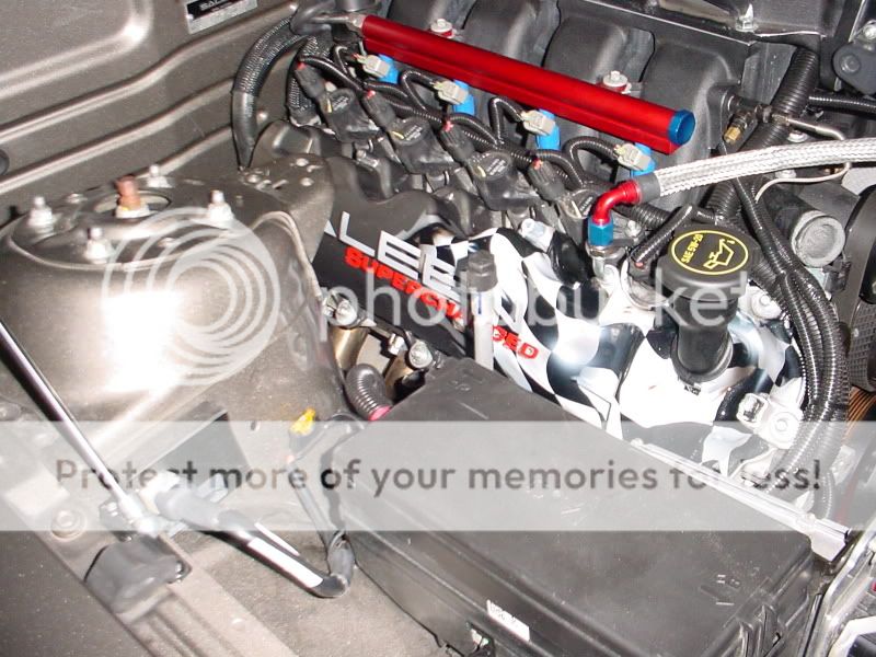
These are the completed shots from both sides of the engine. Of note is the routing around the front of the cylinder head.
This is a pretty quick brush around a job that took me nine 12-16 hour days to complete, including the tubing and battery relocation. This was also specific to my Saleen blower, so other applications will vary, but it should give anyone considering this kind of project some insight into what will be involved.
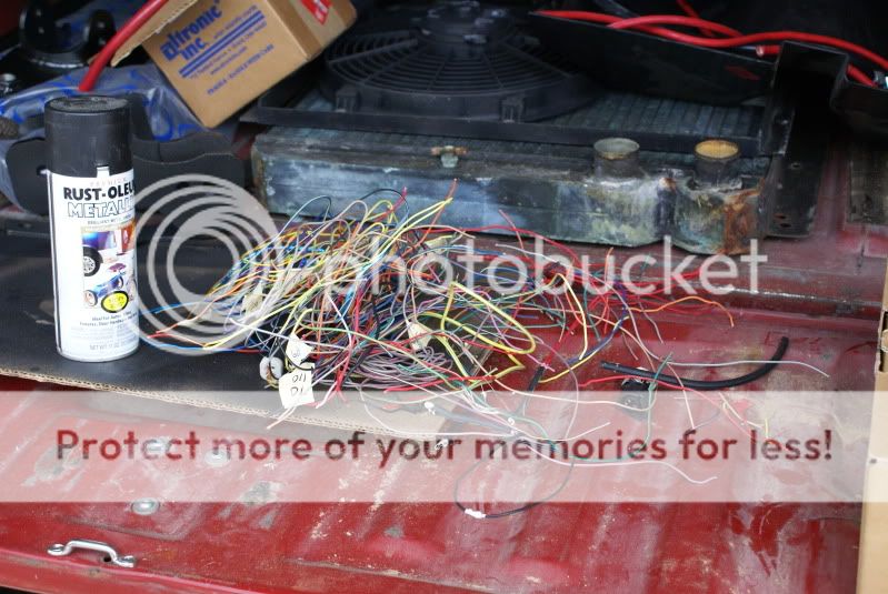
As a final note, this is the wiring that was left over after I completed the project.
First and foremost – Prepare! Second – take your time. If you’re in a hurry you will mess this up in a big way. Don’t even think about something like this without the wiring manual for your specific vehicle.
This is how I started, by going through the wiring manual and tracking every wire in the harness from end to end. I identified where splices were for common wires and planned which ones would need to be cut and rerouted. You need to know the pin location of every wire in every connector unless you just want to splice it downstream. I’m too anal to even think about that, but you can do it any way you think will live. The process I use for pinning the wire is illustrated below: You open to lower crimp on the connector and bend the wire back and forth until it creates a stress fracture at the crimp and breaks off clean. This is much cleaner than trying to cut it with snips. Insert the wire and crimp it at the lower crimp. THIS IS NOT A STRONG CRIMP, but it will hold the wire and give you a solid base for the soldered joint.
The next step is to label every connector and unwrap the harness. This is where you identify the wires that are separated into the transmission harness and run separately around the engine. These wires were long enough, after removing the common and IMRC wires, that I could rewrap and run them along the frame to the back of the engine.
I started to rewire at the coils and injectors. Every coil and injector has a separate signal wire and each bank of each system runs a common power wire. The photo shows how I spaced the wiring at the same intervals as the coils / injectors and bundled them towards the front of the engine. For those of you with a shift light, this is the place to add that sensing wire. I did mine after the fact and ran off #4 coil, into the transmission portion of the harness.
At this point I’ve reinstalled the blower with injectors and air tube to locate the fuel sensor, ETC and MAF. Those harnesses have been tied into everything else going across the front of the engine and tape wrapping is in place. I tape wrap everything the full length of the harness and then install convoluted tubing.
I’ve removed the air tube and finished this side of the harness. What you see is the complete harness for that side of the engine. I’ve also rerouted the harness that goes over the brake booster to under it. It is long enough to do that without cutting.
This mess where the tape ends is the driver side harness before it meets up with the passenger side. It includes everything around the throttle body and the alternator, with the exception of the main power lead. That I ran separately. The rest of the stuff draped over the valve cover is what’s coming out of the fuse box.
This is getting pretty close to complete, as the entire engine harness is now tied together and run to the frame rail. I’ve already split off everything going to the fuse box and have a lot of the harness back in the CPM plug at the bottom of the photo. The rest of these all go to the CPM.
These are the completed shots from both sides of the engine. Of note is the routing around the front of the cylinder head.
This is a pretty quick brush around a job that took me nine 12-16 hour days to complete, including the tubing and battery relocation. This was also specific to my Saleen blower, so other applications will vary, but it should give anyone considering this kind of project some insight into what will be involved.
As a final note, this is the wiring that was left over after I completed the project.
 about time, this will be mine some day.....