Ignition switch fuse

Marc Aguilar

Junior Member
Joined
Feb 20, 2022
Posts
9
Reaction score
0
Location
El paso
I have single turbo on my 2011 mustang gt and when I turn the car on and starts to warm up a bit the ignition switch feed fuse keeps popping any ideas why it happens i dont have the tune for the turbo i just installed it so dont know if its that it draws too much power or what
 

JEWC_Motorsports

S197 Junkie
S197 Team Member
Joined
Aug 22, 2010
Posts
20,476
Reaction score
1,598
Location
Texas
I have single turbo on my 2011 mustang gt and when I turn the car on and starts to warm up a bit the ignition switch feed fuse keeps popping any ideas why it happens i dont have the tune for the turbo i just installed it so dont know if its that it draws too much power or what
Did this start after the turbo install? If so there is a wire grounding out.
 

Marc Aguilar

Junior Member
Joined
Feb 20, 2022
Posts
9
Reaction score
0
Location
El paso
started when i let the car warm up and i just barely slowing reved it to 2.5k and it popped it but im assuming that the fuse that i plugged in the scavenger pump passes though they ignition fuse and well its overloading the fuse causing it to pop
 

DieHarder

Senior Member
Joined
Nov 9, 2019
Posts
1,468
Reaction score
758
Great that you're aware of where/what the issue is.... Since it's popping the fuse you know the circuit is not sized properly to handle the increase in current. Would be better to put the load side on it's own circuit with a relay that separates out the higher current line (for the pump) by itself w/larger lines to handle the increased current according to the amp needs of the scavenger pump (should be on the pump or paperwork that came with it). Similar to how the radiator fans operate (i.e. low current side/ground activates relay w/key on; high current/power side of the relay (w/appropriately sized fuse) provides power directly to scavenger pump).

For reference here's a diagram from the wiring diagrams manual:
https://iihs.net/fsm/?d=40&f=Power Distribution-SJB.pdf&p=11
 
Last edited:

Marc Aguilar

Junior Member
Joined
Feb 20, 2022
Posts
9
Reaction score
0
Location
El paso
I know thanks im pretty sure that thats what i need to do is run a separate line for the pump itself and have it operate alone cause it just keeps popping it and dont want it to fet worse
 

DieHarder

Senior Member
Joined
Nov 9, 2019
Posts
1,468
Reaction score
758
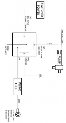
Where is the scavenger pump exactly? Did you find out what the amp requirements are for it? Whenever wiring pumps, it's important to add a relay to the system. Failure to do so will cause excessive heat in the wiring and create a risk of failure/fire. The problem is the amount of power being drawn by the high output pump. A relay works by using a switch (or switched power) to run low amperage 12 volts to the relay as a “signal”. The relay then acts as an electrical switch that activates an internal switch that draws power straight from a high current fused battery connection and sends it to the pump. The low current switched power/trigger never gets routed to the pump. Generally you'll have a larger gauge wire going to the pump because the pump pulls much greater current/power.

The easiest way to do this is to install a standalone relay somewhere in the engine bay (you need to know how many amps to determine size but most (30-40 amp) will handle current needs of most pumps just fine). Activate the relay with any 12v source that becomes active with key-on. If in the engine bay one of the RF noise suppressors on the timing cover are easy to tap into. The other side (power) is connected to a 12v source like the battery or the hot post on your underhood fuse box & gnd.

They're readily available and inexpensive.... https://www.amazon.com/dp/B017VDI0GY/ref=sm_n_ma_dka_US_pr_ran_0_1?adId=B017VDI0GY&creativeASIN=B017VDI0GY&linkId=22392e3fb4238d5fee5e4f1118c89515&tag=the12volt-20&linkCode=w43&ref-refURL=https://www.the12volt.com/relays/spdt-and-spst-automotive-relays.asp&slotNum=0&imprToken=e68bc5972c036f1a7257d6398c626b3d&adType=smart&adMode=manual&adFormat=grid&impressionTimestamp=1645538558787

For a typical SPDT circuit see diagram below (borrowed from an install for a water pump).

SPDT_Switch_Wiring.png
 

Support us!

Support Us - Become A Supporting Member Today!

Click Here For Details

Sponsor Links

Banner image
Back
Top