Sky Render's Build Thread

Pentalab

forum member
Joined
Mar 5, 2013
Posts
5,217
Reaction score
1,104
My FRPP FRS-500 mufflers sound good on my 2010. Right after the JBA LT's and JBA high flow catted H went in years later....then the drone started. (It was also way too loud).

The "too loud" problem is not the LT's... it's caused by the high flow cats. The drone was around 1900 rpm.

The fix was to install a pair of Pypes M80's. These were installed after the H..and just b4 the rear axle. Problem solved. No more drone... and not as loud.

I wasn't about to replace the megabuck FRPP mufflers..( now $600.00 per pair). The pypes M80's are cheap at AM.. $44.00 each..and made from 304 SS.
 

Sky Render

Stig's Retarded Cousin
S197 Team Member
Joined
Feb 24, 2011
Posts
9,463
Reaction score
357
Location
NW of Baltimore, MD
The drone has more to do with a lack of chambered muffler and/or resonators than with the cats, though having no cats would definitely exacerbate any resonance issues.
 

Pentalab

forum member
Joined
Mar 5, 2013
Posts
5,217
Reaction score
1,104
The drone has more to do with a lack of chambered muffler and/or resonators than with the cats, though having no cats would definitely exacerbate any resonance issues.

FRPP guarantees..."no drone" on their FRS-500 muffler's..and they are correct...... but only when using oem cats + exhaust manifold ! The 05-10 cars never came with resonator's (the 11-14 cars come with 3.5" resonator's).

The LT's were well worth the install effort. The increase in TQ from idle to redline was easily noticeable. b4 (for test purposes), it would semi gag when the lights turn green...and starting off in 3rd gear from 600 rpm. After the LT's went in.. it just goes. Tried it again, but with gas mashed... ( and now the blower on)...and also in 3rd gear.... then it lays a bit of rubber..and off we go....to almost 100 mph..all in 3rd gear.

The aluminum DS is another "freebie"..another 30 ft lbs of tq @ 2.5 krpm.

BTW, I read all 5 parts of your build on motoiq. It was very informative...and well written.
 

Sky Render

Stig's Retarded Cousin
S197 Team Member
Joined
Feb 24, 2011
Posts
9,463
Reaction score
357
Location
NW of Baltimore, MD
FRPP guarantees..."no drone" on their FRS-500 muffler's..and they are correct...... but only when using oem cats + exhaust manifold ! The 05-10 cars never came with resonator's (the 11-14 cars come with 3.5" resonator's).

Well, I've still got the stock headers, downpipes, and cats, so... I've also heard using the Corsa system with no cats ("offroad pipes") sounds bloody awful. So you might have a point there.

The LT's were well worth the install effort. The increase in TQ from idle to redline was easily noticeable. b4 (for test purposes), it would semi gag when the lights turn green...and starting off in 3rd gear from 600 rpm. After the LT's went in.. it just goes. Tried it again, but with gas mashed... ( and now the blower on)...and also in 3rd gear.... then it lays a bit of rubber..and off we go....to almost 100 mph..all in 3rd gear.

I live in Maryland. I have not seen conclusive proof that I can get this car to pass emissions with long-tube headers, even with high-flow cats. Until then, my exhaust system pre-crossover-pipe is staying stock.

BTW, I read all 5 parts of your build on motoiq. It was very informative...and well written.

Thank you! :hi:
 

Sky Render

Stig's Retarded Cousin
S197 Team Member
Joined
Feb 24, 2011
Posts
9,463
Reaction score
357
Location
NW of Baltimore, MD
30ft lbs from an aluminum DS? Any supporting evidence?

So installing a lighter flywheel, driveshaft, or any rotational drivetrain part doesn't actually add horsepower. I think everyone knows that. But on a dyno, it does show up as increased power/torque because there are now less drivetrain losses, if that makes any sense.

30 torques sounds like a LOT, though.
 

skwerl

tree hugger
Joined
Aug 6, 2011
Posts
16,199
Reaction score
1,147
Location
central Florida
I think the 30 ft-lb claim is 'rounded up' from about 21. The rich kids over on fnsweet might believe those numbers but around here that's not gonna fly.
 

NoTicket

forum member
Joined
Jun 2, 2013
Posts
303
Reaction score
0
Pentalab, you are the best source of information on this forum. You should start a build thread.
 

Pentalab

forum member
Joined
Mar 5, 2013
Posts
5,217
Reaction score
1,104
So installing a lighter flywheel, driveshaft, or any rotational drivetrain part doesn't actually add horsepower. I think everyone knows that. But on a dyno, it does show up as increased power/torque because there are now less drivetrain losses, if that makes any sense.

30 torques sounds like a LOT, though.

There are several b4 + after dyno sheets depicting this.....http://www.stage3motorsports.com/CD...-Performance-1-Piece-Aluminum-Driveshaft.html
Most DS maker's will typ tout a .22 sec redux in 1/4 mile ET. After some research, it's typ .16-.18 sec. Are the many dyno b4 + after dyno sheets credible...who knows ? I only wish I had done a b4 and after dyno..after each individual mod. I only did 1 dyno run b4 the mods....and 5 dyno runs, ( run back to back) after all mods completed...so I have no clue how much was gained from each individual mod.

If all the various 1 piece AL-DS manufacturer's are falsifying dyno results... it's not a good scene.

With oem Roush tune... I had 346 rwhp / 324 rwtq.. (and 260 rwtq @ 2200 rpm). After ALL mods.. (which included frpp twin 62mm TB, LT's /hi flow catted H), DSS-DS and a 94 octane tune)... it all increased to... 387 rwhp / 370 rwtq (and 340 rwtq @ 2200 rpm). The 80 ft lb increase @ 2200 rpm came from somewhere. How much from the LT's /hi flow catted H/ bigger TB / DSS-DS /94 tune..I have no clue. I highly suspect that a chunk of it came from the DS..since most DS dyno sheets show a peak in tq right around +/- 2500 rpm for a 1 piece AL shaft.

My max tq increased by 46ft lbs @ 4250 rpm.... but a whopping 80 ft lbs @ 2250 rpm. The "after dyno" depicts the combined results of all the mods. (I kept the oem blower pulley too, same boost b4 and after.. 5.8 psi).

On a similar note...at our local .4 mile oval stock car track.... the visiting cars were all using identical engs to the local folks..the only exception being the flywheel. Those with oem heavy flywheels (both local and from out of town) all ran dead last..go figure. They announced that the oem heavier flywheels were a detriment. 4 weeks later......and it was a far different end result. Folks with the oem heavy flywheels had all replaced em with lighter ones, ( they have a min weight for flywheels)..and were doing extremely well in the final results.

The DSS-DS 1 piece shaft is a lot lighter than the oem 2 piece steel clunker + it's cxr bearing and extra u joint, etc. The weight savings got partly negated by my steeda rear STB + steeda triangular sub frame connector's and the BMR tunnel brace + DS safety loop.
 
Last edited:

kcbrown

forum member
Joined
Jul 24, 2013
Posts
655
Reaction score
5
So installing a lighter flywheel, driveshaft, or any rotational drivetrain part doesn't actually add horsepower. I think everyone knows that. But on a dyno, it does show up as increased power/torque because there are now less drivetrain losses, if that makes any sense.

30 torques sounds like a LOT, though.

Seems like it should be possible to compute how much of an improvement you'd see, actually.

Driveshafts are generally hollow, so the bulk of their weight is at the periphery. The stock driveshaft weighs 38 pounds. The aluminum driveshaft is about 20 pounds lighter.

But the problem is that the weight isn't the entire part of the story. Take a look at this image, that shows both the stock driveshaft and a 3.5" aluminum driveshaft side by side:


What determines how much rotational resistance is presented by a rotating body is its moment of inertia, otherwise known as its angular mass. The moment of inertia is computed by breaking up the mass into lots of tiny bits, multiplying the mass of each bit by the square of the distance of that bit from the center of rotation, and adding all of those results together.

If we assume the mass of the driveshaft is evenly distributed along its length and about its center axis, then its moment of inertia would be (m*r^2)/2 (see http://en.wikipedia.org/wiki/List_of_moments_of_inertia, which has formulae for the moments of inertia for various shapes. I'm using the cylindrical shell with open ends as the approximate shape for this exercise).

Now, the stock driveshaft appears to have a diameter about 3/4 that of the aluminum driveshaft (based on measuring the diameters in Photoshop) for half its length, and 5/6 for the other half. Considering the radii are being squared in the formula, that puts the average diameter for the stock driveshaft at about 0.8 that of the aluminum one. The aluminum driveshaft in the above is 3.5", so that would make the stock driveshaft about 2.75" in diameter on average, for the purpose of a moment of inertia calculation.

But what we really want to know here is the ratio of the moments of inertia of the two driveshafts. The ratio of the masses is about 18/38, or about 0.47. The ratio of the square of the radii is 1.62. Multiply those together, and the aluminum driveshaft has a moment of inertia about 0.77 that of the stock driveshaft.

Hence, the accelerative losses for the aluminum driveshaft are about 0.77 those of the stock driveshaft.

But how much is that, really?

To know that, we have to know how much of a rotational rate gain in a given period of time the driveshaft will go through when accelerating the car. But that depends on the actual acceleration of the car, combined with the rear end ratio. The smaller that acceleration, the less of a difference the driveshaft is going to make. Similarly, the lower the rear end ratio, the less of a difference the driveshaft will make. So the greatest gain will be had at the lowest speeds, where the acceleration is greatest, and the largest rear end ratios. We can use the 0-60 time as a decent benchmark here.

Let's assume a 0-60 time of 4 seconds, and a rear end ratio of 3.73:1. With 27" diameter tires (which is what you have with stock Track Pack wheels and tires), going from 0-60 mph (i.e., 0 to 1056 in/sec) represents a change of 12.45 rotations per second at the rear wheels, or 46.4 revolutions per second of the driveshaft. Over 4 seconds, that means a change of 11.6 revolutions per second of the driveshaft each second.

How much torque would it take to rotate the aluminum driveshaft from 0 to 11.6 RPS in one second? The driveshaft is 18 pounds, the diameter 3.5". Its moment of inertia is thus 27.6 lb-in^2. It would thus take a torque of 27.6 in-lb to accelerate the driveshaft by one radian/sec in one second. 11.6 RPS is 36.4 radians/sec, so you need a torque of about 1005 in-lb to accelerate the driveshaft at that rate, or about 84 ft-lb.

The amount of torque required to accelerate the stock driveshaft at the same rate is about 1.3 times that, or 109 ft-lb.

Hence, the torque improvement for a 0-60 run in the above example is going to be about 25 ft-lbs.

For a car that's even faster (like a supercharged car), the torque requirements to accelerate the driveshaft will be greater, and so will the torque difference by going with an aluminum driveshaft. Based on the above calculation, a 30 ft-lb improvement seems reasonable.

What's most interesting about the above, though, is that going with a taller rear-end reduces the torque demands of the driveshaft, simply because the amount of rotational change required of the driveshaft to accelerate the car is reduced. Going from 3.73 to 3.31 would get you maybe 12 ft-lbs for a 4-second 0-60 run in a car with the stock driveshaft. Of course, that also reduces the torque multiplication factor between the engine and the wheels, and so you don't necessarily gain any acceleration as a result. There ain't no such thing as a free lunch here, either.


Another interesting conclusion is that dynos will give you the most accurate results as regards the torque of the engine if they minimize the rate at which the drivetrain accelerates. The amount of improvement you see in the dyno numbers when going from a stock driveshaft to a lightweight driveshaft will depend enormously on how quickly the drivetrain accelerates during the dyno run. If you know the amount of time it takes to do the run and the speed range of the rear wheels during the run, you can compute a rough estimate of the parasitic driveshaft torque drag.
 
Last edited:

Pentalab

forum member
Joined
Mar 5, 2013
Posts
5,217
Reaction score
1,104
Sorry, I just saw this. That's an interesting piece. I'd definitely consider playing with it. It would allow the use of the Aeroforce gauge(s) and a data logger!

I had aeroforce send me the same heavy duty Y cable...along with 3 x gauges.

Gauges 1+2 are both cabled into the same OBD ( right angle) plug. Gauge 3 has it's own cable + (right angle) plug. Each right angle plug then goes into the Y.


2-3 gauges will provide up to 4-6 aux inputs..for stuff like oil pressure, oil temp etc, AFR bung for each bank, etc.

The only drawback to the Y splitter is it ends up a bit of a dogs breakfast. The 2 x portions of the Y have to be carefully folded back and ty rapped.

Toss in the aux stuff..and it becomes a lot of cabling.

1/2 of the Y can be used for data logging. Each gauge draws aprx 50 ma.
Each leg of the Y is aprx 12-14" long. It's a heavy duty Y cable..well made.
 

Sky Render

Stig's Retarded Cousin
S197 Team Member
Joined
Feb 24, 2011
Posts
9,463
Reaction score
357
Location
NW of Baltimore, MD
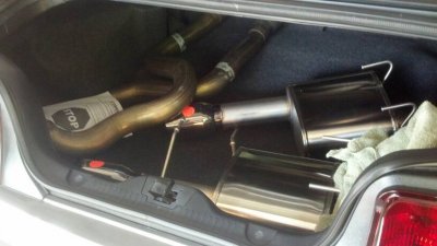
Trunk full of exhaust!

uploadfromtaptalk1400841771854.jpg

Those are the stock over-axle pipes and the Corsa Xtreme mufflers. I had to take the mufflers out of the box to fit them. The X-pipe (not shown) is on the back seat in it's box.

Fitting a full cat-back exhaust system into an S197 is like a jigsaw puzzle.

Sent from my toilet using Tapatalk
 

NoTicket

forum member
Joined
Jun 2, 2013
Posts
303
Reaction score
0
kcbrown,

Your calculations are reasonably spot on but you are neglecting one of the more important aspects of why claims of 30tq increases are ridiculous.

Only a small amount of the torque that is applied to rotate the driveshaft is lost through vibration, heat, etc. The rest of it is transmitted immediately or stored and released later.

The car puts out 390 lb-ft at the crank and about 355 lb-ft at the wheels STOCK. Even if the loss was reduced by the ratios you listed you are more realistically seeing a gain in the range of 25/109 * 35. (Torque reductions / original torque required * original rwtq lost). That is only 8 lb-ft and that is assuming that all drivetrain loss was through the driveshaft. It isn't. There is significant loss of torque and power through the differential/diff fluid, transmission/fluid.

I don't think I need to also point out that a 25rwtq increase from a driveshaft would actually put you at near 100% crank torque.
 
Last edited:

Sky Render

Stig's Retarded Cousin
S197 Team Member
Joined
Feb 24, 2011
Posts
9,463
Reaction score
357
Location
NW of Baltimore, MD
Well thank you!

Shep and I are agreeing on too many things lately; we need to start another argument.
 

kcbrown

forum member
Joined
Jul 24, 2013
Posts
655
Reaction score
5
kcbrown,

Your calculations are reasonably spot on but you are neglecting one of the more important aspects of why claims of 30tq increases are ridiculous.

Only a small amount of the torque that is applied to rotate the driveshaft is lost through vibration, heat, etc. The rest of it is transmitted immediately or stored and released later.

Well, no. Just like the car has mass and requires torque at the wheels to accelerate, so too does the driveshaft.

This is a matter of physics. The torque required to accelerate the rotation of the driveshaft is purely a function of its moment of inertia and the desired acceleration rate, just like the force required to accelerate the car is a function of the car's mass and the desired acceleration rate.

The torque used to accelerate the driveshaft is unavailable for use elsewhere. That's why I called it "parasitic". But it's not quite like friction, which requires a constant force just to maintain a velocity. Torque here is required only for acceleration.

The car puts out 390 lb-ft at the crank and about 355 lb-ft at the wheels STOCK. Even if the loss was reduced by the ratios you listed you are more realistically seeing a gain in the range of 25/109 * 35. (Torque reductions / original torque required * original rwtq lost). That is only 8 lb-ft and that is assuming that all drivetrain loss was through the driveshaft. It isn't. There is significant loss of torque and power through the differential/diff fluid, transmission/fluid.
There are a couple of additional factors that come into play here.

Firstly, the torque required to spin the driveshaft is being supplied through the transmission. A 0-60 run occurs in first and second gears, typically. On the MT-82, those gears have ratios of 3.66 and 2.43. The available torque of the engine is multiplied by those ratios. So the torque change due to changing the driveshaft as seen at the crankshaft is somewhere between 6.8 and 10.3 ft-lbs. Out of nearly 400 ft-lb of available torque, that's not a whole lot.

Secondly, I wasn't describing the torque difference at the rear wheels, only the torque required to accelerate the driveshaft. Put simply, I forgot that the 30 ft-lb number was claimed to be at the rear wheels.

If you want to know the torque difference at the rear wheels, you have to account for the differential ratio when describing how that difference would be seen at the rear wheels. In this case, the torque difference would be divided by the rear end ratio, so that 25 ft-lb difference would show up at the rear wheels as a 6.7 ft-lb gain, and then only if the acceleration rate is equivalent to a 4-second 0-60 pass.


ETA: Ooops. I was confused, and there's no strikethrough option for text, so I have "whited out" the incorrect bit in the above. The rear end ratio is the ratio of the revolutions of the driveshaft versus revolutions of the wheels. As such, torque at the driveshaft is multiplied by the ratio to get torque at the rear wheels. 25 ft-lb of difference at the driveshaft would show up as 93 ft-lb at the wheels. However, the dyno is clearly accounting for that ratio already, else the engine torque would be multiplied by it in the output. Hence, you really would see about 25 ft-lb of difference at the rear wheels on the dyno, assuming the drivetrain acceleration is the same as what it is during a 4 second 0-60 pass.


I don't think I need to also point out that a 25rwtq increase from a driveshaft would actually put you at near 100% crank torque.
Actually, it wouldn't. Not even close, at least during a 0-60 run. Assuming the 25 rwtq you're talking about already accounts for the rear end ratio, such an increase would be seen through the gears as either a 6.8 ft-lb or 10.3 ft-lb increase at the crank.


How much of a rear wheel torque increase you'd see on the dyno depends entirely on how fast the drivetrain is accelerating during the dyno run. If you tell me the amount of time it takes to go from a start of, say, 2000 RPM, to the redline of 6850, I can compute the acceleration of the driveshaft and tell you how much of a rear wheel torque difference you'd see on the dyno by changing it out.
 
Last edited:

Support us!

Support Us - Become A Supporting Member Today!

Click Here For Details

Sponsor Links

Banner image
Back
Top