2005 GT MAF 5V Problem

Laga

Senior Member
Joined
Aug 10, 2019
Posts
1,138
Reaction score
657
Location
Chicago
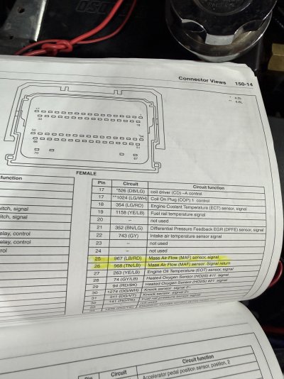
Car was running like shit after trans repair. Had to sit for two months due to family and health problems. Then, Found out both header gaskets were leaking. I could remove top nuts, but can’t work underneath car anymore. Take it to mechanic, he finishes gasket job. In doing so, he swaps upstream O2 sensors. I can fix this with help from kids. Car still runs like shit. Sent datalog to Lito and he says MAF not working. I test everything and find no 5V source going to MAF. All grounds are good. Almost all sensors use a 5V signal from ECM. I test TBPS, and fuel pressure sensor, and they have full 5V. I locate MAF source on pin 25 of bottom ECM connector. I gently clean everything. I have continuity from ECM connector to MAF connector, but no 5V.
It appears that ECM needs repair as pin 25 is dead. Am I missing anything ?
IMG_0560.jpeg
 

JC SSP

Senior Member
Joined
Nov 8, 2022
Posts
2,380
Reaction score
1,435
Location
FL
What codes do you have?

Could something have been damaged (pinched) when tranny was worked on?
 

Laga

Senior Member
Joined
Aug 10, 2019
Posts
1,138
Reaction score
657
Location
Chicago
only codes were for the O2 sensors being switched. No wires have been pinched.
 

JC SSP

Senior Member
Joined
Nov 8, 2022
Posts
2,380
Reaction score
1,435
Location
FL
Ok I had several codes pop up few weeks ago including upper & lower R/L O2 and TPS… turned out to be the TB assembly.
 

GlassTop09

Senior Member
Joined
May 24, 2019
Posts
1,407
Reaction score
881
Location
Farmington, NM
Car was running like shit after trans repair. Had to sit for two months due to family and health problems. Then, Found out both header gaskets were leaking. I could remove top nuts, but can’t work underneath car anymore. Take it to mechanic, he finishes gasket job. In doing so, he swaps upstream O2 sensors. I can fix this with help from kids. Car still runs like shit. Sent datalog to Lito and he says MAF not working. I test everything and find no 5V source going to MAF. All grounds are good. Almost all sensors use a 5V signal from ECM. I test TBPS, and fuel pressure sensor, and they have full 5V. I locate MAF source on pin 25 of bottom ECM connector. I gently clean everything. I have continuity from ECM connector to MAF connector, but no 5V.
It appears that ECM needs repair as pin 25 is dead. Am I missing anything ?
View attachment 117562
Laga,
From what you've posted & seeing the wiring labeling, you're pretty much on the right track..................only thing I can't determine is that you've checked pin 25 for the actual 5v+ power off the pin @ ECU board (pin 26 is the signal return.......this is the adjustment to the 5v+ power to the MAF coming back from the MAF after the 12v+ hot wire voltage scaling correction off passing airflow thru MAF slot........this is how the ECU actually measures airmass density thru the change in the 5v+ signal pre MAF vs post MAF........you typed "it appears"......).

Since this 5v+ comes directly off the ECU's onboard transformer (transforms 12v+ to 5v+ to feed all sensors that use this 5v+ power..........) & that 25 pin is tested\verified to be dead, then this pin trace on the ECU board between the transformer & this pin 25 has failed, but the onboard transformer itself hasn't (you've noted that this 5v+ reference is present at all other sensors except the MAF......) thus all other board traces are intact..........soooo, technically, you could tap into 1 of the live 5v+ wires to supply this reference to the MAF off pin 25's wire.......if this doesn't cause other issues w\ voltage offset throwing off the signal return voltage between the 2 sensors being fed from a common power source.......a reason IMHO why the MAF has its own separate 5v+ reference trace off the ECU board.

Otherwise, you're looking at an ECU board repair\replacement if pin 25 is truly dead...........but you also didn't mention that the 12v+ hot wire reference (the part you worked on earlier.......) is working either thus I'll assume that this side is good, yes?

Well, hope this helps you.........not a good situation in either case for a simple solution but it's the best I can provide.
 

Laga

Senior Member
Joined
Aug 10, 2019
Posts
1,138
Reaction score
657
Location
Chicago
Laga,
From what you've posted & seeing the wiring labeling, you're pretty much on the right track..................only thing I can't determine is that you've checked pin 25 for the actual 5v+ power off the pin @ ECU board (pin 26 is the signal return.......this is the adjustment to the 5v+ power to the MAF coming back from the MAF after the 12v+ hot wire voltage scaling correction off passing airflow thru MAF slot........this is how the ECU actually measures airmass density thru the change in the 5v+ signal pre MAF vs post MAF........you typed "it appears"......).

Since this 5v+ comes directly off the ECU's onboard transformer (transforms 12v+ to 5v+ to feed all sensors that use this 5v+ power..........) & that 25 pin is tested\verified to be dead, then this pin trace on the ECU board between the transformer & this pin 25 has failed, but the onboard transformer itself hasn't (you've noted that this 5v+ reference is present at all other sensors except the MAF......) thus all other board traces are intact..........soooo, technically, you could tap into 1 of the live 5v+ wires to supply this reference to the MAF off pin 25's wire.......if this doesn't cause other issues w\ voltage offset throwing off the signal return voltage between the 2 sensors being fed from a common power source.......a reason IMHO why the MAF has its own separate 5v+ reference trace off the ECU board.

Otherwise, you're looking at an ECU board repair\replacement if pin 25 is truly dead...........but you also didn't mention that the 12v+ hot wire reference (the part you worked on earlier.......) is working either thus I'll assume that this side is good, yes?

Well, hope this helps you.........not a good situation in either case for a simple solution but it's the best I can provide.
The only reason I did not test directly off pin 25 was because I wasn’t sure I could safely supply power to the ECM and start poking pins without the connection hooked up. I “front probed “ the ECM connection and checked continuity to the MAF connection. I then hooked all three connections up to ECM and supplied power. Everything worked except 25. I can test 25 directly tomorrow if it’s safe to do so.
Yes, the 12v and all grounds are good.
I should have stated that. Thanks as usual.
 

MrPuffels

Junior Member
Joined
Jul 22, 2026
Posts
7
Reaction score
0
Location
Daytona Beach, FL
The only reason I did not test directly off pin 25 was because I wasn’t sure I could safely supply power to the ECM and start poking pins without the connection hooked up. I “front probed “ the ECM connection and checked continuity to the MAF connection. I then hooked all three connections up to ECM and supplied power. Everything worked except 25. I can test 25 directly tomorrow if it’s safe to do so.
Yes, the 12v and all grounds are good.
I should have stated that. Thanks as usual.
I am having this EXACT same problem where I don’t have 5v going to my maf and it’s dead directly at pin 25. I have tried to use the 5v from both the IAT and the TPS but the computer doesn’t like piggybacking from other sensors. Have you found a fix for it?
 

Laga

Senior Member
Joined
Aug 10, 2019
Posts
1,138
Reaction score
657
Location
Chicago
I am having this EXACT same problem where I don’t have 5v going to my maf and it’s dead directly at pin 25. I have tried to use the 5v from both the IAT and the TPS but the computer doesn’t like piggybacking from other sensors. Have you found a fix for it?
I have ordered a new ECM from Flagship. Should be here very shortly. I will keep you posted.
 

Laga

Senior Member
Joined
Aug 10, 2019
Posts
1,138
Reaction score
657
Location
Chicago
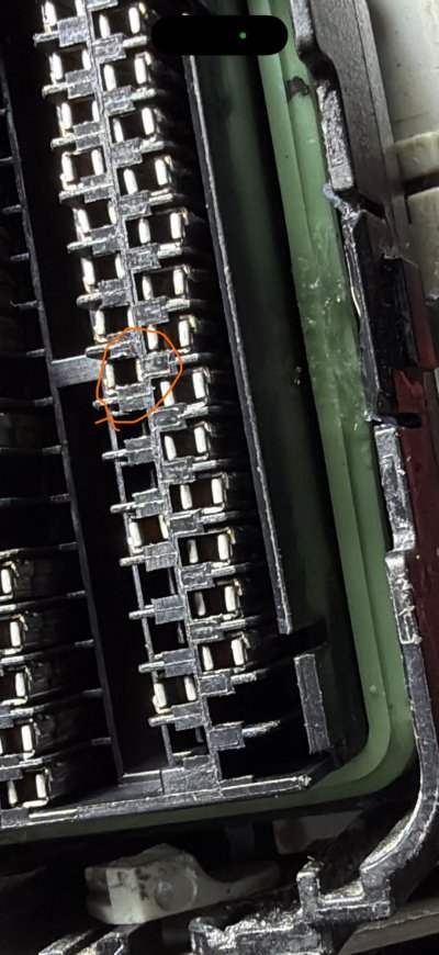
I received replacement PCM from Flagship programmed to my VIN. Lito supplied PATS programming. Hooked everything up and still have same problem. This is PCM connector with red plastic cover removed. I was not aware that came off. Circle is #25.
Before yesterday, in order to test for continuity, I had to use a piece of safety wire to fit in the small hole. This pushed pass the pin and touched wire making contact. With cover off, I can use probe from multimeter directly. I can also grab wire from behind. It fails the wiggle test. I believe the pin has a short, or broken wire.
How do I depin this, and is there a part number for the pin? I spent over an hour last night looking online. The only solution I found was going to a junk yard or buying used wire harnesses off EBay.

IMG_0585.jpeg
 

GlassTop09

Senior Member
Joined
May 24, 2019
Posts
1,407
Reaction score
881
Location
Farmington, NM
Check this video here for reference..............


Also, I highly recommend picking up a set of connector depinning tools (don't need to get the professional sets..........get the cheap sets usually strung together using a ball chain........) so you'll have them in hand to depin most any connector made........including Ford so good back up tool set to have......whether you have a jeweler's set of screwdrivers or picks in hand or not.

Brian covers most of the types of Ford connectors that are used on most Ford vehicles so you can get an idea of how to go about this.........but in the end practice will have to suffice........been there, done this myself.......have to finally figure it out where the inner locks are located within the connector body & what specific depin tool to use to unlatch it.

As for spare connector pins, your best source will be the Ford dealerships if no other source can be found...........just take a picture of the connector in question & where\what part\component it attaches to along w\ the usual vehicle ID info.........they should be able to get you the right replacement pins\pigtails for the connector.

Hope this helps.................

PS.........when you figure it out, please post your method as this specific Ford PCM connector I haven't had the task of depinning 1 at the moment. You also could hit up Matt Soppa @ Make It Modular for pointers as he regularly does this on the very connector you're looking to work on.
 
Last edited:

Laga

Senior Member
Joined
Aug 10, 2019
Posts
1,138
Reaction score
657
Location
Chicago
Check this video here for reference..............


Also, I highly recommend picking up a set of connector depinning tools (don't need to get the professional sets..........get the cheap sets usually strung together using a ball chain........) so you'll have them in hand to depin most any connector made........including Ford so good back up tool set to have......whether you have a jeweler's set of screwdrivers or picks in hand or not.

Brian covers most of the types of Ford connectors that are used on most Ford vehicles so you can get an idea of how to go about this.........but in the end practice will have to suffice........been there, done this myself.......have to finally figure it out where the inner locks are located within the connector body & what specific depin tool to use to unlatch it.

As for spare connector pins, your best source will be the Ford dealerships if no other source can be found...........just take a picture of the connector in question & where\what part\component it attaches to along w\ the usual vehicle ID info.........they should be able to get you the right replacement pins\pigtails for the connector.

Hope this helps.................

PS.........when you figure it out, please post your method as this specific Ford PCM connector I haven't had the task of depinning 1 at the moment. You also could hit up Matt Soppa @ Make It Modular for pointers as he regularly does this on the very connector you're looking to work on.
Thanks GlassTop. I had all ready ordered a kit of removal tools. I was hoping to find which one to use. I had a friend over today who raced and wrenched his whole life. He said this doesn’t make sense.
I have a Ford dealership very nearby and I’m going there tomorrow along with a service station that advertises electrical repairs. Hopefully Matt can offer some insight.
I will definitely post what happens. Maybe it can help MrPuffles too!

Edit: I have also posted questions and photos on three different subreddits on Reddit. Over 700 views and not one response. I guess this part doesn’t fail very often. Just my luck.
 
Last edited:

GlassTop09

Senior Member
Joined
May 24, 2019
Posts
1,407
Reaction score
881
Location
Farmington, NM
Thanks GlassTop. I had all ready ordered a kit of removal tools. I was hoping to find which one to use. I had a friend over today who raced and wrenched his whole life. He said this doesn’t make sense.
I have a Ford dealership very nearby and I’m going there tomorrow along with a service station that advertises electrical repairs. Hopefully Matt can offer some insight.
I will definitely post what happens. Maybe it can help MrPuffles too!

Edit: I have also posted questions and photos on three different subreddits on Reddit. Over 700 views and not one response. I guess this part doesn’t fail very often. Just my luck.
The reality is..........they do rarely fail..........you're just the "lucky lottery winner" in this scenario..........you've entered the rarity section of automotive TS\repairs where this is so uncommon that it will trip up even some well-seasoned techs........thus why it is so important to follow electrical TS procedures exactly & completely w\o shortcutting the steps.........even if you think you have figured it out already (remember the testing\verifying the pin #25 off ECU board for existence of the +5v MAF ref voltage before finally calling the ECU failed.....) because of what you've just experienced.

When dealing w\ electrical stuff, you'll find that a lot of stuff in the beginning won't make a lot of sense............but at some time later the light bulb will go off & then you'll be kicking yourself for making it seem to be so difficult........

Don't let this get you down either..........anybody who's worth their salt has already been here, done this at once thus has already learned the hard way to stop skimping procedure process\order. Real education of any sort is never a free ride.........you gonna pay for it in some fashion.......just make sure that it doesn't take you multiple instances of same type of failures to learn it.......then always try to pay it forward whenever you can.

Nobody is born w\ all of this knowledge........nobody! It all had to be learned from somewhere at some point in time.........some learn it earlier, some later.

On the depinning tools (depending on which you choose), some of these come in 2 sets--1 large clump & 1 small clump on separate chains. The smaller clump is the most commonly used set thus should help to cut down on finding the right 1 to use........so keep those separate from the rest to not get them mixed up.

At least now you know what's up...........the rest will come, just stay at it.
 

Support us!

Support Us - Become A Supporting Member Today!

Click Here For Details

Back
Top