Electrical help on 5r55s harness to Tr3650

TheCrowdPlow

Member
Joined
Jul 15, 2021
Posts
59
Reaction score
2
2010 Gt swapping the 5r55s to a Tr3650 and keeping the auto harness. I was following the guide that Anthony05GT made on the Stangnet forum and I had to stop at the part where he was saying which colored wires to cut and solder. On the big round 12 wire plug that inserts into the transmission and has rubber o-rings. Anthony says cut and solder together the red/light blue and white/pink wires. Well my plug is 11 wires and doesnt have either the red/light blue wire or the white/pink wire.
The 11 wire colors if got are;
1 green/blue
1 green/white
1 blue/orange
1 purple/white
1 grey/yellow
These 5 are on 1 side of the plug
On the other side of the plug are these 6
1 blue/beige
1 green/white
1 grey/beige
1 grey/yellow
1 yellow/beige
1 green/beige

Anyone know which are the 2 I'm supposed to cut and solder together?
 
Last edited:

bwilder10h

Junior Member
Joined
Jan 4, 2022
Posts
5
Reaction score
2
Following - I have a 2006 with 5r55 and a 30k 3650 sitting in the garage waiting to go in. The wiring harness is my last piece of the puzzle (minus the clutch purchase) and I want to see how using the stock harness works out.
 

TheCrowdPlow

Member
Joined
Jul 15, 2021
Posts
59
Reaction score
2
I'm not really getting any reply on multiple forums. I might just end up cutting the round 11 wire plug off, stripping the wires and just touching each one together one by one seeing which one allows me to start the car.
To my knowledge the reason for cutting 2 of them and soldering them together is what allows the car to start?
 
Joined
Sep 1, 2018
Posts
59
Reaction score
19
2010 Gt swapping the 5r55s to a Tr3650 and keeping the auto harness. I was following the guide that Anthony05GT made on the Stangnet forum and I had to stop at the part where he was saying which colored wires to cut and solder. On the big round 12 wire plug that inserts into the transmission and has rubber o-rings. Anthony says cut and solder together the red/light blue and white/pink wires. Well my plug is 11 wires and doesnt have either the red/light blue wire or the white/pink wire.
The 11 wire colors if got are;
1 green/blue
1 green/white
1 blue/orange
1 purple/white
1 grey/yellow
These 5 are on 1 side of the plug
On the other side of the plug are these 6
1 blue/beige
1 green/white
1 grey/beige
1 grey/yellow
1 yellow/beige
1 green/beige

Anyone know which are the 2 I'm supposed to cut and solder together?

Quick question, did you pull some of the tape off the wires leading up to that connecter to verify colors? If not, do so. The wires right at the connector tend to get discolored due to road grime, etc...I'm trying to find the connector/wiring diagrams for the 10 now. I have diagrams for the 06 but the colors are all different for that plug.
 

DieHarder

Senior Member
Joined
Nov 9, 2019
Posts
1,468
Reaction score
758
You're going to need to identify what signals those wires carry. Not just the colors. Once you identify them it should be apparent what needs to be done. Same as above colors are different from what you list. I believe the connector you're referring to is C167. According to below I'll assume he was talking to pins 10, 12 on C167.

Transmission controls are on pg 29-1: https://iihs.net/fsm/?d=40&f=Transmission Controls - 5R55S.pdf

Since connector views are not listed in the electrical manual C167 itself is wired as follows:
C167 - (Looking into the connector) Pin 1 is on the same side as the clip (on the left side) that locks the connector in. Pins are read from top to bottom
Pin Ckt/Color Gauge Function
P1 - Not used
P2 - 359/(GY-RD) 20 Signal Rtn
P3 - 1268/(RD-BK) 20 DTR Sensor, TR3A
P4 - 1144/(YE-BK) 20 DTR Sensor, TR1
P5 - 1145/(LB-BK) 20 DTR Sensor, TR2
P6 - 1143/(WH-BK) 20 DTR Sensor, TR4
P7 - Not used
P8 - Not used
P9 - Not used
P10 - 33/(WH-PK) 20 Switched power to starter relay
P11 - Not used
P12 - 33/(WH-PK) 20 Switched power to starter relay

Hope this helps.
 

TheCrowdPlow

Member
Joined
Jul 15, 2021
Posts
59
Reaction score
2
Pin Ckt/Color Gauge Function
P1 - Not used
P2 - 359/(GY-RD) 20 Signal Rtn
P3 - 1268/(RD-BK) 20 DTR Sensor, TR3A
P4 - 1144/(YE-BK) 20 DTR Sensor, TR1
P5 - 1145/(LB-BK) 20 DTR Sensor, TR2
P6 - 1143/(WH-BK) 20 DTR Sensor, TR4
P7 - Not used
P8 - Not used
P9 - Not used
P10 - 33/(WH-PK) 20 Switched power to starter relay
P11 - Not used
P12 - 33/(WH-PK) 20 Switched power to starter relay
My understanding of this is that there are only 7 pins/wires that actually connect? I know for a fact my auto plug has 11 wires and they all connect to a terminal. The plug has the potential to have a 12th wire/terminal connection but its just an empty slot. I can post a picture or 3 of you want?
 

DieHarder

Senior Member
Joined
Nov 9, 2019
Posts
1,468
Reaction score
758
I've never done the swap so difficult for me to say. You need to ID what the wires are for as well as colors. Maybe then you can figure out what the connections are supposed to connect together. I suggest researching the swap on this and other forums for someone with direct experience with the swap. I'd be glad to take a look at some pics but I have no experience with the 3650 as I have an '06 w/an 5R55s
 

TheCrowdPlow

Member
Joined
Jul 15, 2021
Posts
59
Reaction score
2
I believe the connector you're referring to is C167. According to below I'll assume he was talking to pins 10, 12 on C167.
Since connector views are not listed in the electrical manual C167 itself is wired as follows:
C167 - (Looking into the connector) Pin 1 is on the same side as the clip (on the left side) that locks the connector in. Pins are read from top to bottom.
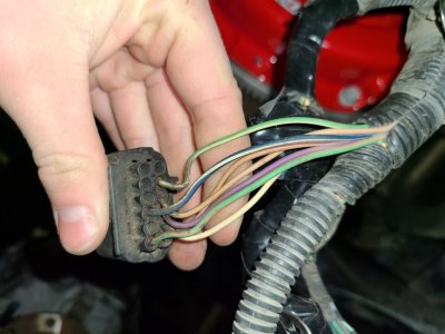
I'd this the connector? If so which way do I count the terminals exactly? Looking at the terminal side with the clip on the left side, do I count top to bottom left to right? Or down each column of 6 left to right?20220225_155705.jpg
The side of the connector with my 4 fingers is the side with the plastic clip. This is the connector that plugs into the shifter servo that slides onto the shift shaft sticking out of the auto.
I was looking at the wrong plug I think. I was under the impression that it's the round plug with 12 or 16 pin locations that slips into the body of the auto that I has to cut and solder the wires on.
 

DieHarder

Senior Member
Joined
Nov 9, 2019
Posts
1,468
Reaction score
758
Thanks for checking to verify....

Just took another look; it may be C199 that you want (16 pin round connector). It was hidden by another line on the drawings. Here's the breakdown of the pin assignments. Looking into the connector: Pin 1 is on the bottom (LB-PK wire); then pin 2 next to it. Should be fairly easy to ID pins by wire colors. If you're still not sure take a pic of it and I'll try to help.

Pin Circuit Color Function
1 966 (LB-PK) Pressure Control (PCB) solenoid B control
2 923 (OG-BK) Transmission Fluid Temp (TFT) sensor
3 391 (RD-YE) Voltage supplied in Start and Run (overload protected)
4 912 (WH-RD) Pressure Control (PCC) solenoid C control
5 236 (BK-LG) Shift solenoid D control
6 971 (PK-BK) Shift solenoid C control
7 Not used
8 Not used
9 Not used
10 Not used
11 925 (WH-YE) Pressure Control (PCA) solenoid A control
12 359 (GY-RD) Signal return
13 Not used
14 126 (VT-YE) Torque Converter Clutch (TCC) solenoid control
15 315 (VT-OG) Shift solenoid B control
16 237 (OG-YE) Shift solenoid A control
 
Last edited:

DieHarder

Senior Member
Joined
Nov 9, 2019
Posts
1,468
Reaction score
758
Regarding above - Truly cannot say which connector you're after.... Are you looking at plugs on the 3650 or the 5R55? Everything I've described is on the 5R55s. I don't have manuals for the the 3650.

If you're looking to patch together wiring to start the car you're gonna have to talk with someone with more knowledge of the swap. I haven't done it so I'm not sure which connector/wire you need to modify/connect to in order to start the car.
 
Last edited:

TheCrowdPlow

Member
Joined
Jul 15, 2021
Posts
59
Reaction score
2
it may be C199
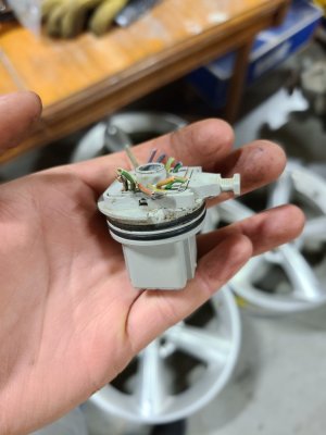
This one correct? If what those 11 pins out of the 16 you listed are correctly described it doesn't seem like they have anything to do with being able to start the car? It seems the actual 12 pin connector is the one that needs modification too to so the car can start.

Thanks for the help on these 2 plugs, I tried looking and couldn't find the right ones or they had a price listed to look at the wiring diagram.

20220225_160036.jpg
 

TheCrowdPlow

Member
Joined
Jul 15, 2021
Posts
59
Reaction score
2
If you're looking to patch together wiring to start the car you're gonna have to talk with someone with more knowledge of the swap. I haven't done it so I'm not sure which connector/wire you need to modify/connect to in order to start the car.
I'm trying all sorts of forums, most of them ate old threads that either no one seems to have a solid answer or has been dead for years.
 

redfirepearlgt

forum member
Joined
Mar 19, 2011
Posts
2,497
Reaction score
263
This may shed some light on your subject. Here is a snap shot of the C167 female connector pin layout straight from the 2005 electrical wiring diagram. Note that pin 10 is indicated as Rd/LB (red w light blue) and pin 12 is indicated as Wh/Pk (white w Pink). This is ultimately the circuit where the clutch engaged to start switch is. Below is the connector pinout for C167 from my 2005 wiring schematic as well as the wiring detail differences of the circuit between the two. After soldering pin 10 and 12 together you will also need to source out the shorting jumper which is where you will install the clutch engaged pedal switch. Likely up under the dash. Otherwise unless you are over say age 50 when cars did not come with these you will get a wild experience the first time you start the car in gear and forget to push in on the clutch pedal with it in gear. Hope this helps you.

8eq55uR.jpg

Z2sggPN.jpg


This should resolve your dilemma and allow the car to start when you complete the process. Wiring colors do sometimes change from year to year though the body does not. You would have to ask an IN-JUH-NEAR why they find the need to do that. Good luck. Please take a moment to reply if this works. Time was provided to help you out. Courtesy in return for others to also be able to use this if it is correct adn works in real world is appreciated by all.
 

TheCrowdPlow

Member
Joined
Jul 15, 2021
Posts
59
Reaction score
2
This may shed some light on your subject. Hope this helps you.
8eq55uR.jpg

Z2sggPN.jpg
oh man this is exactly what I needed, thank you so much. I don't think I'm gonna worry about wiring up the neutral safety switch at the moment. The 3 older dodge work trucks all don't have this and I'm very used to always pushing in the clutch before starting.
Again thank you so much, now I can do my soldering with tons of space before the transmission is in and install the trans. I need my trans installed so I can finish up the rest of the work on my car like putting the shifter in, routing clutch line, installing new motor mounts, replacing my header gaskets.
 

DieHarder

Senior Member
Joined
Nov 9, 2019
Posts
1,468
Reaction score
758
Apologies, didn't see the post above before sending....

Well, I looked at the electrical wiring diagrams again to try and get a better sense of what the interconnect was supposed to be for. Since you're using the old harness I noticed that the DTR is a sort of pass thru for 12v that's needed in order to activate the starter relay.

Refer to: https://iihs.net/fsm/?d=40&f=Starting System.pdf

According to the electrical diagrams C167 is the only place that needs to be connected as it's a pass thru from the BEC to the DTR and back to the Starter relay in the BEC (to start the car). Where to do that would be at C167 by connecting the wires for pins 10 & 12 together. Look at the manual ref above (top of pg - Right side).

DTR reference: https://iihs.net/fsm/?d=40&f=Transmission Controls - 5R55S.pdf
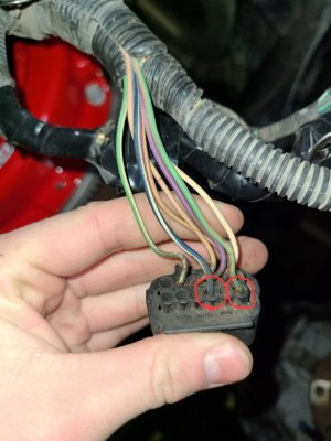
(bottom left of pg - Starting system (C167) pins 10 & 12. My manual says they're WH-PK however, according to the picture on your C167 connector those wires are Blue/White stripe (pin 10) and the Green/Orange stripe (pin 12).

That will provide 12v switched power to the starter relay. To check that everything works properly simply find a small jumper cable (w/alligator clips) and jumper those two wires together. If the starter turns over you've got it.
 
Last edited:

TheCrowdPlow

Member
Joined
Jul 15, 2021
Posts
59
Reaction score
2
For anyone else that is doing this on a 2010 auto wiring harness the 2 wires are gonna be dark blue & white/green & beige. They are the only 2 wires on that 6 pin side on the 12 pin connector.20220226_092659.jpg
 

TheCrowdPlow

Member
Joined
Jul 15, 2021
Posts
59
Reaction score
2
According to the electrical diagrams C167 is the only place that needs to be connected as it's a pass thru from the BEC to the DTR and back to the Starter relay in the BEC (to start the car).
yup, that seems correct, I was thinking if I really wanted to I could've just left my shifter actuator plugged in with it just permanently in park, but I would have to tuck it up beside the transmission somewhere. But we've got thus figured out now so I don't need to. Thanks so much again. Now the last part of the puzzle is just finishing it all up and figuring out who can refresh my pcm with a manual tune without forcing me to also buy a whole new engine too at the same time.
 

redfirepearlgt

forum member
Joined
Mar 19, 2011
Posts
2,497
Reaction score
263
One of those two color wires should be up under the dash with a jumper in place. The other goes to starter relay in the main fuse box (BEC) that activates the solenoid on the starter. C215 in the print is where the Clutch switch ties in. The pin twelve wire(green w orange) should also be seen pm in the bussed electrical center (fuse box under hood) on the starter relay at pin 85 (referencing the relay) or coming in connector C1035b E-10). If you wish to verify it, run a length of wire from pin 12 on C167 up next to the bus center. Pull the starter relay. With a multimeter you can check for continuity when you place the leads on the length of wire and slot 85 that one side of the relay coil plugs into. Make sure you do this with key all the way off. You should read less than 2 ohms. That will eliminate any doubt of the wire in question to jumper at the transmission. This has to be jumpered according to the prints regardless or the car will try to start. (no cranking). The shifter actuator will not help you with the trans not in place as the shifter provides signal to the trans to close that circuit with it in park/neutral as I understand it. Without the trans in place and retaining the shifter device in place the jumper will still have to be made between 10-12 on C167. make sure you heat shrink the solder jumper as well. Electrical tape will unravel, eventually exposing the bade solder joint and likely short the circuit to ground popping the fuse F2.21 in the smart junction box.

As for the shift actuator I used that connector on my 2005 to provide voltage and light dimming to a dash mounted gauge pod. There is ignition keyed 12vdc. ground, and panel light through the dimmer on that connector. It has no jumper in it on the manual shift models.
 

Support us!

Support Us - Become A Supporting Member Today!

Click Here For Details

Sponsor Links

Banner image
Back
Top