Diagram for Green Connector to Fuse Box?

NotQuik

I can't drive
Joined
Sep 2, 2007
Posts
2,705
Reaction score
2
Location
Central Florida
So long story short, I untangled some of the wires (spagetti) and I got ahead of myself and forgot to mark the first one and naturally didn't take a picture either. All the others are good so i'm hoping either somebody can point me in the right direction or post a picture of theirs to compare too. The one in question as far as location has the black box around it, the wire itself is red with a yellow runner.

BBDF262C-F6AE-45D7-BE2C-5ACC70E4AD72-5750-000003D183759D7C.jpg


556D2C90-BB2C-4578-BB1E-14B27C0239B2-5750-000003D2B43637A2.jpg


I found this one doing a google search and it's the best i've been able to get. So I wasn't sure if there was a difference between 05 and 07 which is what mine is. Looking at the picture it would be the top right hand pin, however it's a different color. It looks like a couple other pins are also different.

page-9


page-9


Any help would be greatly appreciated.
 

TexasBlownV8

Formerly TexasBlownV6
Joined
Apr 4, 2008
Posts
5,025
Reaction score
98
Location
Central Texas
That looks like the rear-most block (closest to the shock tower); if i recall, that's connector c1035b. The '05 IS DIFFERENT from the '07, so that picture is not going to show the proper wires in the proper locations.

You can start here and try to find what you need.
http://iihs.net/fsm/?dir=40

The locations in the block are numbered and lettered (A-F widthwise and 1-12 lengthwise).

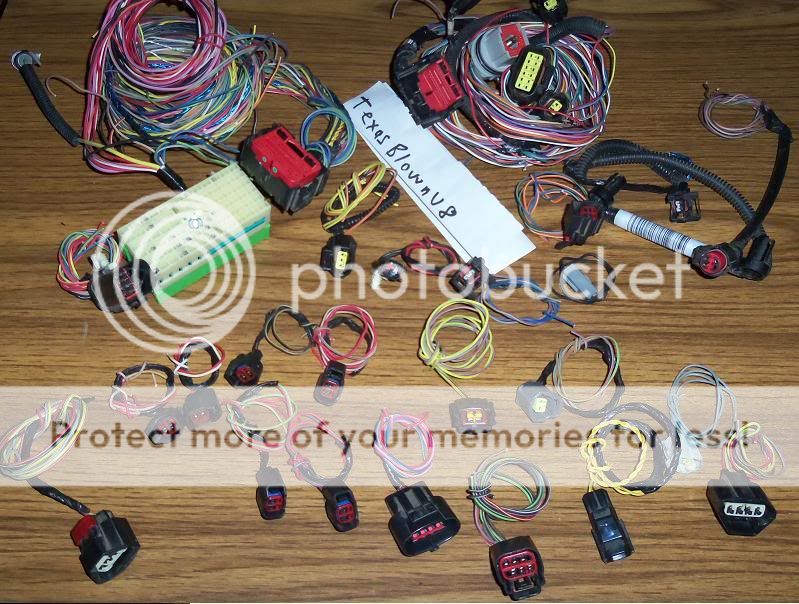
... here's a link to a pic where I show the pin-side of the connector; this is from a listing I have in the classified section for various connectors that are for sale.
connectors-tbv8.jpg


I can look to see if I still have that connector block and which wires are where.
 
Last edited:

NotQuik

I can't drive
Joined
Sep 2, 2007
Posts
2,705
Reaction score
2
Location
Central Florida
That one appears to be pinned differently from my 07 and the 05 I attempted to post. What year was that from Mike?

19cobra93, it's an 07.
 

TexasBlownV8

Formerly TexasBlownV6
Joined
Apr 4, 2008
Posts
5,025
Reaction score
98
Location
Central Texas
The pic I posted of the connectors are from a '05 and '06.

I thought you had a '05, my bad for misreading your first post :)
 

AnotherS197GT

Serial Valve Dropper
Joined
May 4, 2011
Posts
5,981
Reaction score
33
Location
USA
Here you go. This should be what you need. Sorry no picture.


Edit: Got the image working
 
Last edited:

NotQuik

I can't drive
Joined
Sep 2, 2007
Posts
2,705
Reaction score
2
Location
Central Florida
That's getting closer..

Mine has no A6 and no B2.

On that one it looks like E5 would be the one in question, however it's a different color wire and appears to be "transmission overdrive cancel switch signal" (I'm assuming that's related to an auto, mine is 5 speed). The RD-YE appears to be "voltage supplied in start and run (overload protected) which is A6 and on the opposite side of the grid on mine? I'll take a look at my actual fuse box tonight and see if A6 would line up with anything, just to double check. I am fairly certain I'm not that far off though.
 

AnotherS197GT

Serial Valve Dropper
Joined
May 4, 2011
Posts
5,981
Reaction score
33
Location
USA
If you give me your vin, I might be able to give you a better diagram. Idk though.
 

kevinatfms

EX-ford tech(6 years)
Joined
Jul 7, 2008
Posts
1,780
Reaction score
9
Location
MD
i have an 07 and 09 WSM/wiring books. shoot me a pm and ill set you up with PDF files of the connector pinouts that you need.
 

kevinatfms

EX-ford tech(6 years)
Joined
Jul 7, 2008
Posts
1,780
Reaction score
9
Location
MD
pm replied, 07 wiring diagram book at home and will bring in tomorrow. ill also check it out tonight when i get home too.
 

AnotherS197GT

Serial Valve Dropper
Joined
May 4, 2011
Posts
5,981
Reaction score
33
Location
USA
The same diagram came up.

What do you mean you have no A6 or B2? You are missing wires of that color?

Looking at the picture you took, you have a wire plugged into pin F5, which should be empty. I'd say that F5 wire is really your A6
 
Last edited:

NotQuik

I can't drive
Joined
Sep 2, 2007
Posts
2,705
Reaction score
2
Location
Central Florida
If you look at the pic of mine there is no B2. It looks like it shows B2 being white with light blue runner. Looking at the second picture I posted there is no white wire with light blue runner. All the other wires i'm 100% confident are in the correct location and I know I didn't forget any as I marked and removed them one at a time. I was diligent and angry with myself after realizing my initial mistake as soon as I removed that first pin. lol

I'm thinking the same about F5 and A6. I'll check the fuse box tonight and make sure there is something there and post back with what I find.

Here's a quick picture of the back of the fuse box where the connector plugs in, for what little that may be worth.

6D87F696-3410-43FE-B1BE-E479BC07C158-5750-0000045F31A8AF0A.jpg
 

kevinatfms

EX-ford tech(6 years)
Joined
Jul 7, 2008
Posts
1,780
Reaction score
9
Location
MD
i totally forgot the 07 WSM/IVTM on the kitchen counter this morning, i promise ill get it tomorrow!!!
 

NotQuik

I can't drive
Joined
Sep 2, 2007
Posts
2,705
Reaction score
2
Location
Central Florida
Alright, I looked at my fuse box and referenced what is on the opposite side the Pin.

A6 is A/C clutch

E5 goes to Engine #4.

For shits and grin's D5 goes to Engine #2.

I guess my confusion is that none of these quite match what the diagram above says...or maybe i'm simply overthinking here..Thoughts?
 

AnotherS197GT

Serial Valve Dropper
Joined
May 4, 2011
Posts
5,981
Reaction score
33
Location
USA
Diagrams are stupid lol. I'll pull an 06 diagram and see if its any different.
 

NotQuik

I can't drive
Joined
Sep 2, 2007
Posts
2,705
Reaction score
2
Location
Central Florida
I'm thinking out loud here so bare with me...

85 and 86 (A6 looks to go to 86) appear to be constant hot on the a/c relay, however looking at the diagram (http://iihs.net/fsm/?dir=40&viewfile=Fuse and Relay Information.pdf and Relay Information.pdf) it lists the wire as being BR/PK which isn't even a color in the harness.

The F39 (which appears to go to E5) appears to go to the brake pedal switch according to the diagram (http://iihs.net/fsm/?dir=40&viewfile=Vehicle Dynamic Systems.pdf Dynamic Systems.pdf) and calls for it being RD/YE which in turn is the wire in question...
 

Support us!

Support Us - Become A Supporting Member Today!

Click Here For Details

Back
Top