Crankshaft Sprocket and Key Failure

Joined
Feb 17, 2015
Posts
153
Reaction score
103
Location
Ellicott City, MD
Long story short, I was running Hot Rod Drag Week last week. Got a little overzealous with a trailer burnout leaving the first checkpoint and hit the rev limiter in second gear. An hour and a half later we were broken down on the side of the highway.

For context, I'm using an Eagle stroker rotating assembly, custom Bullet cams, TFS adjustable crank sprockets, and an Innovators West 8 rib damper.

After getting home and tearing things apart I discovered a few things.

1. The crank damper bolt was loose, like barely finger tight.

2. The rear cranks sprocket was fairly destroyed and the rear part of the crank key sheared off, so the driver's side camshaft wasn't rotating. The key ways on the other parts of the crank sprocket assembly and crank position reluctor wheel were beat up, but not destroyed.
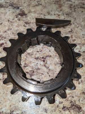
Sprocket and Key.jpg

3. A bit of the crankshaft was broken away where the key sheared off.
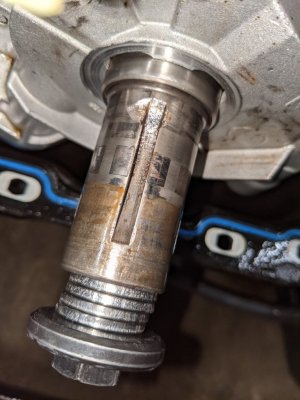
Crank.jpg

4. Evidence of piston to valve contact on the driver's side head, obviously. I consider myself very lucky that no valves broke off and embedded themselves in the pistons.
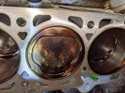
PTV Contact.jpg

I'm assuming that the crank damper bolt came loose and that reduction in clamping force allowed everything riding on the crankshaft key to destroy itself. Does this sound plausible? There's also the chance that the crank sprocket broke first and everything got beaten loose.

I'm looking at how to prevent this from happening again. I think the first point is to find an ARP bolt for the crank damper instead of the TTY bolt they provide. And to check that it's tight pretty religiously.

I'm also looking at welding the TFS sprockets this time around. It seems like there has been a lot of back and forth as to if this is necessary, but they seem to be the better option over adjustable camshaft gears.
 

RED09GT

Equal Opportunity Offender
S197 Team Member
Joined
Jul 17, 2009
Posts
2,630
Reaction score
488
Location
Kelowna, B.C. Canada
The pinning of the TFS Sprockets has been debated for a while now.

If the clamp load on the balancer is correct, this is what should be holding the sprockets in place and causing them to spin with the crankshaft.
If something goes wrong with the clamp load, the woodruff key then becomes what is spinning the sprockets rather than the stack of the sprockets, the reluctor wheel, and the balancer. Since the woodruff key barely has any meat under where the driver's side sprocket sits, a loss in clamping load leads to the keyway to shear off at that point.

If the gears are pinned or welded, the thicker part of the key saves it from shearing off if something goes wrong with either how the bolt is torqued or the TTY fastener loses its tension.

I have read of people using a stud that goes all the way back to the #1 main in order to eliminate the snout failures that happened with some of the terminator motors and this also makes sure that the woodruff key is not being relied on to turn the assembly.

I have the standard replacement ARP crank bolt since I don't have a blower tugging at the end of my crankshaft.

Sucks to see what happened to your engine. Did it take out all the valves on that side of the engine?
 
Joined
Feb 17, 2015
Posts
153
Reaction score
103
Location
Ellicott City, MD
Gotcha, that all makes sense. Sounds like pinning/welding is more of a fail safe than anything else. Based on the damage I saw the keyways will still be compromised if the damper bolt comes loose again.

I haven't torn the head apart yet, but at the very least I'm assuming all of the intake valves are bent. There's evidence of piston to intake valve contact on each cylinder. Full disclosure, my dad does head work, so it's not a huge deal to replace the valves lol.

What really gets me is how/why the crank bolt came loose. The cams have barely been in there a year, and I certainly remember torquing it correctly....
 

Midlife Crises

Senior Member
Joined
Jul 20, 2019
Posts
1,857
Reaction score
1,266
Location
Fairbanks, Alaska
My first question would be; Did you lap or hone the damper to fit the crank snout? If the damper is too tight on the snout the bolt can not achieve adequate clamp force. I made this mistake myself and found it before it exploded. My repair was to have the damper machined to 0.001 to 0.0015” smaller than the crank. This was also an Innovators West 8 rib overdrive damper. I used MMRs adjustable gears and after degree the cams I welded the gears together. The works was torqued to ARPs spec with an ARP bolt and red lock-tite. No problems and I have bounced off the 7,500 limiter several times.:driver:
 
Joined
Feb 17, 2015
Posts
153
Reaction score
103
Location
Ellicott City, MD
My first question would be; Did you lap or hone the damper to fit the crank snout? If the damper is too tight on the snout the bolt can not achieve adequate clamp force. I made this mistake myself and found it before it exploded. My repair was to have the damper machined to 0.001 to 0.0015” smaller than the crank. This was also an Innovators West 8 rib overdrive damper. I used MMRs adjustable gears and after degree the cams I welded the gears together. The works was torqued to ARPs spec with an ARP bolt and red lock-tite. No problems and I have bounced off the 7,500 limiter several times.:driver:

I know that we checked the fit of the crank damper when we put the engine together, but that was quite a few years ago. Couldn't tell you how much interference there was, I'll have to check!

I like your approach with the adjustable cam gears, especially considering that my crank snout is a little chewed up. Are these what you used?

https://www.modularmotorsportsracin...ge=product_info&cPath=4_5_50&products_id=1067
 

Midlife Crises

Senior Member
Joined
Jul 20, 2019
Posts
1,857
Reaction score
1,266
Location
Fairbanks, Alaska
Are these what you used?
Oh no. Those gears don’t work on the 3 valve. The gears I used are just like the set that failed you. I simply welded them together so they are a single unit. That way the inside gear doesn’t relay on the tip of the key to drive it. Insurance! Not hard to do. After degreeing the cams with the adjustable crank gears I noted the index marks on the gears and moved them to a spare crankshaft. Using a sleeve, washer and crank bolt to hold the gears firmly in place I welded them together with a TIG and mild steel rod. NOTE: The gears
shrink after welding and could require a puller to remove from the crank snout.
Sorry for not being clear the first time.
 

Latest posts

Support us!

Support Us - Become A Supporting Member Today!

Click Here For Details

Sponsor Links

Banner image
Back
Top