FRPP Hot Rod Cams

Dino Dino Bambino

I have a red car
Joined
Aug 11, 2014
Posts
4,120
Reaction score
2,023
Location
Cyprus
Ok I understand the RWD, AWD, FWD parasitic loss concept….

Didn’t know the % went down for new drivetrain but I guess they have gotten more efficient. I would love to see the stock RWD HP/TQ for a new mustang with 6spd vs 10-speed auto.

Those dyno numbers are already out there but there's a lot of variation depending on options, rear axle gear ratio, and which gear the dyno run was done in.
The best representation I can come up with for the 2024 Dark Horse & GT are as follows:

Manual: 10% at maximum TQ & 12% at maximum HP
10R80: 12.5% at maximum TQ & 13.5% at maximum HP

The automatics are particularly tricky because the dyno can't do a full rpm sweep in 1.00:1 7th gear and, depending on axle gear ratio, it might only be possible in 5th where the drivetrain loss is higher.

Fortunately we don't have that problem with our GTs because we can do a full dyno run in 1.00:1 4th gear.
 

GlassTop09

Senior Member
Joined
May 24, 2019
Posts
1,210
Reaction score
617
Location
Farmington, NM
An aluminium driveshaft will drop those numbers by ~1%
FYI......................all the dyno runs\sheet results of my car were made w\ a Ford Performance Aluminum 1-Piece Driveshaft installed........so going by your given numbers for driveline parasitic loss this really makes a 1-piece aluminum driveshaft usage vs the OEM 2-piece driveshaft design as far as rotational acceleration parasitic loss goes a statistical wash as the OEM 2-piece's driveline tube dia's are smaller than the Ford 1-piece aluminum driveshaft's tube dia (front section dia is 3" vs 3 1\2", rear section is 2 1/2" vs 3 1\2")......basic physics concerning rotational parasitic loss vs where the mass is located in relation to the C\L of rotation (or distance away from the C\L). The closer the mass is to C\L lowers the rolling moment of the part around its axis........meaning the smaller dia is generally easier to move initially. Mass has much less of an effect in this instance..........where the mass does have an effect is in inertial momentum......meaning the deceleration capabilities of the 1-piece aluminum driveshaft vs the OEM 2-piece driveshaft once both are spun up to speed.

This aspect of physics has been proven numerous times.................

I inadvertently tested this out by accident using my car set up\leveled on jackstands w\ rear axle on the jackstands, so the rear suspension was loaded so DL angles were set when I was chasing down the rear gear issues from the 1st initial install of the Richmond EXCEL 3.90 (3.89 actual 9 pinion\35 ring) gears before I swapped them out for the Motive Gear F888390 (3.91 actual 11 pinion\43 ring) gears. I had the Ford Performance 1-piece aluminum driveshaft installed & when I put the trans in 5th gear w\ engine at idle speeds, I noticed that the ECU had some trouble maintaining the engine idle speed steady\smooth after initial clutch engagement occurred......engine idle had a very noticeable up\down cadence in its idle speed control......meaning the engine was reacting to\chasing the aluminum driveshaft's rolling moment\inertial momentum characteristics. When I pulled this driveshaft out afterwards, installed the Ford OEM 2-piece driveshaft & w\ the car set up in the exact same position, ran it in the same 5th gear under same idle, the ECU quickly leveled out the engine after initial clutch engagement occurred & maintained a noticeably smoother\steadier idle speed cadence w\ very, very little change\oscillations.........meaning the engine was reacting to the OEM 2-piece driveshaft's rolling moment\inertial momentum characteristics as both driveshafts had the exact same loads\resistance exerted on both thru the rear axle gearing & suspension components\geometry angles, tire weights & same rolling moment\inertial momentum exerted from the tires\rotors\axles\gearing along w\ any rear brake caliper pad drag.......so the only items that were in actual differing affects to the engine's idle control was the 2 driveshaft's design characteristics..........neither driveshaft caused the engine to bog down noticeably lower than the other in RPMs off initial clutch engagement thus the rolling moments of the 2 driveshafts were essentially the same, but 1 driveshaft's mass had a noticeable effect on inertial momentum once both were spun up to idle RPMs......the OEM 2-piece driveshaft was the clear winner (or loser depending on POV) here & is a major reason why Ford OEM 2-piece driveshafts are much smoother\less prone to driveline vibrations\NVH transfer in operation as long as the other components in the 2-piece driveshaft (CV joints, center carrier bearing\hanger & front U-joint) are in good condition. From real world driving comparison for me afterwards, the difference was very obvious.............is the main reason why the Ford OEM 2-piece driveshaft is still installed under my Stang to this day (cruiser duty is my #1 priority) & the Ford Performance 1-Piece Aluminum Driveshaft is still sitting in my shed to be used as a spare.

Now if I were to get into HPDE circuit track racing seriously........................be a different conversation as in this type of environment, every advantage has merit, regardless of how large or small.

Where an aluminum drive shaft is also superior is due to the total measured mass\weight of the part vs the OEM 2-piece driveshaft.......thus the total overall weight\mass of the vehicle it is installed in vs the same vehicle w\ the OEM 2-piece driveshaft installed.......there is no question of its "superiority" in this instance, regardless of how the car is being used.

Remember, when the OEM 2-piece driveshaft is hung under the car, its total mass has no bearing on the rotational aspects of this driveshaft as most ALL of its total mass is supported by the chassis thru the center support bracket\bearing, w\ the rest suspended by the rear axle pinion & trans output shafts on roller bearings..........thus not in play to the engine's rotational TQ output........thus rolling moment.

This aspect\fact is very often left out of the discussion & not touched on\acknowledged.........................

Again, basic Mechanical Engineering 101.............but Marketing Strategies 101 along w\ basic Capital Consumer Economics has sold a bunch of these aluminum driveshafts...........myself included as I own 1................

So as far as driveshafts are concerned IMHO when talking dynos, this isn't a difference maker as dynos don't measure roller deceleration.......only roller acceleration.........so only falls within the margins at best........too many other, more viable variables exist to counter a driveshaft design whether OEM or aluminum.

This is why I put the word superiority in quotation marks............because variables do matter along w\ a person's POV & is the reason why dynos are always a hypothetical conversation\discussion........even in\with the best of intentions.

Of course, YMMV..............depending on your POV........

As far as getting my car dyno'd before the timing refresh\Hot Rod cam swapout, this may not happen as I definitely ain't going back to my local prior tuner & even remotely give him access to my car's OBDII port..........a good way to get my tune access locked out thru potential tuner retaliation using HPTuner's Tuner Lock feature (don't really know if he would do this or not....I can guarantee he can't if I don't go there & give him access) just to find out what she's putting down now peak to peak.............if I go to Albuquerque & get this done on a dyno that was different from the Mustang dyno used here locally, along w\ the elevation difference between the 2 areas (roughly 3,000') alone & the numbers came out higher or lower, I'll say it now that all this will be brought up at some time & point along w\ any other potential variable(s) that would\could make a difference.........during the discussion of the numbers.

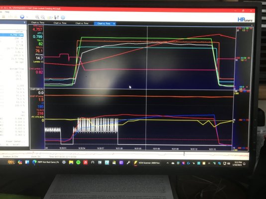
In times past, this would be of more importance to me to get a dyno run done & recorded, but since I now have HPTuners VCM Suite & MPVI2+ interface in hand & can actually see the calculated TQ outputs derived from my front-end tuning results (the EBTQ outputs are primarily calc'd off the accuracy of the upfront SD airmass tuning\calcs & back checked\corrected by MAF airmass tuning\calcs using the same fueling calcs\corrections & spark timing\VCT cam retard timing settings using the same trans gearing, rear gear ratio\tire size dia thus same NV calcs for driveline mechanical TQ (which the car's gross weight & any chassis drag coeff, tire rolling moments will affect) thru using the trans VSS RPMs output compared to the engine's RPMs output........the IPC Wheel TQ Error graphs showing me that the SD calcs are essentially in line w\ the MAF calcs so ALL tuning in my tune calibration is good\accurate enough to take the EBTQ outputs (mostly an engine flywheel centered calc that is based off real rear wheel characteristics......just not included in the EBTQ calcs) as a good indicator of what my car's capabilities are\will now do so I'm not nearly as interested in getting\paying for a dyno run\sheet now.......................only thing I need to do is to go out in Mexico & make a couple of 4th gear 2,500 rpm to limiter WOT hits to record it & finish it all up.........already have a "Dyno" math function set up in HPTuners VCM Scanner datalog charts that will use the ECU's calc'd EBTQ output data & calc the HP derived from it w\ 5,252 RPM cross point according to current engine RPMs so I can get the peak to peak TQ\HP output graph curves from this to serve my general purposes...........w\o paying anyone else.

Example provided below............................the red & blue graph traces in 2nd picture are "HP" & "TQ" from my VCM Scanner's "Dyno" math function. The mouse pointer line will give me the rest.........

I did this once early last year but didn't get to redline (was approx 320 RPM short......redline is set @ 6,500 on ETC as primary limiter w\ spark\fuel cut as secondary limiters to protect my timing chain guides, tensioners, phasers, OPG's & potential piston to valve clearance issues from any overrevs) due to me letting off throttle from my hood deflector shield pulling the plastic rivet clips out of the hood shield's metal mounting brackets & blowing over the car's roof at around 122 MPH at the time (3.91 gears\26.1" dia tires at 6,500 RPM redline 4th gear @ 130 MPH)........on less EBTQ output than now. The replacement hood deflector shield is now bolted to the mounting brackets using M8 x 16mm license plate bolts thru M8 windshield fairing nut clips using blue Loctite on bolt threads so she ain't coming off no more...............

So yes, she should get there a little faster now than it did then............this is where a Dragy would come in handy.........they're cheaper than a dyno session to boot...............modern technology put to good use.

Just being real about it all.
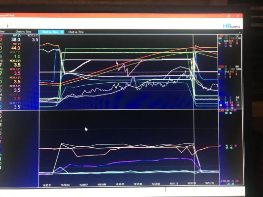
WOT Run 2-22-23 4th Gear 2,500 RPM to Limiter.JPG

WOT Run 2-22-23 4th Gear 2,500 RPM to Limiter Dyno.JPG
 

JC SSP

Senior Member
Joined
Nov 8, 2022
Posts
1,416
Reaction score
705
Location
FL
Thanks for the excellent right up. In short… this is the same concept on under drive pulleys for our engines which I have used with great success to this day. It’s untapped power that few people understand.
 

Dino Dino Bambino

I have a red car
Joined
Aug 11, 2014
Posts
4,120
Reaction score
2,023
Location
Cyprus
I remember my original stock driveshaft weighed 38lb and was 4" diameter over most of its length, while the aluminium DSS driveshaft that's on the car now is 3.5" diameter and weighs just 19lb. For comparison, the Ford Performance driveshaft weighs 23lb.
The reason for replacing the OEM driveshaft? A rumbling center carrier bearing.
 

GlassTop09

Senior Member
Joined
May 24, 2019
Posts
1,210
Reaction score
617
Location
Farmington, NM
Thanks for the excellent right up. In short… this is the same concept on under drive pulleys for our engines which I have used with great success to this day. It’s untapped power that few people understand.
Exactly..................speaking on this...............

Most have been conditioned to think these increase HP.........which is not exactly true as HP is calc'd from the exerted TQ amount that can carry over time & distance (or RPM's). Most also don't understand that a chassis dyno is the wrong tool to use to measure for the effects of undersized pulleys........an engine dyno is the better tool.............also don't understand that the measurement to look for is the amount of generated engine TQ decrease instead of increase as these pulleys don't increase TQ output of an engine........they REDUCE the amount of generated engine TQ needed to rotate the same accessories loading under the same engine RPM's (the reduced TQ amount is then calc'd into HP based on the same engine RPM's at steady state to expose this now reserved engine TQ output amount) vs using the std OEM engine drive pulley\WP pulley dia which reserves the extra generated engine TQ for use when needed later on when the extra TQ output is required\can be used (the main function of Torque Management in a computer-controlled engine management system or a MSD-type of distributor spark controlled carbed engine system) thus in reality is usually spread out over the engine's entire TQ band so how are you gonna find it on a chassis dyno which is affected by driveline parasitic power losses (among other variables) across the entire WOT pull to then calc a HP amount to an underdrive pulley set?

Let's see..........8-10 total HP increase spread out from approx 2,500 RPMs thru 6,800 RPMs................when the most likely area this extra reserved engine HP\TQ from underdrive pulley usage will show up is from off idle up to approx 2,500 RPMs.........where the chassis dyno isn't measuring at all.................and where the extra engine TQ output needed is the highest............thus is where TM will initially apply it.........if it is set up properly.............

But what do we know?................be better off if 1 took the car out on the street & used a Dragy to time the 60' launches to find it.

Mustang Lifestyle just recently put out a YouTube video of trying to measure this on his new DynoJet chassis dyno w\ a set of Steeda underdrive pulleys vs the OEM drive pulley\harmonic balancer & WP pulley on his VCT "straight up" locked out SBE 4.6L 3V engine running a set of Brenspeed Detroit Rocker NA cams in a New Edge Stang using its OEM ECU w\ its version of TM..........he couldn't see\find the claimed HP difference for these Steeda undersized pulleys thru his tuning...............go figure.

Entertaining video though...............while putting out misinformation that will potentially further confuse others.................

BTW..........I also love my set of Steeda underdrive pulleys that I installed as the very 1st engine mod after initially buying my Stang back in 10-2017......

:beer:
 

GlassTop09

Senior Member
Joined
May 24, 2019
Posts
1,210
Reaction score
617
Location
Farmington, NM
FYI........................

Here is a YouTube video of an interview w\ Billy Godbold @ Comp Cams that should clear the air on perspective as to why Ford gave the camshaft .006" lift adv dur seat-to-seat cam timing of both the OEM cams & the FRPP Hot Rod cams for tuning optimizing purposes using the SO ECU's OS DEPS vers of VCT coding...........the good stuff that points to what I've posted here starts around the 20:10 min mark onward & is in full agreement w\ Brian Tooley @ BTR Racing (but in this video Billy doesn't comment on which cam events are needed\used to create the cam chopping sound.........that would have explained why the FRPP Hot Rod cam's--or any chopping camshaft for that matter--EVO timing set at VCT 0* is important to then correct as soon as the engine is off idle--where the chopping sound is wanted but nowhere else--using VCT for regaining TQ output at low engine RPM operations...........

Enjoy!


GriffX

Senior Member
Joined
Sep 28, 2017
Posts
780
Reaction score
420
Thanks for your effort!
What do you think, the canned email tunes for the Hotrod cam, are they good, do they need further optimization?
If I decide to install such a cam, I can only rely on a email tune, but to get a unusual car for slow traffic is real I think?
 

GlassTop09

Senior Member
Joined
May 24, 2019
Posts
1,210
Reaction score
617
Location
Farmington, NM
FYI.........................

For context, please refer to posts #47 & #50 in this thread...............

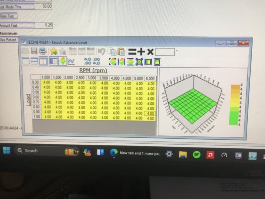
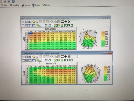
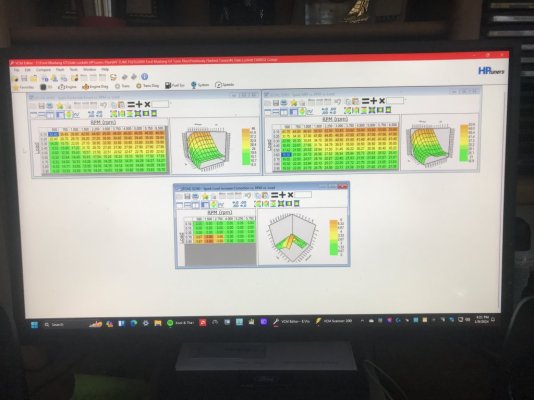
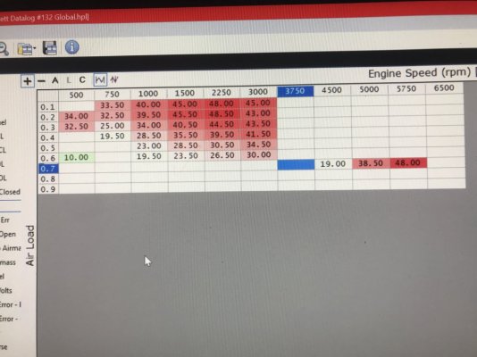
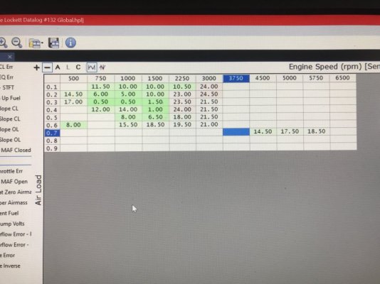
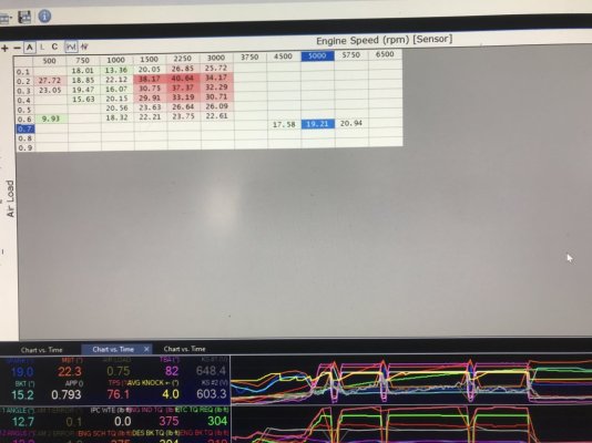
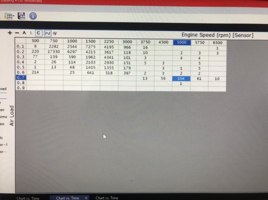
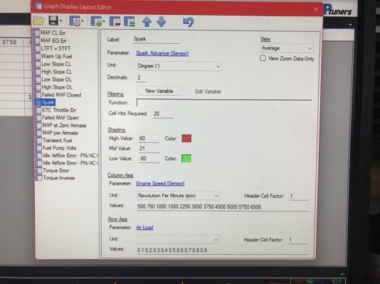
Here are some pictures of my 4.6L 3V V8's spark advance timing use I gathered from my HPTuners VCM Scanner's Spark Advance graph that I set up to use the 21* BTDC theoretical optimum max spark advance based off ignition\fuel burn time in crank degrees to optimize at max crank angle of 10* ATDC during power stroke for max TQ output........along w\ my optimized VCT cam retard timing map based off the same 10* ATDC crank angle by using my cam's (Lunati VooDoo #21270700 cams timing profile) .006" lift adv dur EVO timing w\ optimized VCT Spark Multi Adder map timing to offset the cam IVC timing (or dynamic compression) getting retarded\advanced at the same time thus is getting applied thru VCT operations as additional spark timing to the base BKT & base MBT Spark Advance timing map settings................

This data came from my last datalogged tune revision gathered this morning off a fresh flash into ECU\clean drive cycle w\ WOT run........meaning no prior ECU KAM generated data was available to skew any of this logged data......thus is reflective of my tuning setup thru the tune revision.........FYI.

As you can plainly see, this SO ECU is applying all avg spark advance timing used in very close conjunction to my optimized VCT cam retard timing mapping based off the optimum 10* ATDC power stroke TQ output crank angle of this 4.6L's displacement that Ford chose to use to model their OEM cam's cam timing profile--thus also the FRPP Hot Rod's same cam timing profile--so please note where in the VCM Scanner Spark Advance timing graph the ECU is applying spark advance timing that is in close agreement w\ Ben Alemeda's work to show the optimum crank angle thus piston position should be at the peak time of ignition\fuel burn time--thus max cyl pressure generation--he gave in crank degrees--31* BTDC.....................

Wherever this VCT cam retard timing is set closest to the max TQ power stroke crank angle of 10* ATDC, the applied total spark advance timing is also avg'ing closest to the optimum ignition\fuel burn time in crank degrees w\o cyl knock (the 31* BTDC spark\fuel burn timing comes out to be 21* BTDC actual spark advance timing from 10* ATDC position) thus also wherever the VCT cam timing is set the farthest away from this point, the spark advance timing used is also reflecting of it (taking advantage of the lower pumping losses AND the "extra" TQ output from 2 cyls force application to crank throws during 15* rotation past the 10* ATDC position before the lead cyl's cam EVO event occurs during the same power stroke cycle while also applying sufficient EGR to contain NOx generation well within EPA threshold specs for this '09 MY).

These results demonstrate the power of this SO ECU's Torque Management programming IF a tuner properly sets up ALL the supporting mapping that TM needs to operate to match up to ANY cam's .006" lift adv dur seat-to-seat cam EVO & IVC timing when it is properly lined up to this engine's optimum power stroke TQ producing crank angle for its displacement, which will duplicate at a minimum the OEM cam's TQ output during the same off idle, low RPM area as well as WOT..........as I've said earlier, from here on out, it is up to the cam grinders\engineers to optimally grind\position the rest of the cam's event timing to fall into line to gain the rest.......not the tuner.

Ford knew all this a LONG time ago..................they gave out the necessary info to achieve this w\ their Hot Rod NA camshafts (I found an article that showed where Ford was also trying to develop another set of cams based off these Hot Rod cams to go exclusively w\ FI applications, but they couldn't match the FRPP Hot Rod NA cam's mid-range\top end HP\TQ when run under FI thus they gave up on them & went exclusively w\ these FRPP Hot Rod NA cams for both NA & FI usage...........here: https://www.motortrend.com/how-to/mmfp-1109-3v-heads-and-cams-testing-on-the-port-side/ . Note that they said of these Hot Rod cams losing some low end TQ output when FI is used............not necessarily the case when they're used w\ NA configured engines that they were originally designed to be used with........when they're properly setup..........) but it is up to the tuners to understand, use\apply it.........IOW's the science.

Them lowly Ford engineers................................. Also, this old winning racer & NA-centered engine builder from the West Coast racing circuits back in the day giving out some knowledge over YouTube....................

Now on the Hot Rod cams\timing refresh upgrade work for those so interested...........I'm waiting on the last part of my EOP pressure "tap" setup to arrive any day now so that I can install an external EOP access tap so I can then use my EOP test gauge at will going forward & attach to EOP "tap" from up top under the hood instead of having to crawl under the car & R&R'ing the EOP switch to do this. The weather is getting warm enough recently for me to get under her & get this part done.

Once I get this all installed & get all the baseline EOP operating curves (cold start thru hot idle thru running operations) then it'll be on me as to when I choose to start\finish this timing refresh\Hot Rod cam install & tune on her. The tune calibration is already set up & optimized to the FRPP Hot Rod cam's .006" lift adv dur cam EVO & IVC timing thru VCT cam retard timing mapping (easy to do when you already know where the optimum TQ crank angle timing position is for the engine displacement) thus the rest of the tune calibration won't be very far out as it is already mostly optimally set off this crank angle positioning..........just will need to adjust slightly the VCT Spark Multi Adders timing & maybe some A\F adjustment if at all as the majority of all this will be following the Lunati VooDoo cam's path since both will be using the same optimized 10* ATDC engine power stroke displacement TQ crank angle positioning of this SBE 4.6L 3V V8 thus total spark timing is already optimized off it.

Enjoy!

PS edit---Since Ben Alameda lives in Las Vegas, Nevada currently but was prevalent on the SoCal West Coast running all types of fuels but mostly E10 91 oct pump gas.........which is currently what I'm using as the only other 91 oct fuel present is at 1 Sinclair station out of 1 pump pumping E0 91 oct for all the carbed classic cars in the Farmington Metroplex area (Farmington, Bloomfield, Aztec & Kirkland NM towns w\ Farmington as the central hub) @ 14.7:1 stoich (E10 91 oct @ 14.08:1 stoich)........so it stands to reason that his optimum ignition\fuel burn time in crank degrees would show to be this accurate in my car.

Final Knock Sensor Max Spark Advance Timing Map.JPG

Final Lunati VooDoo 21270700 Cams Spanish Oaks VCT Profile for BKT MBT Spark Advance Use in TQ...JPG

GlassTop09 Finished Optimized Spark Lead-In Accel Timing Maps Setup.JPG

HPTuners Ford SO ECU Highest Spark Advance Timing Used.JPG

HPTuners Ford SO ECU Lowest Spark Advance Timing Used.JPG

HPTuners Ford SO ECU TM Avg Spark Advance Timing thru VCT Operations.JPG

HPTuners Ford SO ECU Total Cell Counts for Spark Advance Timing thru VCT Operations.JPG

HPTuners Spark Advance Graph Setup.JPG

Lunati Voodoo #21270700.PNG
 
Last edited:

GlassTop09

Senior Member
Joined
May 24, 2019
Posts
1,210
Reaction score
617
Location
Farmington, NM
Thanks for your effort!
What do you think, the canned email tunes for the Hotrod cam, are they good, do they need further optimization?
If I decide to install such a cam, I can only rely on a email tune, but to get a unusual car for slow traffic is real I think?
GriffX, that would be hard for me to say w\ any integrity...........will greatly depend on the tuner doing the tuning.........

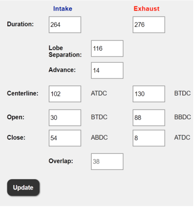
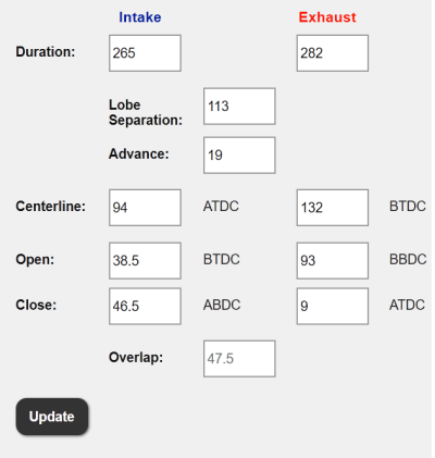
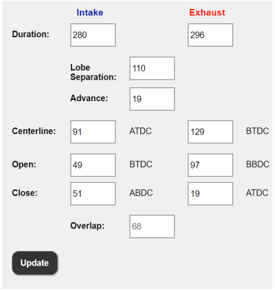
From what I'm seeing\learning from my own tuning.......it is very possible to get these FRPP Hot Rod cams to behave nice at low RPM operations, but if you really want the best chopping drop-in full VCT-compliant cam for all around operations, especially during off idle, low RPM operations........I'd suggest you go w\ Brenspeed's Detroit Rocker NA cams, if they're available where you are.............I'll post a copy of both these cam's .006" lift adv dur cam timing profiles for you to see where I'm coming from below.

Not trying to sell anything here, just providing information................the rest is up to you.

If I go by the several copies of other tuners calibration files that I have in hand that I got off the HPTuners Ford forums some time ago that are using these FRPP Hot Rod cams in these 4.6L 3V engines, well............................I'll leave it at this point.

If I were in your shoes & not interested\desired in setting up\learning to do your own tuning, I'd go w\ using Lito since he has a good proven track record of remote tuning these 4.6L 3V engines w\ these FRPP Hot Rod cams installed & has shown to be somewhat amendable to work w\ his customers to tune to their satisfaction. It's possible that Lito has been aware of all this science already...........after all, I read that he was employed in aeronautics at some time\point while running a speed shop\dyno as well as a drag racing team in Venezuela........

Best I can offer up on this at this time to be of any help to you concerning these FRPP Hot Rod cams.

Comp DetroitRocker NA Cams.PNG

FRPP HotRod Cams.PNG
 

GlassTop09

Senior Member
Joined
May 24, 2019
Posts
1,210
Reaction score
617
Location
Farmington, NM
If I decide to install such a cam, I can only rely on a email tune, but to get a unusual car for slow traffic is real I think?
Here is a YouTube video of this guy's 2005 GT street\race car fitted w\ an OEM SBE 4.6L 3V V8 running a set of these FRPP Hot
Rod cams w\ the usual complement of engine mods (CAI, mildly port-matched OEM IM w\ CMCV's removed, LTH's & matching midpipe thru a set of Pypes M80 mid mounted resonators w\ exhaust dumped just aft of the rear axle, running a set of FR 3.73 gears on a square set of 315\35\19's @ 26" dia) showing him driving this car around thru town & out on the freeways & back roads after reworking the exhaust.

His engine is showing\demoing no signs of any off idle, low RPM engine TQ loss while he's putting around while later on, he shows that his engine will absolutely break loose his 315\35\19's w\ ease off a rolling 1st gear thru 2nd gear to 3rd gear WOT hit w\o a lot of staging engine RPM prior doing this.........so there's someone out in SoCal that knows how to tune properly for these FRPP Hot Rod cams (he has a video of his car\this engine on the dyno w\ the dyno sheet results after doing all the engine rebuild work & vetting it out prior putting it on the dyno.........ironically at the very same race track that he frequently races at).

Enjoy!


Dino Dino Bambino

I have a red car
Joined
Aug 11, 2014
Posts
4,120
Reaction score
2,023
Location
Cyprus
Here is a YouTube video of this guy's 2005 GT street\race car fitted w\ an OEM SBE 4.6L 3V V8 running a set of these FRPP Hot
Rod cams w\ the usual complement of engine mods (CAI, mildly port-matched OEM IM w\ CMCV's removed, LTH's & matching midpipe thru a set of Pypes M80 mid mounted resonators w\ exhaust dumped just aft of the rear axle, running a set of FR 3.73 gears on a square set of 315\35\19's @ 26" dia) showing him driving this car around thru town & out on the freeways & back roads after reworking the exhaust.

His engine is showing\demoing no signs of any off idle, low RPM engine TQ loss while he's putting around while later on, he shows that his engine will absolutely break loose his 315\35\19's w\ ease off a rolling 1st gear thru 2nd gear to 3rd gear WOT hit w\o a lot of staging engine RPM prior doing this.........so there's someone out in SoCal that knows how to tune properly for these FRPP Hot Rod cams (he has a video of his car\this engine on the dyno w\ the dyno sheet results after doing all the engine rebuild work & vetting it out prior putting it on the dyno.........ironically at the very same race track that he frequently races at).

Enjoy!

The first of the four dyno graphs I posted earlier belongs to that car and it was tuned by Lito:


The Hot Rod cams do their best work from 3500-6000rpm. Below 3000rpm they're pretty soft and down at least 20lbft compared to the stockers. That's why you need the extra torque multiplication of 3.73 axle gears at a minimum to compensate.
 
Last edited:

GriffX

Senior Member
Joined
Sep 28, 2017
Posts
780
Reaction score
420
Thanks!
The Ford cams are more often to get here for around 900 and the Detroit Rockers I would have to import myself for 1100.
I analyzed some mail-in-tunes for my supercharged Mercedes and they did only the minimal necessary changes not to blow up the engine, very disappointing.
 

GlassTop09

Senior Member
Joined
May 24, 2019
Posts
1,210
Reaction score
617
Location
Farmington, NM
Thanks!
The Ford cams are more often to get here for around 900 and the Detroit Rockers I would have to import myself for 1100.
I analyzed some mail-in-tunes for my supercharged Mercedes and they did only the minimal necessary changes not to blow up the engine, very disappointing.
Ok then that makes sense..........so it would seem that these Ford Hot Rod cams are a very popular cam choice for these 4.6L V8's in Germany thus exist in enough volume to have a lower price as well as availability.

I can relate to how you feel..........................
 

GlassTop09

Senior Member
Joined
May 24, 2019
Posts
1,210
Reaction score
617
Location
Farmington, NM
FYI...................................

Please refer to pg 1, post #17 in this thread then watch this YouTube video I just put together to go along w\ this:

After this I'll digress from any further conversations concerning off idle, low RPM TQ loss using a WOT dyno sheet evaluating a Ford 4.6L 3V V8 using VCT.

Enjoy!

The first of the four dyno graphs I posted earlier belongs to that car and it was tuned by Lito:
Now on this point alone I'll say you're correct as I forgot that at the end of his video, he did say that Lito tuned it.


Dino Dino Bambino

I have a red car
Joined
Aug 11, 2014
Posts
4,120
Reaction score
2,023
Location
Cyprus
Unfortunately a WOT dyno sheet that begins at 2500rpm doesn't convey:

1. Rwhp & rwtq below 2500rpm at WOT.
2. Rwhp & rwtq at part throttle.
3. Other aspects of engine performance such as drivability, idle quality, fuel economy, and emissions.

The tuner can make a huge difference to all of the above.
It's a complicated enough process on a 3V that has variable ICA/ECA but only a SOHC per bank with a fixed LSA, but it's even more complicated on a Coyote with DOHC and a variable LSA as well as variable ICA/ECA. Phaser limiters or lockouts certainly make the tuner's life easier!


@GlassTop09 I truly admire your dedication and determination plus all the hours you've spent optimizing your tunes. You're an inspiration!
 
Last edited:

Support us!

Support Us - Become A Supporting Member Today!

Click Here For Details

Sponsor Links

Banner image
Back
Top