You are using an out of date browser. It may not display this or other websites correctly.
You should upgrade or use an alternative browser.
You should upgrade or use an alternative browser.
FRPP Hot Rod Cams
- Thread starter GlassTop09
- Start date
GlassTop09
Senior Member
FYI………….
From looking at the picture of my new VCT cam retard timing map using the 10* ATDC power stroke positioning TQ leveraging pattern in post #8 in this thread, I just now see another area in this map that I can improve low end TQ acceleration output from any camshaft used even more…….can’t explain why I didn’t pick up on this before now, but I see the potential now.
Will post pictures of all this once I get this setup, tested & recorded for verification…………….should be an easy result to get.
Yes, I’ve been told by a lot of folks in my prior profession that I’m a well whisperer……..mind never shuts down & always doing critical/computational thought process…..even when asleep.
Since I woke up at 3:45 hrs MT to go sit on the throne & this is when this realization came to mind, I guess they were right……..
GlassTop09
Senior Member
Thanks……..I’ll look into this when I get back home!Just remove everything behind the question mark in the YT link and the videos run.
GlassTop09
Senior Member
Most likely spring ATM due to winter closing in……but all the tune optimization patterns can be done/finished using my Lunati cams as the base changes will apply to any non-OEM camshaft’s .006” adv dur IVO, IVC, EVO, EVC, OL, valve lift profile…….only need to adjust per any differences in these camshaft’s cam timing profiles then everything else will fall in line……..so essentially am building a base file to incorporate all of these optimizations along w/ instructions to make it easier for others to use all this until they can get a handle on this to then take further steps if desired.Ahhh the bathroom epiphany.
When are you installing the Ford cams?
Kinda what you were asking for………
Dino Dino Bambino
I have a red car
So, as soon as this cam EVO timing point is realigned to the crankshaft 80* BBDC, all this stops & reverses back to optimal TQ leveraging along w/ optimal intake air charge fuel atomization/swirl/cyl fill velocity…..restoring max TQ output potential instantly…..only will need to apply a VCT spark multi adder to offset the amount of cam IVC retard to restore (or increase if desired) the cyl pressure loss to complete full recovery.
This where you're limited in what you can do with the 3V cam timing as I mentioned earlier.
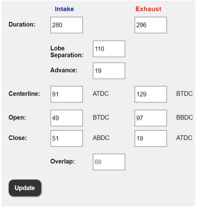
Since the lobe separation angle is fixed (OEM cam is 114.75 degrees, Hot Rod cams is much tighter at 110 degrees), advancing the exhaust valve opening also means you advance the intake valve opening to the same degree. The same also goes when you retard the cam timing.
By contrast, the Coyote has independent intake and exhaust cams thus allowing the lobe separation angle to be varied. Widening the LSA allows the exhaust valves to open earlier relative to the intake valve opening and reduces valve overlap, while tightening the LSA has the opposite effect. This gives a much wider range of cam timing adjustability and thus allows the Coyote to rev higher and still have good low rev torque with a smooth idle.
Unfortunately with the Hot Rod cams you're stuck with that 110 degree LSA so you're also stuck with the same massive 68 degrees of valve overlap. Therefore you can't widen the LSA to reduce valve overlap in order to get a smoother idle (not that people want that from HR cams) and more low rpm torque. The only tool you have for increasing low rpm torque (apart from playing around with spark timing and fuel) is to advance the cam timing, and you can only go so far with that before you run into the potential problem of the piston hitting the intake valve as it opens towards the end of the exhaust stroke. The HR cams already have the earliest IVO of any 3V cam at 49* BTDC and this is largely responsible for the large valve overlap (EVC is the same 19* ATDC as OEM cams). They also have the earliest EVO at 97* BBDC which hurts low rpm torque as it bleeds off cylinder pressure earlier in the power stroke.
You've taken on quite a challenge!
U got links to the u tube url for these 2 x video's ?FYI.................................
Here's a couple of YouTube videos of an interview w\ 1 of the most prominent cam manufacturers in the performance business. A lot of folks doing tuning need to really listen to this guy...............you'll definitely gain some much needed knowledge that undercuts a lot of the going stated "talk" put out. Don't get caught up in the fact that he chose to specialize in GM products.........the majority of his knowledge spans across any ICE design.....
Enjoy!
PS edit--For some reason these 2 videos won't show up here but they are available on YouTube............................
GlassTop09
Senior Member
Ok, I'm back at home now.Just remove everything behind the question mark in the YT link and the videos run.
So......to understand what you've posted.......to remove everything AFTER the ? mark to unlock the 2 videos, correct?
GlassTop09
Senior Member
Last edited:
GlassTop09
Senior Member
Not working...............I even used the "media" icon in post header to insert the YouTube video url in (it says that YouTube media is allowed) but all I get is "This video is unavailable"......but they actually are available & will play under YouTube just fine......but not on the BBS.Yes, the plain link without anything after v=XXXXXX
If I remove the rest after the? mark & put the link in the post.............all that does is pull up YouTube but doesn't show any videos (the rest of the link after the? mark is the particular YouTube video ID info).
I tested several different YouTube videos & all came up the exact same way as described above so I don't know what's going on outside of there appears to be some coding set in this BBS that is blocking these videos from loading\running........especially when I used the BBS "media" icon (where YouTube video url's are supposed to be inserted to then be displayed\run within the post).
Sorry............seems that you'll have to go to YouTube ATM & punch in the search "HPTuners Tuning School" & look for 2 Skype interviews w\ Brett McClellan @ HPTuners interviewing Brian Tooley @ Brian Tooley Racing (BTR).........
Best I can do ATM...................
GlassTop09
Senior Member
FYI..................
My finalized plan for installing these Hot Rod cams is to do a full timing upgrade at the same time to take care of some false knock issues I'm seeing from my engine's VCT system operation that I believe is due to worn cam phasers leakoff while they are being dithered (seeing KS voltage signal tracing suddenly drop off from time to time across both KS mics then instantly recover thus is impersonating a sound sine frequency wave from EOP transfer from 1 side of cam phaser oil chamber vanes to the other side that the knock retard signal up\down avg'ing can't wash out thus the ECU thinks the engine is knocking & momentarily cut spark timing then recover it.....along w\ the VCT solenoids making noise driving the KS voltage signals higher when they're being dithered......especially at the beginning\ending of moving the cams off ECU command. Engine's got 171,125 mi on her currently to date on OEM factory installed chains, guides, tensioners, oil pump, cam phasers, crank sprocket & lash adjusters (have replaced both VCT solenoids w\ the upgraded design as well as all cam followers w\ the upgraded design after finding 1 of the original OEM design cam followers broken in 2 pieces from metal fatigue 3 yrs ago.......6 months after initial install of my Lunati VooDoo #21270700 cams).
So, all this is tentatively scheduled to get done in the spring when the weather is better for working outside..........got enough of working on this car during last winter fixing\resolving all the stuff to get to where it's at currently.
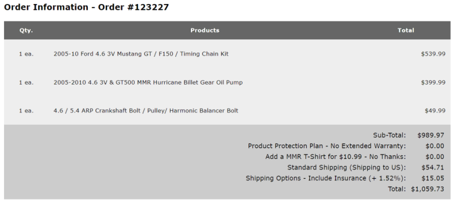
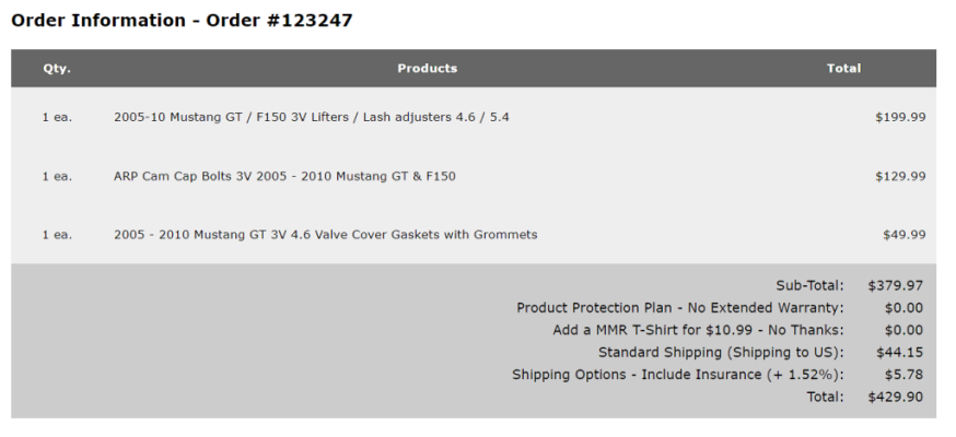
Plan is to pick up an 05-10 OEM Ford Mustang 4.6L 3V timing set from MMR (they replaced the plastic 3V chain tensioners w\ the cast iron 2V chain tensioners w\ the ratchets removed so they'll work correctly w\ the 3V timing setup) along w\ MMR's Hurricane HPHV oil pump (comes w\ billet oil pump gears installed, improved oil press control valving to increase oil volume flow & uses recessed Buna Viton O-ring seals to seal off to engine block mounting surfaces) over the winter months w\ all necessary gaskets & new ARP harmonic balancer bolt. Have read where the cam cap bolts are a TTY design thus should be replaced--at 89 in-lbs TQ spec--even though I've heard of no one informing of this prior reading this on MMR's web site......if so then I'll look into getting the ARP cam cap stud kit instead of bolts.
Should be good to go for another 170,000+ mi after this.................
Dino Dino Bambino
I have a red car
Fixed: 

GlassTop09
Senior Member
No problem.........will post this in full when I finalize it.Glasstop will you please post and itemized list of parts.
My 05’ has 120K and I foresee me doing a timing and oil pump (no cam) change in the future. Thx in advance.
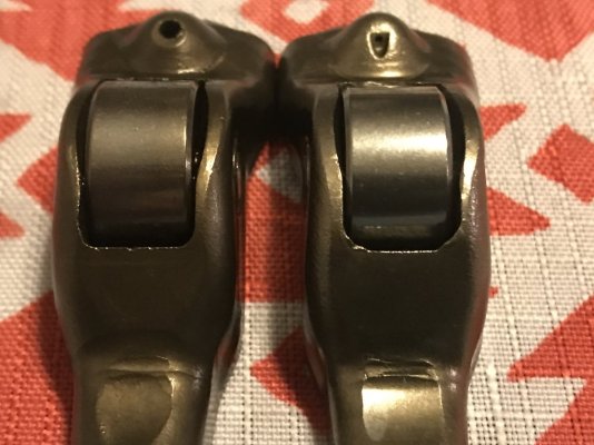
I will suggest that when you do yours, please seriously consider to replace all 24 of the original production design cam followers up front w\ the new upgraded design (FoMoCo 3L3Z-6564-A.....picture provided below, new design is the 1 on the right in picture.....Ford redesigned these for the 4.6L\5.4L 3V Mod Motors sometime in 2015 after recognizing the same type issues were occurring w\ the early 1st Gen Coyotes along w\ the myriad of cam follower failures w\ the 3V Mod Motors over their production history mostly due to lack of adequate oiling to the cam follower roller needle bearings but also due to sub par metal alloy used to build them.....mostly the 5.4L 3V Triton but the 4.6L 3V had its fair share as well) at a minimum along w\ the new upgraded design VCT solenoids (FoMoCo 8L3Z-6M280-B....Ford redesigned these after the 05-06 MY 3V Mod Motors due to excessively high rate of VCT solenoid valving getting stuck due to the valve-to-wall tolerances being too tight making them prone to light varnish buildup).
The lash adjusters are the only part that Ford never redesigned.......most likely due to very, very low rate of failure thus are very bulletproof as long as the maintenance is kept up, so you can most likely forego replacing these (thus can leave your cams installed on the cyl head) unless you desire to while you're in there (which then you'll have to remove the cams to do this).
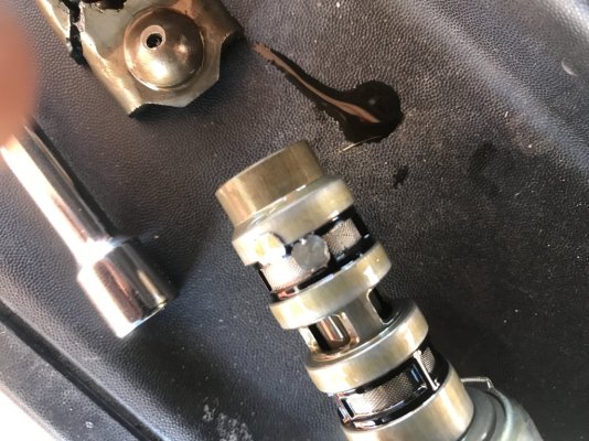
In my case, in hindsight I should've done all this when I initially installed my Lunati VooDoo cams back in 6-2019......but I didn't due to my visual inspection seeing no issues along w\ several stethoscope checks & hearing no issues prior to doing this work...........6 months later & then over 3 months afterwards of running checks to chase down a constant P0307 DTC misfire even after resolving the dielectric grease issue that WAS causing misfires.......then only after a follow up dyno run that found the VCT was slow to respond at low RPM's (lost some HP\TQ vs earlier dyno results) did I start to go thru the process of checking the VCT system (1st thing was replacing both VCT solenoids) is when I discovered the broken cam follower on 1 of the intake valves on #7 cyl (this was the cause of the P0307 DTC due to the cyl velocity variation on #7 cyl from the lack of cyl filling thru 1 intake valve vs the other cyls thru 2 intake valves so ECU recorded this as a misfire thus P0307 DTC....even though #7 coil\plug wasn't misfiring at all. Luckily nothing else was damaged.....also was the cause of the lost low RPM oil pressure due to the lash adjuster becoming fully unloaded lost oil control which then turned into Mount Vesuvius constantly spraying oil stream out of it). I also found some trash lodged on the bottom port of B2 VCT solenoid (looked like the round metal punchouts from the inner sleeve on the discharge side that supports the oil filter media of some brands of oil filters......not Ford filters as these are made by Purolator which uses a different designed inner sleeve thus none of this type of trash will exist, so I knew then that the prior owner of my ride used a different brand of oil filter than a Ford unit.....the only way this type of trash can get into the engine's pressure side oiling system) so you might want to pull both VCT solenoids & check for all this as well. I found out later on after resolving all this that there is a screen in the VCT solenoid mounting block (under an Allen plug right beside the VCT solenoid) that is designed to filter out any trash from entering the VCT solenoids that you might pull & check for any trash as well (which I'm gonna do myself, too......didn't find this out until I had her all put back together & running) while you're in there as well.
Thought I'd mention all this to you so you can consider adding all this to your list of checks while you're doing the timing job.
My advice is don't trust your visual inspection here.......just replace these parts up front........you'll be better off in the long run.
Hope this helps.
Last edited:
GlassTop09
Senior Member
Well........I've just finished doing all this & comparing the 10* ATDC power stroke positioning results to the same optimized tuning using the 17* ATDC power stroke positioning using the same Lunati VooDoo #21270700 cam's .006" adv dur cam timing IVO, IVC, EVO, EVC, OL, GI advance profile & I'll let the data speak for itself...............FYI………….
From looking at the picture of my new VCT cam retard timing map using the 10* ATDC power stroke positioning TQ leveraging pattern in post #8 in this thread, I just now see another area in this map that I can improve low end TQ acceleration output from any camshaft used even more…….can’t explain why I didn’t pick up on this before now, but I see the potential now.
Will post pictures of all this once I get this setup, tested & recorded for verification…………….should be an easy result to get.
Yes, I’ve been told by a lot of folks in my prior profession that I’m a well whisperer……..mind never shuts down & always doing critical/computational thought process…..even when asleep.
Since I woke up at 3:45 hrs MT to go sit on the throne & this is when this realization came to mind, I guess they were right……..
Mods..........is there a way to attach a folder to these posts outside of using something like PhotoBucket to display these files? .................as I have quite a few of them to list to back up my statements made here.
I'll provide a few of these below for viewing................
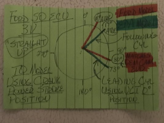
In short, I've found that if total WOT spark advance timing used is anywhere from 28*-32* on a 4.6L 3V NA engine..........you're over retarded VCT cam timing-wise (using a 17* ATDC model or greater either knowingly or unknowingly) & is losing max TQ output potential across the board......period. This is the only way this amount of spark advance timing can happen due to the amount of extra room created at the following cyl piston position later than 10* ATDC during the power stroke that is allowing this extra spark timing to be applied w\o knock.....but is not fully optimizing the available energy from combustion by not optimizing the cam's avg IVC timing curve thru VCT thus will come up short on max cyl pressure application due to piston top being too far down the bore from 10* ATDC at max cyl pressure generation from total fuel burn. I've also found that the cyl pressure generated is less stable due to the extra heat generated from the extra spark advance timing (causes the KS mic voltages to climb higher & are more prone to up\down fluctuations which will trigger cyl knock more easily when the cams are over retarded). You'll produce more avg TQ output when the following cyl's piston top during the beginning of power stroke is closest to 10* ATDC position of .03" from TDC & spark advance timing is set up\timed to generate max cyl pressure at this point........hands down. The only way to ensure that you're at this point is to use the cam's EVO timing to line up to the lead cyl crank throw of 80* BBDC during the power stroke by retarding the cam timing to match up to the crank throw timing point then stay within the 15* of spacing w\ the cam's EVO timing point between the crank throw's 80* BBDC to 65* BBDC area that will optimize the use of 2 cyls force during the same power stroke (use the outer 65* BBDC range for optimal cruising TQ output\emissions then shade towards the 80* BBDC point for max TQ output during off idle & WOT operations).
The 10* ATDC crank power stroke TQ positioning model IS THE BEST MODEL to use hands down for optimal TQ output across the board regardless of camshafts used.......from off idle thru WOT operations.........you won't\can't use anywhere NEAR the 28*-32* amount of spark advance timing listed above during WOT operations w\o inducing cyl knock..........you'll come VERY close to matching what the Ford engineers got when they did their WOT tuning.......between 18*-20* total spark advance timing using the OEM knock sensor Global Mode setup w\ the #2 cyl-to-#6 cyl KS mic assignment resolved & using the same OEM individual cyl sensitivity threshold map settings (I hit 18.5*-19* WOT total timing w\ all BKT Spark Advance Correction adders active & working using my Lunati VooDoo #21270700 cam's .006" adv dur cam timing profile vs the Ford tuned OEM tuning using the OEM cams using the same 10* ATDC power stroke TQ positioning in the same 18*-20* WOT area w\ same BKT Spark Advance Correction adders blocked out).
These results I got lining up w\ the Ford results are more than just a coincidence........they're actually verifying\validating the use of the 10* ATDC scaling while using a different cam timing profile from the OEM stock cams.......thus solidifying the actual power is in the crankshaft.......which is the common denominator between any cam's ground timing events profile created for this 3V engine's ECU\OS programming combo.
You will produce more avg TQ output while using less spark advance timing across the board thus increasing cyl stability using the 10* ATDC optimum power stroke TQ leveraging scale thus verifies\validates Ford's use of it to model\tune their camshafts for this 3V engine. In all the datalog clips I posted you'll note that I tried to set both the 10* ATDC clips & 17* ATDC clips using as close to the same engine RPM's to rep the same airmass flow potential thru the cylinders (thus the air pump scenario) so the resulting data will clearly show the differences created by the same cam timing profile being used at the differing piston positions created by the base 7*+ of crank throw spacing between the 2 "scales"........thus the reasoning as to why Ford listed the .006" adv dur cam timing data of the OEM stock cams vs the FRPP Hot Rod cams.........this is the only data that can be used to accurately set up VCT cam retard timing to give Torque Management the tools it needs to optimally manage engine TQ output..........you can quote all the .050" vs .006" lift, LSA, ICL, ECL, OL, DUR numbers all you want, the only numbers that matter for tuning purposes are the individual cam .006" adv dur seat-to-seat IVO, IVC, EVO, EVC numbers that were used to come up w\ the actual LSA, ICL, ECL, OL, DUR & GI advance numbers most quote to properly set up VCT & the knowledge of where the piston top is located within the cyl bore thru the specific crank throw degrees that are lined up to the cam timing seat-to-seat data to then know EXACTLY what will happen\take place within the cyl bore\CC during engine rotation to get the desired results.......otherwise you're only throwing mud against the wall until some of it sticks from a tuning perspective..........so if 1 isn't knowledgeable of the specific tune calibration's OS programming code line processing to then know how the ECU is gonna use all of this...........you're only throwing even more mud against the wall until something sticks.........but can't start to explain the how's & why's to verify\validate the results gained. Now if you do this long enough, you'll eventually work yourself into a pattern of some level of tuning efficiency (the true meaning of the term "experienced"), but I maintain if you actually learn all the science behind all this beforehand, you'll become a much better & more efficient tuner in a lot shorter time once you get the hang of the tuning software\interface operations being used to tune with.
Even a busted clock is correct twice a day............................doesn't make it a good clock to tell time off of it.
I'll digress at this point.....................
We'll definitely find out this coming spring when I get these Hot Rod cams installed & tune loaded up..........Lord willing.
I can also show you a couple of Forscan IM Readiness Mode 6 data scans in .txt format that shows this engine is meeting\completing all 7 IM Readiness emissions requirements w\ ease as long as the fuel tank level is between 15%-85% for EVAP test to run\complete.........even when hot lapped off back-to-back tune flashes that fully erase all this test result data so the ECU has to retest everything over again from scratch during the following drive cycle post reflash..........(but I can't post this in this posting due to using up all the available space allotted for attachments--max of 10 attachments per posting).
Enough for now...........................
Enjoy!
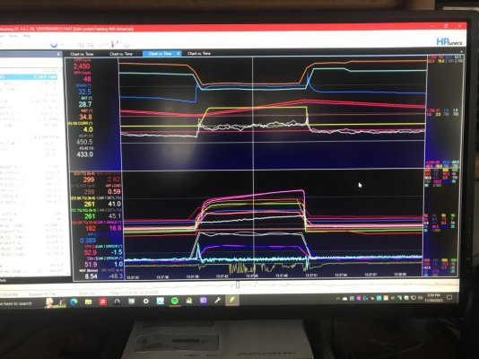
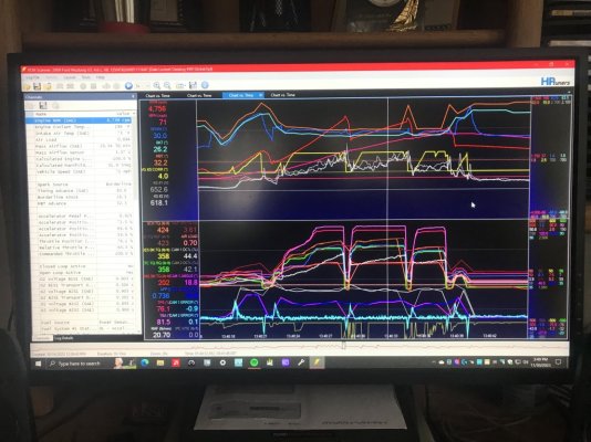
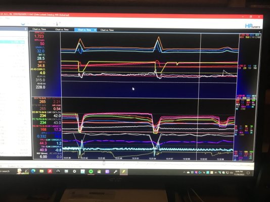
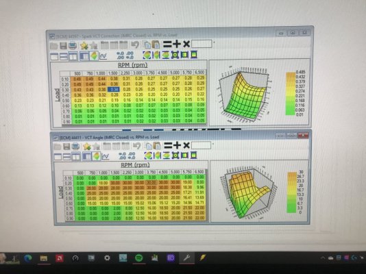
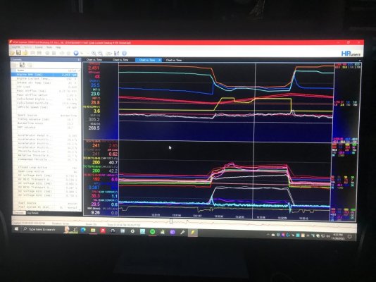
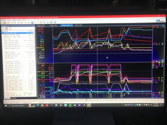
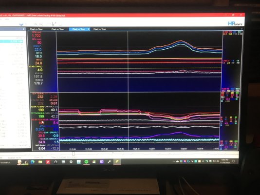
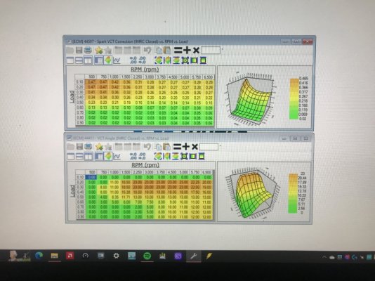
GlassTop09
Senior Member
FYI......................
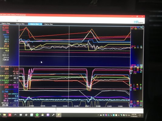
Please note on the Datalog #109 pic of WOT operations what looks like cyl knock in 3 places...........but I'll show you that there was only 1 place where actual cyl knock may have occurred.......the other 2 places are due to VCT operations thus are false knock...................
Looking at the 2 outer "cyl knock" occurrences, you'll note that there is no evidence of knock recovery stair stepping.......this is due to ECU's KS mic voltage onboard DSP not detecting the specific sound MHz oscillation pattern created from 2 flame fronts colliding w\ each other, but since the KS mic voltage did move in either an up or down motion vs the baseline, the ECU will start to cut the spark timing until the KS voltage signal recovers thus the ECU will quickly reapply this spark timing w\o creating a stair step recovery.......the cause is due to the VCT operations thru VCT solenoid dithering while moving EOP across the cam phaser chamber vanes to position the cams under spring loads while valves are under pressure from springs AND cyl pressure during the power stroke........not the cyl pressure\heat breaking down the fuel AKI rating thus is most likely a false knock occurrence.
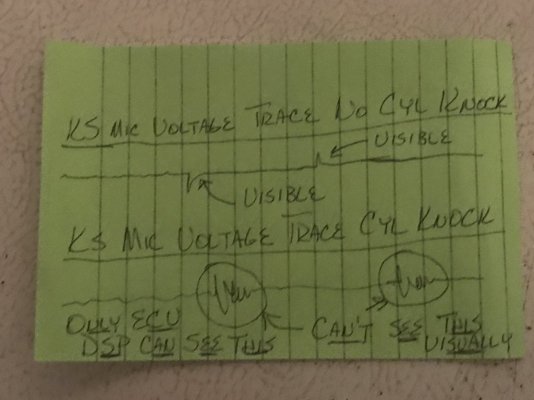
Now take your attention to the cyl knock marked by the mouse pointer line (a little hard to see but expand the pic) & you'll clearly see the knock recovery stair stepping being applied to this spark timing cut\recovery. This is proof that the ECU's KS mic voltage DSP detected the specific cyl knock MHz image created that matches up w\ the 91 oct fuel AKI when it breaks down from heat\pressure within this cyl's 3.55" bore area self-igniting & colliding w\ the intentional flame front created by the ignition thru the spark plug thru the KS mics AC voltage output tracing (we can't visually see this, but the DSP can after applying all the filtering settings) so this is most likely a real cyl knock event......made even more so thru me resolving the KS mic-to-cyl assignment correction between #2 & #6 cyls & replacing the old original KS mic harness that showed a weak #0 KS mic w\ a new replacement harness that corrected this issue as well, so now the knock sensor signaling\ECU deciphering outputs can be trusted to be more accurate.........you can see just how accurate from what I just described.
Provided a drawing of this KS mic AC voltage signaling below to give an idea of what this onboard sound DSP is looking for in the KS mic AC voltage output tracings.
Enjoy!


GlassTop09
Senior Member
FYI........................
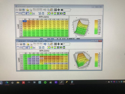
In the meantime, I've done some more modeling work & have finalized all this to now set up a baseline tune calibration file w\ all this work included to use as a "cheat sheet" going forward (I'll make a .pdf that will include pics of these specific files & their settings along w\ written instructions as to how to use them so all works as it is currently working now in my latest tune calibration--which will now definitely be the last for these Lunati VooDoo #21270700 cams & their .006" lift adv dur cam timing profile as there is nothing of consequence left to do......this last revision only finished optimizing the off idle\low RPM TQ output from the prior revision shown thru Datalog #109 clips in last posting once I finished my modeling & realized what Ford was doing w\ the WOT low RPM cam retard timing...........).
Provided below is a copy of this now fully optimized Lunati VooDoo #21270700 cam in-tune calibration Airflow\VCT\Configuration\Angle IMRC Open\Close Load cam EVO retard timing map settings along w\ the Spark Advance\BKT Corrections\VCT\VCT IMRC Open\Close Spark Multi Adder map settings that are also applied in tandem when ECU applies the VCT Angle Load EVO cam retard timing settings according to engine load & RPM's.......so these 2 maps work in synch w\ each other & are set up under BKT & MBT Spark Advance Corrections to mirror each other so ECU's TM is using this info to calc it's TQ calcs in real time thru MBT Spark Advance while ECU is applying it to engine operations in real time thru BKT Spark Advance so the calc'd TQ calcs will "match up" w\ the applied VCT cam retard timing\VCT spark multi adder timing.
The other pic is my proposed VCT cam timing setup to use w\ the FRPP Hot Rod cams when I get them installed........all based off the same modeling criteria used to set up the Lunati VooDoo VCT cam timing but used the .006" lift adv dur cam timing profile\WOT cam timing profile of the FRPP Hot Rod cams instead to determine the settings in these maps along w\ using my existing VCT Spark Advance Multi Adder map settings in tandem along w\ all the rest........just as I have done w\ the Lunati's.
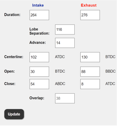
The modeling has shown that for WOT operations, the optimum VCT cam retard position is to be within 5* after passing the crank's 80* BBDC timing point to cam adv dur EVO timing synch point (for these Hot Rod cams, this is between 17*-22* cam retard range........which lines up w\ the FRPP Hot Rod cam's WOT max cam retard timing of 20* retard as given by Ford...........my Lunati cam's max @ 12* cam retard is in the ballpark......the #109 WOT pic shows the VCT cam retard at 11* off the mouse pointer line which is the same 3* past their 8*-13* cam retard range using the same 10* ATDC power stroke TQ leveraging model criteria in which you can see that this alignment is the best for max VE capacity thus HP\TQ output......the air load, MAF & EBTQ graph line data shows this when compared to the other pics using the 17* ATDC model at\near the same engine RPM's posted in prior posting (which I now know this 17* ATDC power stroke TQ leveraging model is better used w\ FI applications as it makes far more sense when boost is being used\applied........).
There is no "black magic" being used here as all cam manuf's cam grinds for this 4.6L 3V engine has all its optimizations.......including any GI cam advance timing.......already setup in the cam lobe profiles\cam IVO, IVC, EVO, EVC timing point profiles to work within the ECU's VCT cam retard range intended to be used (for full-VCT range this is 60* retard--thus why the piston has an exhaust valve relief cut into the dish crown, for limited-VCT range to use higher valve lift this is 20* retard, all other high lift cams have to use VCT lockouts which render VCT operations useless).........all GI cam advance\cam adv dur IVO point timing is spaced off the min piston-to-intake valve clearance specs thus is reason why this 4.6L 3V engine doesn't advance any cam timing ahead of "straight up" using the SO ECU's DEPS VCT system so whatever the cam manuf gives you to work with is all you got to use........sometimes it will need to be "balanced" between the cam's .006" adv dur IVC timing vs the same cam's .006" adv dur EVO timing vs crankshaft's 80* BBDC throw timing to achieve the optimum "net" low RPM\off idle TQ output........this is what Ford did w\ the Hot Rod cams by using the 7* of cam retard timing for WOT low RPM TQ output AND is where the use of the VCT Spark Advance Multi Adder Correction map timing Ford provided in the tune calibration\OS programming is critical to make up for the lost dynamic compression when the cams are retarded to maintain as much cyl pressure gain as can be retained to then make full use of the TQ leveraging during the power stroke. There is nothing said that this 7* cam retard timing can't be applied to the available HP\TQ side of VCT cam retard timing to boost off idle\low RPM TQ output........the cam-to-crank dynamics are exactly the same, whether this is used to help boost low RPM TQ output during WOT operations OR off idle, low RPM available HP\TQ output.........so I'm gonna prove this is true. The rest will come thru my supporting components that will complement the cam's large OL's purpose.......mainly the Kooks 1 5\8" LTH's optimized scavenging wave timing I have already installed.......which is why Ford also made suggestion to use LTH's in tandem w\ these camshafts to fully optimize their performance. All cam manuf's that grind cams for this engine have to abide\follow the Ford given specs for VCT usage when also grinding to achieve their intended goals........which means that no cam ground for this engine is optimized to be run at "straight up" cam-to-crank timing but optimized to run at a specific cam retard timing range\area that will provide the highest VE% efficiency thruput.........across the board.
This coding does work as Ford intended it to work..........the issue is hardly any tuners actually use it at all.......those who do use it leave it as Ford has originally set it up, which is counterproductive to how it really can\should be used IMHO & is why I took the time & rearranged all of this to work the way I see it being fully optimized thru TM & allowing all the BKT Spark Advance Correction Adder timing that is outside of being used thru TM (low IAT\ECT Spark Advance & the Transient Load Correction timing) to be applied when the conditions are met.
Also there needs to be a very clear line drawn between tuning a NA application vs a FI application & stop trying to use settings\modeling developed for tuning FI applications on NA engines............this is the main issue I've seen\witnessed from tuning my own 4.6L 3V engine that is killing NA engine available HP\TQ output & WOT HP\TQ output along w\ failing emissions for absolutely no reason........even when using non-EPA certified engine components..........my Stang is a prime example of this.
It's up to the tuner to find this optimized area.........either by constantly throwing mud at the wall until something sticks or by applying the science that was used to create it all in the 1st place. From my vantage point of view, a whole lot of mud has already been thrown against the wall......so I'll see\test what science can do w\ this.........
At least Ford did provide the tuner all the data needed to tune these to an optimal outcome..........up to the tuner to use it.
I chose the science & then deciphered what, how & why the creator.......FoMoCo.........did what they did then once learned\understood, I then rearranged it all to do what I want it to do using all the data Ford provided then tested\validated the modeling results............
We shall test to see what these FRPP Hot Rod cams will really do..............using the methods\modeling I've learned\developed..................
If the outcome goes anywhere close w\ these FRPP Hot Rod cams to what I'm getting now thru these Lunati VooDoo cams during off idle\low RPM operations, I'm gonna be a very happy camper indeed!
A dyno sheet or datalog pics just can't capture everything that is coming out of all this work..........
Now gonna start working on the .pdf file in the meantime.............................
PS edit (12-4-23)--I provided below 3 Forscan OBDII Mode 6 IM Readiness Check results (2 of them were off the back-to-back reflashes I made @ 11-30-23 to get to what the #109 Datalog operational data is reflecting thru emissions & the other 1 is from the last reflash @ 12-3-23 to finish fully optimizing the Lunati VooDoo off idle\low RPM TQ output. Especially look at the Catalyst #1\#2 test results as these are using my MagnaFlow #5461336 CARB-cert EO#D-193-140 TWC aftermarket cats that match this engine's VEI EFN# 9FMXV05.4VEK which are tested to flow as close to being equal to a straight piece of 2.5" pipe as can be done VE-wise w\ this 4.6L 3V NA SBE engine w\ all emissions tuning\DTC coding in the tune calibration left fully '09 GT period correct EPA-cert legal.


Attachments
Last edited:
GlassTop09
Senior Member
FYI.......................
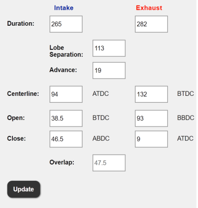
Here is provided below the .006" lift adv dur cam timing profile for the Brenspeed Detroit Rockers NA cams to compare to the FRPP Hot Rod cams same .006" lift adv dur cam timing profile for y'all's comparison purposes.................
As you can see, the FRPP Hot Rod cams aren't that much different as far in cam timing points & they both follow the cam timing criteria that gives both of them their idle chopping sound (the FRPP Hot Rods apply more EVO cam timing.....meaning opening sooner thus will sound more aggressive & visceral vs the Detroit Rockers thus closely mimicking the 60's era cammed big block V8's that most of us gearheads salivated over growing up) but also pay a price for that in lost idle power stroke TQ leverage vs DR's. HR's also lose the dynamic compression advantage to the DR's as well by quite a wide margin thru the cam IVC timing......4.5* worth thus these DR's will out TQ these HR's pretty much across the board. Both cam sets will breathe very well (due to the cam IVO timing set to allow the intake valve to open earlier in the exhaust-to-intake stroke transition where the cam OL is designed to take advantage of the exhaust scavenging velocities) but this is where the HR's have the 1 advantage over the DR's.........but the DR's will have a more efficient A\F mix cyl fill % vs the HR's thru the cam EVC timing (the piston will just be starting to move down the bore--at .02" from TDC--during the early intake stroke when the EVC event occurs so hardly no EGR occurs at idle thus increasing idle TQ output) whereas the HR's EVC event will be occurring at the same point as the OEM stock cams (at 19* ATDC where the piston will be at .13" down from TDC during early intake stroke......right at the same time that the exhaust scavenging positive wave timing pulse has made its way back from the OEM exhaust manifold collector back to the back side of exhaust valve just before it seats fully thus will bleed a little EGR back into the CC......this is by design from Ford.......how EGR % is administered thru VCT cam retard timing thus why no separate EGR valve\system is needed so in short, a HR cam is also tuned to provide some level of emissions compliance thru NOx control.......just like the OEM stock cams......FYI. This is where a set of LTH's w\ their longer tuned exhaust scavenging wave timing pulses is needed to offset this w\ HR's to improve the A\F mix cyl fill % & fully optimize the 68* of OL to achieve max intake port airflow velocities during the intake stroke cycle w\o the need of using CMCV's.......). Now once any 3V cam grind is retarded away from VCT 0*.......they ALL will have some amount of exhaust EGR flow entering the CC during the intake stroke thus will be administering NOx control by design.......and IS the main reason IMHO why CMCV's are installed & used during low RPM CL operations.......to provide good A\F mix during intake stroke cyl filling to achieve a clean, complete combustion which IS the goal to achieve max low RPM TQ output. The HR cams......when all is used, set up & tuned correctly.......provide the necessary intake port low RPM airflow velocities w\o using the CMCV's & is then why the suggested use of the FRPP IM & 62mm TB to go w\ the LTH's to make the HR cams "Power Pack" package. The LTH's......definitely a yes, but the other 2 components........well that's up for debate thus YMMV........more an aesthetics mod than anything else as the OEM 55mm TB & IM (when the CMCV's are removed) will move more than enough peak airmass flow for all street applications & some racing applications in NA engine configurations up to & including strokers & most all centri & turbo FI applications. Where the 62mm TB (or any larger TB for that matter) shines is during off idle\low RPM throttle response\acceleration performance.......hands down.......but they HAVE TO BE PROPERLY TUNED UNDER SD TB PTA\EA MAPPING TO REALIZE THIS POTENTIAL thru TM.......another area where this component has suffered thru poor tuning & not its design or purpose.......another subject for another day.......& in TVS\Twin Screw\Roots FI applications that use a draw thru MAF\TB air induction design where the larger TB PTA\EA area is served fully in both peak airmass flow AND off idle\low RPM throttle response performance.
Now........when comparing these DR's to stock OEM cams........I hate to have to say this...........the DR's will outperform a stock OEM 3V cam in every aspect of cam timing design........and sound much better doing it. If a DR cam set isn't outperforming a set of OEM stock cams it is due to the tuner tuning them........not due to the DR cam's .006" lift adv dur cam timing profile. The ONLY item that looks like a win for the stock OEM cams is the EVO cam timing point at idle......but when you also see the massive dynamic compression cam IVC timing advantage the DR's have over the OEM stock cams AND if the DR's are retarded just 3* to get their EVO to match the crank's 90* max crank throw length to offset the stock cam EVO advantage, the DR's STILL carry the dynamic IVC compression advantage vs a stock OEM cam thus what Brent White @ Brenspeed is saying about their Detroit Rocker NA cams is true........
You can argue all you want.............the facts stand for themselves. The tuner tuning them will be the difference maker.........
These DR's are the cams I really wanted to pick up..........but from looking at the HR's in comparison I see enough to work with to offset a lot of this between the 2 & get the HR's off idle\low RPM TQ output close enough to enjoy them & their better sound.......I also couldn't pass up on the price I was counteroffered on EBay as I couldn't find any DR's anywhere close to this price.......even on Brenspeed's web site.
Enough for now........................
Enjoy!


GlassTop09
Senior Member
Here ya go.............................provided below.Glasstop will you please post and itemized list of parts.
My 05’ has 120K and I foresee me doing a timing and oil pump (no cam) change in the future. Thx in advance.
I chose to go w\ MMR parts due to the advent of them modifying the HPHV Hurricane oil pump & the modified cast iron chain tensioners to use recessed Buna Viton O-ring seals that will provide a 100% positive & permanent seal to engine block facings so a piece of mind thing. I already have a full set of the upgraded designed cam followers in the engine so I'll reuse these but am gonna replace all 24 of the lash adjusters this round since the cams will be removed & these are the original parts along with the rest of the timing components. Already have the cams in hand.
Some of this is me planning for the future as well (plan is to build a low budget 10.5:1 CR hi compression stroker using this same engine as the base to build from) so you may do better price-wise when time comes for yours. The reason for the 2 invoices is due to me being hesitant to buy all in 1 shot at 1st since I have all winter to get it all.........but after later thought since making the 1st purchase, I said screw it & pulled the trigger on the rest..............
All just got shipped out to me today.............should have it all by Friday.
Anything else that pops up during the install this spring I'll deal w\ it as it shows up............so I'm fully committed to this project now!
Hope this helps.
Similar threads
- Replies
- 53
- Views
- 8K
- Replies
- 43
- Views
- 6K
- Replies
- 35
- Views
- 11K
Support us!
Support Us - Become A Supporting Member Today!
Click Here For Details


