FRPP Hot Rod Cams

GlassTop09

Senior Member
Joined
May 24, 2019
Posts
1,145
Reaction score
526
Location
Farmington, NM
Now gonna start working on the .pdf file in the meantime.............................
FYI........................

I have been working on this..............gotten up to 22 pgs (8.1 MB) to date & have made several updates after doing some proof reading to ensure that this .pdf's contents\instructions are legible & as easy for a tuner\individual to follow\apply as I can make it.........including pictures of actual tune calibration map settings, datalog inserts & hand drawings along w\ detailed explanations.

Every time I think I'm done, I remember something else that needs to be either mentioned, clarified or emphasized.............

Ongoing process but getting there slowly................

Also I'm seriously considering to start using MC 5W-50 FS engine oil (Coyote racing specs) in her after this timing refresh\cam install.........ran into a YouTube video of a guy who actually tracks a 3V & is running Mobile 1 10W-50 FS engine oil w\ fully functioning VCT active (also is running a set of FRPP Hot Rod cams to boot) due to the same reasoning as to why I'm looking at doing it...........his engine has >100,000 mi on it thus bearing clearances are perceived to be looser & is running w\o issues to date after also doing a full timing refresh job on it as well........mine is at 171,690+ mi...................

We'll see..................
 

JC SSP

Senior Member
Joined
Nov 8, 2022
Posts
1,079
Reaction score
466
Location
FL
The last time ran 20w-50 was in a big block Pontiac Trans Am in HS.

Consider putting a real oil PSI gauge and monitor accordingly.

Also consider sending your current oil for analysis and see what the results before increasing viscosity. I think Blackstone labs is a popular one.
 

GriffX

Member
Joined
Sep 28, 2017
Posts
536
Reaction score
183
I run GTL oil 5w40 only once in my 4.6 and got noticeable lash adjuster clicking during warm-up. Not sure if thicker oil is a good idea.

PS: Seen your order list, the balancer bolt 50 bucks???? Forged from Valyrian steel or what? :)
 

JC SSP

Senior Member
Joined
Nov 8, 2022
Posts
1,079
Reaction score
466
Location
FL
When I did my Steeda pulley kit I purchased a new ARP #156-2501 crank bolt & washer from Jeg's. $35.00
 

Pentalab

forum member
Joined
Mar 5, 2013
Posts
5,216
Reaction score
1,104
Thicker oil in a 4.6L is not a good idea. 5W-40 will cause severe grief. That's been well documented in the past. 10W-50 is way over the top.
0W-20 or 5W-20 if NA.....and 0W-30 or 5W-30 if a blower used.
 

GlassTop09

Senior Member
Joined
May 24, 2019
Posts
1,145
Reaction score
526
Location
Farmington, NM
The last time ran 20w-50 was in a big block Pontiac Trans Am in HS.

Consider putting a real oil PSI gauge and monitor accordingly.

Also consider sending your current oil for analysis and see what the results before increasing viscosity. I think Blackstone labs is a popular one.
Yes I'm aware that the old 60's era engines were all built using larger oil bearing clearance specs back in the day due to using mostly dino-based single viscosity engine oils, which required\allowed the usage of higher oil viscosities when the engine bearings were new\newish........also as I've noted in another thread.......oil viscosities play other parts in an engine besides lubrication.......also supplies crank\rod journal support to prevent actual metal-to-metal contact under higher loads........which is also why the operational engine oil pressures are an important factor to know........they determine the amount of EOP leakoff occurring between the bearings on the crank journals, rod journals & cam journals.....w\ this 3V also the cam phaser EOP leakoff rates & chain tensioner's intentional oiling rates vs leakoff rates if the gasket is leaking\blown.

Problem is............how many of us actually did this check to get the baseline cold, hot idle & operational EOP's when these 4.6L 3V engines were new then to have on hand vs now to determine any increase in operational EOP decline over time to use to make a better determination of all this? Yes, this is a very good measuring stick when the manuf's actually equipped these engines w\ fully operational EOP gauges back in the day that could give us ALL this data over time for those who actually paid attention to them.........but not these days.............especially if these vehicles are bought used......

All this does still apply to today's modern engines which are built using much tighter bearing clearances for engine operational efficiencies.........which also makes these modern engines even more susceptible to even smaller operational engine oil pressure changes thus the oil viscosities even more important in engine design to maintain proper supporting properties to prevent metal-to-metal contact.......thus IMHO should get more scrutiny instead of less........especially if 1 is to put these general production designed\built engines for public use under higher operational loads than they were built to normally operate under..........which is the overwhelming majority of us enthusiasts running these 4.6L 3V SBE V8's............if we were being honest about all this.

As far as checking\recording my engine's operational EOP, at this time, this would be a very good idea for me to do to get a base line using my engine's existing OEM 171,685+ mi oil pump pumping oil thru the same 171,685+ mi SBE long block before upcoming engine teardown for full timing refresh\FRPP Hot Rod cam install, to then make the proper judge of operational EOP thus bearing clearances condition after I do this timing refresh work (installing a HPHV oil pump along w\ 2 new chain tensioners which should change this scenario somewhat due to simple dynamics from applying increased oil volume output as well as pressure recovery up to either what the oil pump's internal bypass valve's spring....or the current actual running engine bearing clearances......will allow vs the std operational EOP given for a new 4.6L SBE long block.....operational EOP curve should show a net increase if all else being equal) to THEN make a determination as to whether to stick w\ 5W-30 FS, switch back to 5W-20 FS or move up to 5W-50 FS due to the current mileage (thus current bearing clearances from wear over time because I guarantee this engine has looser bearing clearances now vs when new) on my current SBE 4.6L long block.

This was how I was taught back in the day to determine this type of thing outside of educated guessing...........up to me to apply it though.

I understand why the oil analysis.........you'd be looking for any signs of engine bearing babbit metal in the oil.......this indicates some crank\rod bearing wear w\ this engine.......which is the natural find to have for a high mileage engine (even engine oil, no matter the viscosity, does impart some friction to components & bearing surfaces thus will cause some slight babbit wear......the intended component wear you want to see....nothing else). What you DON'T want to find is a high % of bearing babbit and\or any copper, aluminum or steel in the oil......this is indication of some more serious engine wear (crank\rod bearings have lost most\all their babbit thus have excessively worn due to lost crank\rod journal support thru the engine oil; cam journal aluminum metal wear in cam caps\cyl heads, timing cover wear from loose timing chains, worn thru tensioner metal supported chain guides, etc or serious wear that is causing steel shearing....spun bearings, cam lobe\cam follower roller shearing, etc) along w\ the oil stability\lubricity\breakdown analysis to determine if issue is due to either oil breakdown or excessive wear from high mileage\hard operating conditions causing loss of operational EOP over time thus loss of proper crank-to-journal cap\rod-to-crank journal component support.

But I most definitely will keep this in mind after all upcoming work is completed & proven reliable........

Basic IC engine wear dynamics that haven't changed since Henry Ford's time...................

From my scheduled oil change routines using the specific Ford MC 5W-30 FS oil that meets\exceeds this engine's API rated oil specs & judging by the color of it before I do get it changed.........I doubt the actual engine oil analysis is gonna tell me anything much more significant than what I can see using my own eyes as this oil overwhelmingly gets changed out far earlier than it really should be due to the car not being driven enough to routinely meet\exceed the full 5,000 mi between changes most of the time......changes are mostly me sticking to the TIME side of maintenance scheduling (according to the OM for this 3V using FS oil under high loads, 5,000 mi or 6 months whichever comes 1st thus at a minimum, 2 oil changes per yr unless I put more miles on or I'm pushing the engine harder due to WOT tuning) and, outside of my actual tuning routines performed to tune out WOT loads so I know what she's fully capable of doing, is not beat on at all (mostly cruiser duty as she's a '09 MY black-on-black Glass Roof version GT but when I want her to get up & go, I WANT her to GET UP & GO!) so my oil's color is mostly clean & is usually consistently just off the color it was coming out of the bottle so IMHO an oil analysis is kinda waste of money until I start doing something different w\ her........like hard running\racing or putting on more miles than time to determine oil change scheduling.........which TBH, will most likely never happen enough on a more routine basis.

Also just emptied my catch can last week (after 2+ yrs of continuous operation after the last time I emptied it......approx 3 1\2 oz of stripped\captured PCV oil mist) & can had absolutely no moisture\fuel intrusion into the captured PCV oil mist at all (milky oil from moisture is usually located on bottom of can tank from settling out of oil mist & oil will smell of E10 fuel fumes from excess piston ring blowby) so when I say she's running clean & efficient, this finding proves\verifies it.

The Hot Rod cam install is mostly for idle chopping sound to satisfy this itch I just can't ignore\resist anymore BUT they also can\will provide some good off idle, low RPM available HP\TQ output as well as WOT HP\TQ output as I've noted from all of my modeling work & learning just what\how\why Ford did what they did & why they provided the OEM cam's .006" lift adv dur cam timing along w\ the FRPP Hot Rod cam's same data so I have no doubts as to what the outcome is gonna be..........off idle & low RPM available HP\TQ output is gonna be better across the board than what most think it will be whereas the WOT side is gonna be mostly within the ballpark of what most have already seen on dyno sheet curves due to most all tuners already use the FRPP Hot Rod cams recommended WOT VCT cam EVO retard timing as Ford has provided thus any significant differences that do show up during WOT will be coming from mostly any additional optimized A\F tuning that can be applied (which in my case is near zero now......have checked\tested numerous times) or cyl knock tuning improvements found thru using something like a TunerNerd Pro engine cyl knock analyzer to further check\optimize the OEM Ford SO ECU's in-tune individual cyl sensitivity threshold map settings for further accuracy (find these in-tune cyl sensitivity threshold settings are still set excessively low for the 91 oct fuel's actual fuel AKI rating.......have already resolved some of this due to correcting the KS mic-to-cyl assignments between #2 & #6 cyls in in-tune knock detection mapping).

I'm also looking into the advent of being able to convert the 3V's current KS harness to use the better, more accurate & plentiful Coyote KS's as soon as I can find out if the actual specs to determine if the voltage\amperage outputs are the same\compatible between the 2..........the 3V's SO ECU\KS mics uses a 2V AC voltage generation spec which I think--don't have definitive proof yet--the Coyote's Copperhead & up ECU's also use but I can't find the actual AC current output specs to determine if the SO ECU knock DSP hardware\circuitry can handle this w\o issue......

If I find definitively that I can do this, I plan to also install some extra leads to these Coyote KS's connectors to facilitate hookup to a TunerNerd Pro cyl knock analyzer using these same KS's along w\ the ECU in the natural placement on the engine block under the IM w\o having to remove it so the TunerNerd Pro sees the exact same KS mic voltage generated signal outputs as the SO ECU's sound DSP does for true apples-to-apples tuning.

Just another side project I got going on in the meantime.................

FYI........................
 

GlassTop09

Senior Member
Joined
May 24, 2019
Posts
1,145
Reaction score
526
Location
Farmington, NM
FYI...........................

On p2, post #36 I posted some data of where I have gotten to w\ my car's tuning in relation to what is upcoming when I do the timing refresh\FRPP Hot Rod cam install & tune................

Well, here is some more data I'm providing below that will come into use w\ the Hot Rod cams as well as currently w\ my existing Lunati VooDoo cams..........

Was watching a YouTube video from Ben Alameda Racing titled "Additional Tuning after Dyno Testing?" where Ben was talking about how dyno tuning doesn't always translate to actual experience concerning off idle low RPM performance as most dyno tuners don't\can't account for any engine performance below 2,500 RPM's, especially when using aggressive camshafts.......got me to thinking about how this could happen & how to fix this w\ modern computer tuning so I went back looking at my tune files & this is what I found in my tune calibration then fixed in pictures & is currently working on below.

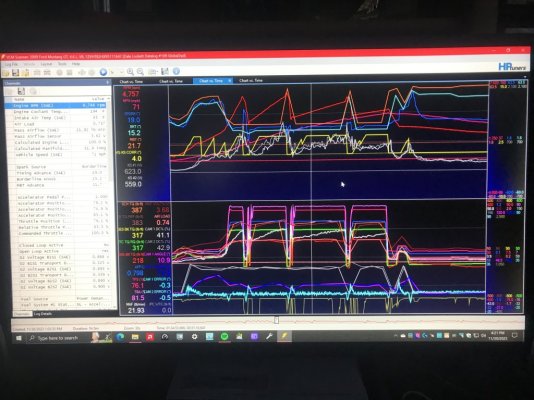
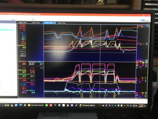
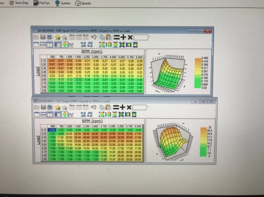
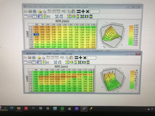
While doing this I also put in .25* more spark advance timing across .80-.90 load rows (this tightened up the timing difference between .70 to .80 row from .50* to .25* so ECU will tighten up on interpolation of any spark advance timing that falls between these 2 load rows) then loaded the revised tune file last Tuesday & ran drive cycle\WOT run.........engine gained 10 more ft-lbs of TQ output at WOT w\o cyl knock (went from 218 ft-lbs to 228 ft-lbs at the same engine RPM's in the same 3rd gear WOT loading to highlight the .5* of spark advance gain along w\ the running IAT\ECT differences to highlight the increases in MAF & airload from the 15*F of IAT difference (increased air density from lower running air temps @ 5,300' elevation).

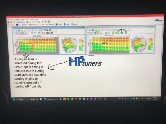
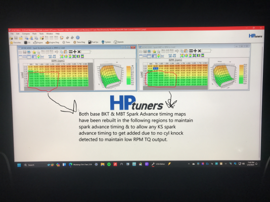
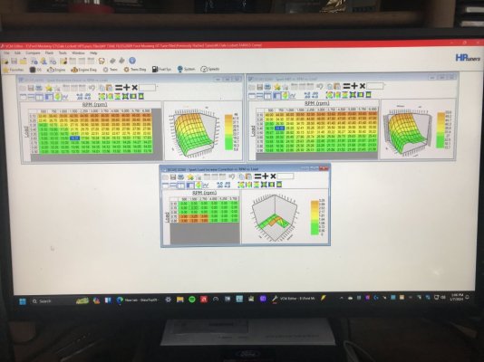
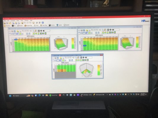
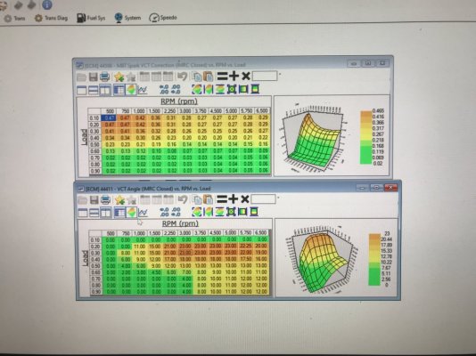
Now I am currently working on tuning in advanced lead-in spark advance timing during off idle, low RPM operations between 500-3,000 RPM's using these 3 spark timing maps (have noticed that this BKT Spark Advance Transient Load Correction map timing is getting added up front whenever the APP\TB TPS signal is increased past .30 load which activates the KS's & is interpolated between .30 load to .70 WOT load on) reworking the base MBT Spark Advance timing map between .30 load thru .90 load & from 500 RPM's thru 3,000 RPM's to facilitate the addition of extra spark lead-in advance timing to help up engine off idle, low rpm TQ output then applied vertical smoothing between .30 load to .70 load rows from 500 rpm's to 3,000 rpm's so this will get applied in a progressive manner according to the % of the APP\TB TPS getting applied (how ECU calc's predictive engine load under SD using the TB PTA\EA mapping in Electronic Throttle Control) so this will fit\work with the ECU interpolated Transient Load Correction setting application after .30 load row to .90 load row & current operating engine RPM's between 500 thru 3,000.

The further the APP\TB TPS is pushed within this range, the more aggressive Transient Load Correction setting is getting applied.

Have made initial tune revision & flashed it in this morning & made some preliminary trials to see if this is actually working as intended (so far datalog is showing that it is w\o any cyl knock recorded or any added cyl knock max spark advance timing getting reduced......a good sign) but due to excessive snow drifts protruding into my WOT testing roadway @ NAPI International Raceway & Test Facility (been snowing off & on all last week) I couldn't test this today during a WOT hit off rolling 750 RPM idle speed in 1st gear (full APP\TB TPS output from idle thus applying full extra lead-in Transient Load Correction spark advance timing above the cyl knock max spark advance timing between 500 thru 3,000 rpm's but totals remaining under the new base MBT Spark Advance timing curve during low RPM so ALL of this is applied......then as engine RPM's exceed 3,000 this extra spark advance timing will get interpolated back down to my original base BKT\base MBT spark advance timing spacing curves by 4,000 RPM's......

The rest is in tuning this to its max usable operational lead-in spark advance timing to optimize off idle, low RPM response between 500-3,000 RPM's.

Will come in handy in the future..............

Yep, still at it...........whenever I learn something that either I didn't pick up on prior or know about prior.........I'll check to see if I can apply it thru this SO ECU's OS coding process\tune calibration.........if I can see a way to effectively apply it using the existing OS\tune calibration coding, I'll make the changes & datalogging\testing to see if it is viable or not.

So far, so good...................


Poorly Setup Base BKT MBT Spark Advance Maps.JPG.png

Correctly Setup Base BKT MBT Spark Advance Maps.JPG.png

Datalog #109 WOT OL PE Run Lunati VooDoo Cams 19 Degrees 11-30-23.JPG

Datalog #113 WOT OL PE Run Lunati VooDoo Cams 19.5 Degrees 1-6-24.JPG

Datalog #109 WOT OL PE IAT ECT Operating Temps 11-30-23.JPG

Datalog #113 WOT OL PE IAT ECT Operating Temps 1-6-24.JPG

GlassTop09 Spark Advance BKT MBT BKT Load Correction Setup for Low RPM Response.JPG
 

GlassTop09

Senior Member
Joined
May 24, 2019
Posts
1,145
Reaction score
526
Location
Farmington, NM
FYI...........................

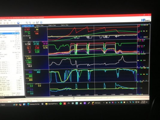
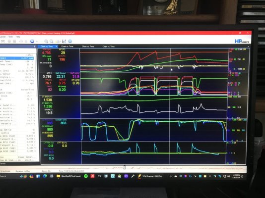
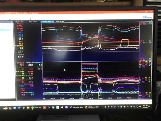
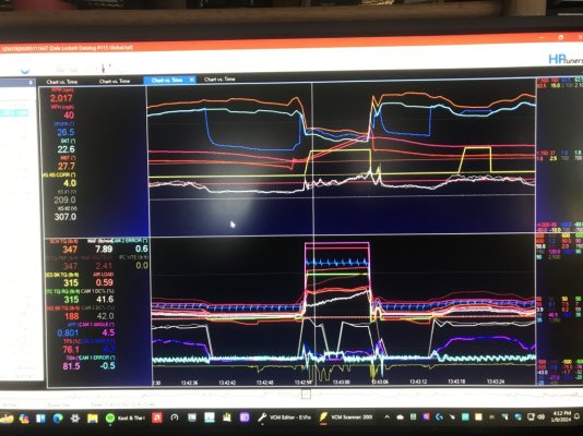
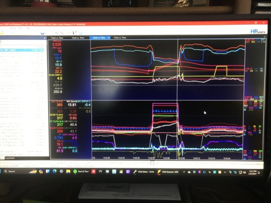
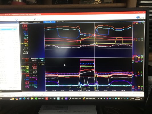
Here are some pictures of my latest datalog recorded today showing this SO ECU applying accel lead-in spark advance timing then reverting back to the established base BKT\MBT Spark Advance timing curve spacing during a mini 4th gear rolling WOT hit that lasted for approx 10 secs.........did this to record my tuning to see if all is operating as I had ran all thru my calculator (I use a calculator to simulate the ECU running thru all the map timing settings......interpolation included........to make a recorded diagram of operational criteria to then use to check actual operations against for accuracy & repeatability......all passed on this latest tune revision\datalog thus this is the finished product that will serve all of my intentions for setting it up going forward).

All this operates normally until the APP is applied in a more aggressive motion (thus the term "transient load") that causes a SD predictive load calc to exceed .30 load (which activates the KS's for cyl knock detection while ECU starts applying extra KS-controlled spark advance timing along w\ the Transient Load Correction timing) while the operating engine RPM's are between 500-3,000. During normal operations the engine operational steady state airload runs between .16 load to .25 load (so no KS's are activated.......engine running off base BKT Spark Advance\BKT Spark Advance Correction timing only) up to speeds close to reaching 80 MPH-100 MPH on level\declining roads under the way I have her set up\tuned currently so I get to experience this in application fairly often depending on the amount of progressive throttle application......

You'll note that as of now, the BKT Corrections\Transient Load Correction map settings aren't affecting the KS applied max spark advance timing at all as it was shown to be doing on pg 2, post #36 so now the ECU is applying all of it up front w\o any hint of cyl knock at all........thus verifies what Ben Alameda has stated about using extra lead-in spark advance timing to boost engine off idle low RPM TQ response in his video.

You can definitely feel it when it comes on.......... Also, can see it working thru looking at the IM Readiness Mode 6 Self-Check Catalyst #1\#2 CE Ratio data........is now testing into the mid to high .1xx ranges since setting this up thus is working them MF #5461336 CARB-cert TWC OEM grade aftermarket cats a little harder but still is consistently within very stellar operational emissions ranges.

This is applying 26.5* of total initial spark advance timing to get going off initial WOT acceleration inputs from DBW APP\TB TPS signal ramp then backs down to a more normal 19.5* of spark advance timing past 3,000 RPM's (the Transient Load Correction timing interpolated\ramped in according to all map settings off KS's signaling no cyl knock exists then interpolated\pulled back out as engine RPM's come up to return all back to the normal operating setup).........this is the Ford-provided coding that already exists in all of the 05-10 MY SO ECU's OS programming\tune calibrations that Ford intended to be used for this specific purpose.........that most all just ignore\disable.......even Ford themselves in the earlier 05-07 MY OEM tune calibrations (all show 0's in all map cells which will ignore\disable the coding) & in all 08-10 MY tune calibrations (map was enabled but due to the way Ford setup all the spark advance timing tables to operate, this mapping was effectively blocked from being used.....so in another way Ford quietly "disabled" it).

This is why I had to rebuild both base BKT & base MBT spark advance timing map settings in the fashion that you see now in picture provided that will allow all of this to operate fully while at the same time keeping the operational base MBT Spark Advance\MBT Spark Advance Corrections timing curve in close enough proximity to base BKT Spark Advance\BKT Spark Advance Corrections\KS max spark advance combined timing curve while all of this is happening to prevent excessively high TQ calcs based off TM DD TQ Requests that could cause excessive IPC Wheel TQ Errors until all is returned to normal operating parameters.

Has already been added to my upcoming FRPP Hot Rod cam tune calibration.............

1 Datalog #115 4th Gear WOT Accel Spark Advance Lead-In Timing Added Start.JPG

2 Datalog #115 4th Gear WOT Accel Spark Advance Lead-In Timing Added at Max.JPG

3 Datalog #115 4th Gear WOT Accel Spark Advance Lead-In Timing Fully Backed Out.JPG

4 Datalog #115 4th Gear WOT Accel Spark Advance End.JPG

GlassTop09 Finished Optimized Spark Lead-In Accel Timing Maps Setup.JPG
 

Attachments

  • obdiimode6data1924.txt
    7.2 KB · Views: 2

GlassTop09

Senior Member
Joined
May 24, 2019
Posts
1,145
Reaction score
526
Location
Farmington, NM
I tried to post the 2 HPTuners Tuning School videos that I attempted to do some time back.............still a no go w\ those..........

Sorry.
 

GlassTop09

Senior Member
Joined
May 24, 2019
Posts
1,145
Reaction score
526
Location
Farmington, NM
FYI.......................

Here is another video from Ben Alameda Racing titled "Piston Position during Spark Ignition in Crank Degrees".........


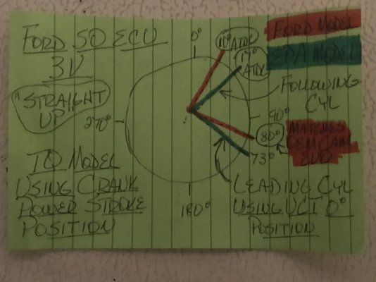
Now put what Ben says in this video from all he is demoing using a cam degree wheel & dial indicator to show piston position off crank degrees of rotation, is the optimum piston position crank degree angles for max TQ generation during a power stroke cycle from spark ignition ionization thru fuel burn crank angle timing off compression\ignition into perspective from my modeling of Ford using a 10* ATDC power stroke crank degree positioning along w\ Wallace Racing's Piston Position calculator using an engine's stroke length & con rod length according to the amount of crank degree rotation from TDC to achieve max TQ generation from fuel burn off compression\ignition by setting the cam's .006" lift adv dur cam EVO event timing to match up to the leading power stroke cyl's crank throw of 80* BBDC to position the following cyl crank throw coming into the same power stroke cycle at 170* BBDC (or 10* ATDC) to complete a seamless TQ handoff from the leading cyl to the following cyl during the same power stroke cycle.......

I just found\watched this particular video of Ben's this evening.......................

When I use Ben's given fuel burn rate in crank degrees of 25* & spark ionization to start the fuel burn rate in crank degrees of 6*, counting backwards from 10* ATDC this puts the initial theoretical spark event during compression stroke occurring at approx 21* BTDC..........my now current actual total WOT spark ignition timing event during compression stroke is occurring at 19.5* BTDC...........w\o any cyl knock found yet...............w\ my Lunati VooDoo cam's .006" lift adv dur cam EVO timing at VCT 0* of 88* BBDC retarded in the range of 8* to 12* cam timing retard (meaning matching up actual cam EVO timing event to crank throw timing between 80* BBDC to 76* BBDC........now where does this set up the following cyl's crank throw timing, thus piston position at.........?) w\ engine making the highest sustainable EBTQ output to date of 228 ft-lbs..............

I have since bumped this WOT total spark timing up another .25* but weather conditions have kept me from making a full WOT hit at the moment so we may be getting even closer to reaching this theoretical spark timing point to achieve max cyl pressure generation at the optimal 10* ATDC crank throw power stroke piston position for optimal TQ generation...............

I find this very, very interesting indeed..................also find all this being more than just coincidence or luck.

Again, looks like the Ford engineers knew something about this some 18+ yrs ago & gave out good data to use to fully optimize their FRPP Hot Rod cams across the board but some of it is\was getting ignored thus not utilized..............not me..................

YMMV..........FWIW..................

Cross Plane Crankshaft TQ Modeling Position at VCT 0 Degrees Straight Up.JPG
 
Last edited:

JC SSP

Senior Member
Joined
Nov 8, 2022
Posts
1,079
Reaction score
466
Location
FL
Many years ago when I was building and racing my cars, I used a degree wheel and dial indicator to confirm the cam specs (cam card) is accurate. I have yet to see a modern camshaft not match up with the specs listed. I have even installed cams advanced & retard 2-4 degrees usually done at the crank since some cams already come ground with an advance built in and all performed flawlessly. If I every do another cam swap I will check it with the degree wheel and dial indicator just to be sure but I have simply just aligning the timing marks more times than I can remember and all have perfectly worked for me 100% of the time.

Regarding piston to connecting rod ratio which is essential to volumetric efficiency… I have played with Chevy 383 strokers in the past. The same engines with the 5.7 rod produce less torque and had a narrow powerband compared to the same engine with 6.0 connecting rod and good power from idle all the way to redline.
 
Last edited:

GlassTop09

Senior Member
Joined
May 24, 2019
Posts
1,145
Reaction score
526
Location
Farmington, NM
Many years ago when I was building and racing my on car, I used a degree wheel and dial indicator to confirm the cam specs (cam card) is accurate. I have yet to see a modern camshaft not match up with the specs listed. I have even installed cams advanced & retard 2-4 degrees usually done at the crank since some cams already come ground with an advance built in and all performed flawlessly. If I every do another cam swap I will check it with the degree wheel and dial indicator just to be sure but I have simply just aligning the timing marks more times than I can remember and all have perfectly worked for me 100% of the time.

Regarding piston to connecting rod ratio which is essential to volumetric efficiency… I have played with Chevy 383 strokers in the past. The same engines with the 5.7 rod produce less torque and had a narrow powerband compared to the same engine with 6.0 connecting rod and good power from idle all the way to redline.
Well then JC SSP, I don't have to say anything as from an old proverb............"it takes real to discern real"...............meaning that you already know & understand exactly what all of this means when properly applied using the DEPS version of VCT that these 3V's are using........as it is simply applying old school cam-to-crank "degreeing" using modern electronics according to the basic laws of physics concerning force application to a simple lever.........the real power is ALWAYS located within the CRANKSHAFT stroke\con rod length vs the cyl bore size.....IOW's the engine's DISPLACEMENT. A camshaft is the TOOL used to line up the 4 main cam timing events....IVO, IVC, EVO, EVC........at the optimum crank throw timing events that will set the engine up to produce the most TQ twisting force that can be created thru the cyl bore size which dictates the piston's total surface area that the cyl pressure is exerted upon.....psi = pounds per sq in area = force.

The cyl pressure part most understand..........the TQ leveraging dynamics thru the crankshaft thus engine displacement is what is going over most folks heads........been conditioned to think this is all due to the cams being used........when it isn't. The cams have a function to serve in this......but aren't the generators of this TQ output.

With this 3V using VCT, it is not the tuner's job to optimize the engine's TQ output......it's the tuner's job to use VCT to set the cam EVO timing to match up to the crankshaft's optimum throw in degrees which is 80* BBDC which will always set the following cyl's crank throw at the optimum 10* ATDC position so that the cyl pressure can reach it's max pressure buildup from the spark timing used at this same point at the right time, every time, so that the max TQ twisting force can be exerted thru the crankshaft, trans, driveshaft, axle to wheels............regardless of the cam's adv dur cam timing profile being used. Then just simply phase the cam's EVO timing using VCT according to engine RPMs & load to remain within the 80* BBDC to 65* BBDC crank timing window to retain optimum crankshaft TQ twisting force application to the rest until redline. Then use the rest of the Ford-provided SO ECU's OS coding\tune calibration mapping that Ford created specifically to counter the effects from retarding the cam IVC timing when retarding the cam EVO timing to maintain the optimal cyl pressure generation (which most tuners either disable or leave in Ford's OEM layout which neuters this) and\or take advantage of other Ford-provided OS coding\tune calibration mapping that can further enhance off idle, low RPM TQ output that the Ford engineers already knew would be an asset but due to their corporate requirements for marketing\warranty purposes had to disable or "neuter" this coding........but ALL of it is fully operational within the OS programming......just "sidelined".

Up to a tuner to figure all this out then how to optimally apply it............that's where the legwork comes in..........and where most folks (not all) who are commercial don't\won't take the time to do the work to figure this stuff out, figure out all the optimal tune calibration mapping layouts to take advantage of HP\TQ output opportunities as this takes time & effort to do........the knowledge level is the leverage.......the more you have the easier & faster you'll get there w\ less miscues along the way, the less you have the more difficult & longer it'll take & the more miscues\mistakes will be made........thus why the term "good enough" is usually the go to level......doesn't mean the tuning is correct\optimal, just means it is good enough for the tuner's time they put into tuning to get by while keeping the customers in the dark by deflecting most of the time to the customer being at fault when tuning issues arise\noted due to the customer not being in the know thus can't effectively counter............

Yep, I was there in that position at 1 time like the rest of all customers.............but not anymore.

Since the Ford OEM camshafts cam EVO timing at VCT 0* is set @ 80* BBDC crankshaft timing point.......any other camshaft's cam EVO timing point.......regardless if it is set at VCT 0* earlier than this 80* BBDC crankshaft point.......is phased to match this same crankshaft's 80* BBDC throw timing point.....then, as long as the cyl pressure generated onto the piston top at the same 10* ATDC (or 170* BBDC) crankshaft timing point in the same power stroke cycle is the same, the engine WILL PRODUCE THE SAME AMOUNT OF GENERATED TQ TWISTING FORCE as the Ford OEM cams..........because this ISN'T about the CAMS........it's about optimizing the CRANKSHAFT THROW LENGTH\CON ROD LENGTH & PISTON TOP AREA during crankshaft rotation....IOW's optimizing the engine's current DISPLACEMENT when it comes to optimizing TQ output.......period.

The optimal crankshaft TQ degree window is not large....is a small window that must be maintained or TQ generation will suffer........

Basic Mechanical Engineering 101...........is also the reason why the Ford engineers provided the .006" lift adv dur seat-to-seat cam timing profiles of both the OEM Ford cams AND their FRPP Hot Rod cams..........if you don't know where the optimum displacement point for TQ output using VCT is, then how are you gonna know where to set the FRPP Hot Rod cams up in the VCT cam retard tables to output the same?

Outside of just throwing mud up against the wall until some of it sticks..........?

This why I chose to go w\ the science............once applied properly, all the optimum points will be easily known thus easily applied thru VCT w\o a lot of fuss while practically guaranteeing operational success as all the "guesswork" will be removed up front.........for these FRPP Hot Rod cams & any other non-OEM performance cams used.........if the cam manufacturers designed their grinds to optimize around the same crankshaft throw's 80* BBDC timing point..............as given them by the Ford specs around Ford's vers of DEPS VCT being used w\ these 3V's.

Is also the reason why I also said at the beginning of this thread, I'm not gonna argue w\ anyone on this BBS concerning any of this either...........I don't need to prove anything to anyone else but myself.........I already am VERY familiar w\ the sciences\mathematics behind all of this, just needed to figure out what Ford was actually doing\intending by giving the cam timing data as they did..........after that the rest is history..........as Nike has phrased......."Just do it."

I post the before\after data gained from my work & let it do all the talking for me.

The expected outcome w\ my engine performance operating under the current Lunati VooDoo #21270700 cams AND the upcoming FRPP Hot Rod cams is inevitable from here on out.............just up to me to initiate\execute.

The rest of the info\learning I'm getting from ole Ben Alameda @ Ben Alameda Racing thru his videos & from other sources is just affirmation of what I've already learned\figured out & some damn good dynamics\info I wasn't aware of to apply by me further making use of the Ford SO ECU's OS coding\tune calibration to apply it within the OS programming boundaries to further optimize my engine's overall performance while not causing code process contentions creating unwanted side effects that can cause unwanted potential engine operational issues.......what the masses call "thinking outside of the box".

"This is why we test".........as Richard Holdener always quotes..........

This is why you listen to these old long-time proven racers\engine builders when they're putting out their hard earned wisdom on these YouTube videos.............check out Ben's "About" button in the description in his videos.......this man is well-known as a winning racer & engine builder for decades in the California\West Coast racing circuits.......so he's got the chops & knows some stuff............kinda like you JC SSP..........also is a Veteran so I salute him & his family for their service as well.

You're just being quiet & reserved w\ yours.....................:beer:

Ford gave folks the recommended optimum WOT VCT cam retard timing points up front--all of it is based off the same crankshaft's 80* BBDC crank throw timing\10* ATDC power stroke TQ positioning--to use to optimize WOT TQ outputs, but they figured tuners would know the basic dynamics in order to use the rest (the .006" lift adv dur seat-to-seat cam event timing data) to optimize off idle, low RPM to mid-range TQ outputs from a position of TQ output w\ VCT usage as they saw fit...................

It is the CAM MANUF's job to make sure that the other 3 cam timing events...cam IVO, IVC & EVC.....are positioned\optimized on the camshafts along w\ the cam lobe shape profiles & lift\duration criteria to work in unison w\ the crankshaft's piston positions as set in rotation by the crankshaft's stroke & con rod lengths in crank degrees off the same 80* BBDC crank throw degrees point that set the crankshaft thus piston positions within the cyl bores at the crankshaft's optimum 10* ATDC TQ generational positioning to further optimize this engine's TQ twisting forces by optimizing the A\F cyl filling thru intake velocity created thru optimizing the OL period using the exhaust gas negative pressure wave generated by the exhaust gas exiting velocity while the exhaust valve is still open when the intake valve is initially opened along w\ the cyl head's low lift flow potential to optimize the OL.....the earlier the cam IVO event occurs, the more opportunity for intake air mass to get moving & sped up to increase air velocity.....the later the EVC event occurs within a specific time window during the end of the OL period before the positive exhaust pressure wave rebounds back to the exhaust valve causing EGR helps to optimize intake air velocity creation thus optimize total A\F cyl filling or "the supercharging effect" after the EVC event has occurred & the piston is travelling down the bore during the intake stroke as air also has mass\weight so once you get it moving you're also generating inertia within it which will not allow the moving airmass to instantly slow down\stop once it has started moving at speed. Then the cam IVC event timing will determine 2 things......1.) the point at which actual mechanical airmass compression begins during the compression stroke & 2.) the amount of residual initial airmass compression occurring against the intake valve head from generated airmass inertia AND the slow initial upward motion of the piston starting to reduce the total amount of open cyl area as it is beginning to move up from BDC just before the intake valve completely closes against its seat........thus again, the "supercharging effect" w\o any mechanical assist.

Air is also considered to be a "gas" thus has compressible properties of it's own that also must be taken into consideration when max cyl pressure from ignition is also applied..........why the optimum window around the 10* ATDC crank throw TQ window is small......a few degrees either direction outside of the 5* ATDC to 15* ATDC is not favorable for optimum TQ output........too short of the 5* ATDC window can cause potential structural issues from overpressure, past 15* ATDC can\will cause too much cyl bore area exposure from piston top being too far down bore from TDC thus will lose cyl pressure exponentially as the piston top is further moving down the cyl bore & is slowly gaining piston speed as the crank throw length is increasing from rotation & no amount of spark timing increase will "fix" this......only will cause the remaining A\F burn to get more unstable thus cause detonation more easily......trying to regain compressed cyl pressures from combustion while "chasing the piston top moving down the bore" is a losing proposition concerning optimal HP\TQ output.........but far too many tuners are setting all this up unknowingly using VCT.......especially if engine is still in NA configuration.

FI usage can cover up a lot of basic tuning mistakes concerning TQ output that can go unchecked if the knowledge isn't known.........usually causing other issues........such as excessive emissions output from excessively "dirty" A\F combustion or fried catalysts from having to oxidize too much excessive CO & HC caused from this type of excessively "dirty" A\F combustion that some think is necessary to do in order to attain the HP\TQ outputs they desire thus is "good enough"...............when it really isn't in a fair majority of cases from my POV........

If a NA configured 3V is using total spark advance timing in excess of 23*-25*, this is a red flag of this setup AND potentially the knock sensors being too far desensitized to allow this much timing to be used...........

I posted a couple of datalogged test results demoing this by showing the WOT total spark advance timing used (30* BTDC) w\o knock & WOT EBTQ output (202 ft-lbs) from my tune optimized using 17* ATDC\73* BBDC crank throw positioning then advanced all the VCT map cam retard timing 7* to match the 10* ATDC\80* BBDC crank throw positioning that Ford used w\o any other changes made in tune calibration except the WOT total spark advance timing that I had to cut back due to KS's detecting cyl knock during the WOT hits until I got it to stop showing up at 19* BTDC but the WOT EBTQ output had increased to 218 ft-lbs in the process.............

This is why Brian Tooley @ BTR Racing keeps on making the case to stop focusing on LSA, ICL, ECL, GI advance, OL, etc so much......he NEVER SAID these points aren't important to know & to consider (that some others on YouTube are falsely accusing him of).........& put more focus\emphasis on using the 4 cam timing events (IVO, IVC, EVO, EVC) that when set actually CREATE the cam's LSA, ICL, ECL, GI advance, OL, etc you see on a cam card to optimize engine TQ thus output performance.........this is especially true when VCT is being used.......starting w\ the crankshaft's max displacement TQ generating degree points for power output THEN MATCH UP the cam's EVO timing events point to it......then keep it there as much & as long as possible across the entire engine RPM operational window............

The problem w\ this is that most folks don't have the chops or inclination to learn application of the science behind all of this.........just want the results.

Tis why I decided to make a .pdf w\ pictures.............I tried to give plausible explanations of the science & application of it w\ some pictures for visuals but 1 would still have to make some effort to apply it all............which I know is not what most folks really want.

Tuning industry isn't much different from working in the petroleum industry........everybody wants to be on top, but few will put in the necessary time & do the actual honorable work needed to get there........the rest try to run the old boy games & don't mind\care who or whom they have to step on to gain someone else's "favor" to then reach their "agendas".

I've got 34+ yrs served in the oil & gas industry to back up what I've posted.......don't have any inclination\desire to put myself back thru any of it......not now.

Only the few who will have no issue to put out a little effort.................

Ok I'm done.................at least I got it off my chest now!
 
Last edited:

GlassTop09

Senior Member
Joined
May 24, 2019
Posts
1,145
Reaction score
526
Location
Farmington, NM
I posted a couple of datalogged test results demoing this by showing the WOT total spark advance timing used (30* BTDC) w\o knock & WOT EBTQ output (202 ft-lbs) from my tune optimized using 17* ATDC\73* BBDC crank throw positioning then advanced all the VCT map cam retard timing 7* to match the 10* ATDC\80* BBDC crank throw positioning that Ford used w\o any other changes made in tune calibration except the WOT total spark advance timing that I had to cut back due to KS's detecting cyl knock during the WOT hits until I got it to stop showing up at 19* BTDC but the WOT EBTQ output had increased to 218 ft-lbs in the process.............
FYI...........................

Disclaimer.........remember all this has to do w\ VCT usage...............fixed cam-in-block designs are set in full by the cam manuf's & usually have to pick their poison to either optimize off idle low RPM & part throttle HP\TQ w\ WOT HP\TQ dropoff or vise-versa. This is why it is essentially considered in general to be a bad move to lock out cam phasers on a VCT\VVT equipped engine...........so don't confuse the 2...............

Now back to the topic in discussion..................

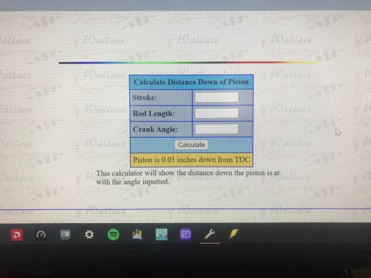
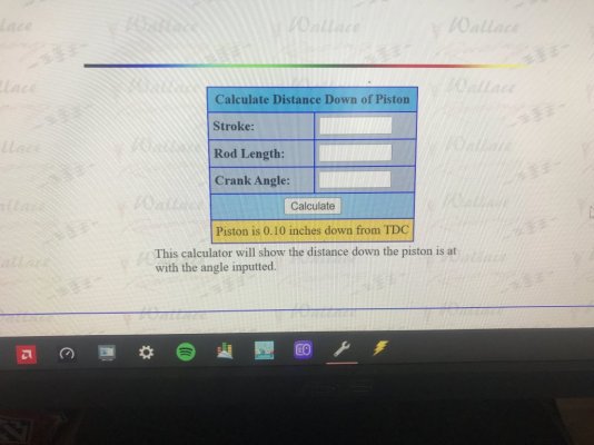
To put this in perspective, provided below are the Wallace Racing calculated piston positions from TDC I ran using this SBE 4.6L's OEM 3.54" stroke & 5.933" con rod length that corresponds to both 10* ATDC & 17* ATDC crank degrees that caused a 11* total WOT spark timing cut from 30* BTDC @ 17* ATDC to 19* BTDC @ 10* ATDC but picked up 16 ft-lbs of EBTQ output from 202 ft-lbs @ 17* ATDC (163* BBDC\73* BBDC)\30* BTDC\4,757 RPMs vs 218 ft-lbs @ 10* ATDC (170* BBDC\80* BBDC)\19* BTDC\4,756 RPMs...................

Amazing that .07" (or .693 cu in area) of extra piston volume created across only 7* of crank throw rotational difference can cost you 16 ft-lbs of TQ output & exposes the wasted futility\thinking of trying to use extra spark advance timing to gain\restore HP\TQ when the piston top is already positioned below the optimum TQ generation position window between .02" @ 8* ATDC (172* BBDC\82* BBDC) thru .05" @ 12* ATDC (168* BBDC\78* BBDC) to maximize the cyl pressure generation just as the piston is starting to move out of dwell & down the cyl bore from TDC w\ the crank throw lever length being long enough to actually begin to meaningfully transmit & multiply this force to the wheels before the leading power stroke cyl's cam EVO event timing is reached thus no interruption in TQ force application between the 2 cyls thru the crankshaft...........thus is chasing a piston moving down the cyl bore during a power stroke so is "over timing" the engine........utter futility.

Spark advance timing alone ain't the end all remedy for optimum HP\TQ generation..................but too many just keep on throwing spark advance timing at any & every situation..............

Only a 4* total crank throw TQ optimization window when a 3.55" dia cyl bore\3.54" crank stroke using a 5.933" con rodded engine displacement is used...........

Shows why these 4.6L 3V's can be so finicky to pull decent HP\TQ performance out of them...........they don't have enough displacement (thus a longer fuel burn time along w\ more A\F volume to create more usable cyl pressure force from increased cyl bore dia) to open up the optimum TQ positional window to make it easier to get within & if you're installing any type of performance camshafts in these engines you'd better be precise on your VCT cam retard timing setups or you're gonna pay a steep price on HP\TQ output.......especially during off idle, low RPM thru mid-range but also during WOT as well.

Why the science that was used to create all this is what is needed to fully optimize\tune out these small displacement engines........especially when staying NA.............also you just can't afford to reuse any of the OEM Ford-tuned VCT cam retard timing table settings.........you gotta essentially redo all of this in the SO OEM tune calibrations to get all what's there to get.

Much easier to do when you know exactly where the optimum TQ output crank degree position window numbers are..............

Wallace Racing Piston Travel Calc from 10 Degrees ATDC.JPG

Wallace Racing Piston Travel Calc from 17 Degrees ATDC.JPG
 
Last edited:

GriffX

Member
Joined
Sep 28, 2017
Posts
536
Reaction score
183
Thanks for this thread.
I got at least 20 different tunes and the driveability of most of them were horrible, now I understand better why. Since my tuner has a drivetest, logfile feedback loop, they are much better now. 99% of the time is not WOT and below 3000rpm and I think there is still room for improvement. After reading your thread, I doubt that a tuner can do this for you.
You have the Charge motion flap not removed?

(unfortunately HP Tuner doesn't work with all my cars, otherwise I would have probably bought it)
 

GlassTop09

Senior Member
Joined
May 24, 2019
Posts
1,145
Reaction score
526
Location
Farmington, NM
You have the Charge motion flap not removed?
Yes GriffX, they're removed thus aren't in the '08 MY OEM IM's intake runners (I'm using Steeda CMDP's)......been removed for quite some time (last time I had operational CMCV's on my engine was sometime in mid 2018 when I pulled my '09 GT's perfectly fully functional OEM IM & replaced it w\ the FRPP IM then loaded the BAMA tune to shut down the CMCV's..........before I found out that I didn't need the BAMA tune to do this w\ the SCT X4 tuner).

So, everything you've read in any of my postings have all been run w\ CMCV's removed.

Now I'm gonna type something here that some may take issue with concerning these CMCV's..........but after going thru all this legwork using the .006" lift adv dur cam timing profiles of the Ford OEM stock cams vs the FRPP Hot Rod cams, I believe I've also figured out why these were instituted w\ the OEM stock cams..........IMHO it ain't what I have seen quoted as being due to the cyl heads having poor intake port velocity flow capability as this IMHO is a red herring to misdirect from the real issue IMHO is the OEM cam's adv dur cam IVO timing once these cams are retarded thru VCT use away from VCT 0* during off idle, low RPM & mid-range operations (where most of the time the engine will be operating within) along w\ the short 34* OL timing period using adv dur cam EVC timing @ 19* ATDC @ VCT 0* (at VCT 0* & 19* ATDC EVC, the piston top will be around .12" from TDC......thus is already moving down the cyl bore during the intake stroke as the exhaust positive pressure wave from OEM exhaust manifold collector reversion has already rebounded & reached the exhaust valve just as it is closing onto its seat) is metering EGR into the CC's (this is intentional by Ford w\ this 3V engine.......is why no separate EGR valve & associated plumbing is needed........(EGR is used to counter NOx emissions created by high cyl pressure & heat from A\F combustion causing O2 molecules to artificially bond to the N2 molecules.....the number of O2 molecules attaching to a single N2 molecule is proportional to the cyl pressure & heat generated--meaning higher creates more NOx.....by cooling the CC area down to keep A\F combustion below the critical CC temp @ 2,500*F at which this molecule bonding will occur.......FYI for those so interested) thus needs to get evenly mixed into the incoming A\F mass to promote clean & complete A\F combustion.......but also at the same time, the normal IM intake runner air flow charge velocity (thru the cyl head's already exceptional low lift flow capacity thus also exceptional intake port velocity flowing capacity.....can't have 1 w\o the other in this 3V cyl head's design as you'd need both to take full advantage of any amount of intake-to-exhaust valve OL.....thus the red herring scenario concerning the poor cyl head's intake port velocity capability) that would've been created if the OEM cam's .006" lift adv dur cam IVO timing was still at 15* BTDC @ VCT 0*.......is reduced thru cam IVO timing retard from VCT cam EVO timing retard being applied (piston top will have essentially reached dwell--TDC--and have potentially started to move down the cyl bore during the intake stroke--earliest crank degrees ATDC for this to start is 4*) before the cam IVO event has occurred thus would lose sufficient time for OL to get intake airmass to start moving fast enough along w\ also losing net OL degrees due to EGR application from retarded adv dur cam EVC timing at the same time causing the incoming intake airmass flow velocity to start slowing down..............thus Ford needed a method to overcome this handicap......thus introducing the CMCV's........a mechanical method to restore any lost IM intake runner airmass flow charge velocity while the OEM cams are retarded thru VCT during off idle, low RPM & mid-range part throttle operations only. Once operational engine RPMs are above approx 4,100 RPMs and\or the OEM cams are advanced using VCT back to within 5*-8* min cam retard or lower towards VCT 0* timing to "correct" the OEM cam's adv dur cam IVO timing\adv dur cam EVC timing events to crank timing thus effective OL cam timing thus "correcting" the natural IM intake runner airmass velocities & shutting down EGR usage during high engine loads while also regaining the adv dur cam's IVC timing event to regain the dynamic compression lost (remember the OEM cam's adv dur cam EVO 80* BBDC timing event at VCT 0* is the same as the crankshaft's 80* BBDC crank throw timing that sets up the optimum 10* ATDC power stroke TQ generational positioning) thus at this point the CMCV's aren't needed at all thus are opened up fully.

So, in a sense, if anyone is still running the OEM cams in their 4.6L 3V's you probably should still be using these CMCV's...........unless you been tuned by a good tuner who understands all this & reworks the Ford setup VCT cam retard mapping to cut out all the excessive VCT cam timing retard around the off idle, low RPM & part throttle areas of this map w\ a little sprinkling into the same areas of the TM DD TQ Request mapping......the WOT part is pretty much good as it is.........go figure.

So also, if any performance cams are being used w\ this 3V engine, the cam manuf's have already designed their cam's adv dur cam timing profiles to eliminate all of this when their cam's are retarded thru VCT to match their cam's adv dur cam EVO timing to match the crankshaft's 80* BBDC throw timing thus w\ these the CMCV's are initially viewed as somewhat of a liability.....but IMHO "could" be used to "enhance" what IM runner airmass velocity is already created by the effective cam OL & early cam IVO timing......as long as the resulting net intake airmass flow velocities created w\ the CMCV's being used comes out to be a plus vs the CMCV's not used.

If you'll remember in my other Lunati VooDoo cam thread (pg 24, post #472), I posted about doing this very test since I still have the fully intact set of OEM CMCV's w\ actuator that came w\ the '08 MY OEM IM I bought to replace my FRPP IM to prove if these were a viable option to still incorporate from a performance standpoint w\ a tune calibration totally reconfigured away from any of the OEM Ford-tuned configurations.........in which I stated that from a science standpoint I can see these still providing some benefit.......but from a performance standpoint, especially if using non-OEM cams, are their use a practical consideration.........my hunch is no going by my current operational results running w\ CMDP's, but IMHO this also needs to be fully tested for final verification\disqualification since most of the non-OEM full VCT compliant cams are designed to be a "drop-in" fit.......which means dropping into an OEM equipped 4.6L 3V engine running an OEM Ford-tuned tune calibration & the basic engineering around CMCV use is actually sound.......their use may just enhance the natural "supercharging effects" from further increasing actual intake port airmass flow velocities thus actually increasing A\F cyl filling volume thus HP\TQ output.

I already had figured out how to use these in the tune calibration w\o needing to use the BKT\MBT Spark Advance Corrections\IMRC Open\Close mapping (or any other IMRC Open\Close mapping for that matter) at all so the testing results would be centered on the CMCV's themselves when ran closed vs open.................

Actual testing results could prove that these CMCV's are still viable to be used even w\ non-OEM cams running fully reworked non-Ford tuned tune calibrations during off idle low RPM part throttle engine operations..............thus been giving up some real available HP\TQ drivability all along.

But somebody needs to run the tests & gather the data.........................

Remember..............Ford also went away from using these CMCVs during the 1st Gen 11-14 MY Coyotes as well but went back to using them starting from '15 MY on...................

There may still be a there, there to all of this............

;)
 
Last edited:

GlassTop09

Senior Member
Joined
May 24, 2019
Posts
1,145
Reaction score
526
Location
Farmington, NM
I have since bumped this WOT total spark timing up another .25* but weather conditions have kept me from making a full WOT hit at the moment so we may be getting even closer to reaching this theoretical spark timing point to achieve max cyl pressure generation at the optimal 10* ATDC crank throw power stroke piston position for optimal TQ generation...............
FYI..........................

Well, I found out that my WOT testing section (section of road access to a major gas processing plant on the Res that I knew would get cleared sooner or later) @ NAPI International Raceway & Testing Facility is now back in service so I went out yesterday & datalogged her to see where all the latest tuning had gotten me to (in addition to the extra .25* of WOT spark advance timing mentioned above, I had also added some extra lead-in spark advance timing--.04*, .06*, .04*--as well in addition to what I had done thru the base BKT\MBT & BKT Load Increase Correction maps--between .40-.90 load, 1,000-2,250 RPMs thru using this section of the VCT Spark Advance Multi maps so both BKT & MBT sides will use it equally)...........

Found out that I had reached the limit off the 1st WOT run as the KS's replied no mas (fuel oct limited--IAT @ 36*F\ECT @ 199*F, ECT was up some 3*F so CHT\CC temps were hotter) & reported some cyl knock, so in next revision I just removed the extra .25* of WOT spark advance timing I had put in, left all else as set, flashed in & went out on 2nd run..............2nd WOT run I still got some cyl knock but the knock was approx 2\3 less than before but the WOT total spark advance timing was at 19* BTDC--where I was able to run w\o knock prior, so what's up?

After some time looking thru my datalogs the rest of the day for any clues.......it hit me that, by me introducing the extra lead-in spark advance timing at lower WOT RPM's to enhance initial TQ output, I'm adding in extra engine load in which the cooling system didn't have to deal with prior thus had increased the avg internal WOT cyl CHT\chamber temps that are now running close to the ragged edges of the E10 91 oct fuel AKI's limits.......so in this revision I pulled back out all that extra lead-in spark advance timing I had added thru the VCT Spark Advance Multi maps (reverted these back to my normal VCT Multi maps as shown in prior datalog pictures) so the only lead-in spark advance timing used now is the initial setup I made but while I was "in there" I went on & pulled another .25* of WOT total spark advance timing out for insurance, flashed in this morning & went out for 1st WOT run......................

It's funny how dialed in you can get to your car\engine from tuning it as long as I have been........because as soon as I started driving her after flash in\warmup & on the 1st instance when I accelerated her a little & I FELT how the engine responded on less initial lead-in timing.......I knew right then & there that this part was fully optimized as currently set & I had a good feeling that the upcoming WOT run was gonna be a good one.......20 mins later after getting to my spot & making the WOT hit clean w\o cyl knock across the full run @ 225 ft-lbs EBTQ @ same 3rd gear 4,757 RPMs, I also knew that as of this time, these Lunati's are fully optimized & optimally tuned out VCT-wise as I wasn't gonna waste any more time trying to chase 3 ft-lbs EBTQ.........so as of today she's a fully done deal w\ the Lunati VooDoo #21270700 cams!

This tuning level is what I call "good enough".

Long time coming but I learned\figured out a LOT of very useful stuff that'll come in very handy in any future tuning w\ this SO ECU.........;)

Now to throw in some hypotheticals.........using my last dyno run sheet of 352 HP, 320 TQ peak to peak & max 217 ft-lbs of WOT EBTQ I recorded on a WOT datalog of my prior tuner's tuning that was used w\ this dyno run, I came up w\ a multi for TQ of 1.47 & for HP of 1.62, so when now run against my now WOT EBTQ output of 225 ft-lbs this gives a hypothetical HP peak of 364 HP & TQ peak of 330 TQ (rounded all results down to the lower denomination) x std 15% driveline parasitic loss gives 418 HP\379 TQ FW peak to peak (not accounting for any perceived chassis wind drag coeff or road elevation incline.......I intentionally make\made all these WOT hits going up an inclining stretch of road surface on purpose to add additional load to engine outside of full chassis weight w\o any cool down from driving to get to this spot so no hero runs......guessing 5*-7* incline), based off the same dyno setup & in the same area but slightly higher elevation................naw, only hypotheticals.

The beauty of tuning out to specific optimal VCT cam retard timing to match up to the optimal 10* ATDC\80* BBDC crank TQ timing point profile is that, when the different cam timing profiles are laid out using VCT, the shape of the VCT cam retard timing curves will be very similar to each other, thus so will be all the other spark advance timing used........in fact, the only maps to really adjust to account for any spark advance timing differences will be the BKT\MBT Spark Advance Corrections VCT Multi Adder map spark timing settings.......all else will be essentially the same.

This is also the beauty of how\why Ford engineers laid out all the SO ECU's OS coding\tune calibration mapping in the way they did........once the base BKT\MBT Spark Advance timing maps are optimally set up the 1st time along w\ the rest of the tune calibration file settings, you don't have to mess w\ hardly any of this anymore when setting up a different set of camshafts as it'll all be within the VCT cam retard mapping & VCT Spark Advance Multi Adder mapping going forward.

Only a few pertinent settings here & there that'll need to be changed........like FI EOIT ref CA for starters........all stuff that can be done up front before the tune is even loaded up, then finish up w\ tuning the TM DD TQ Request mapping to tastes once cams are installed & running.

The only fueling changes you should need to make is during WOT OL\PE since the O2 sensors will be offline thus can't make up for any airmass changes due to different cam timing profiles\lobe designs being used.

It gets that easy going forward...............this is why I've spent all this time to get this all optimized up front on my Lunati's.

Quick & painless but highly optimized going forward...................:happythumbs:

Now I gotta pick up a 1\4" NPT needle valve & a new MC oil pressure switch (may as well change this out while removing it to install other stuff) to install on my new 1\4" NPT running tee fitting to tap into my engine's oiling system to record the actual cold start, hot idle & operational EOP's before upcoming refresh\upgrade work.

This is gonna be interesting..........................

GlassTop09 Final Lunati VooDoo #21270700 Cams VCT Cam Timing.JPG

GlassTop09 Proposed FRPP Hot Rod Cams VCT Cam Timing Map.JPG

Ford 09 OEM VCT Optimized Settings Based off 10 Degrees ATDC Crank Position.JPG
 
Last edited:

Dino Dino Bambino

I have a red car
Joined
Aug 11, 2014
Posts
3,910
Reaction score
1,777
Location
Cyprus
Time for another dyno run to find out.
My original prediction was 352rwhp & 335rwtq. Your HP was bang on last time but the TQ seemed low. I think you'll be much closer this time.
FWIW, the drivetrain loss on an 05-10 GT is ~12% at maximum TQ and ~13% at maximum HP. An aluminium driveshaft will drop those numbers by ~1%, and an aluminium flywheel will drop them by a further ~1%.
 
Last edited:

JC SSP

Senior Member
Joined
Nov 8, 2022
Posts
1,079
Reaction score
466
Location
FL
I have always calculated 15% for manual trans and 25% with automatic for parasitic loss.
 

Dino Dino Bambino

I have a red car
Joined
Aug 11, 2014
Posts
3,910
Reaction score
1,777
Location
Cyprus
I have always calculated 15% for manual trans and 25% with automatic for parasitic loss.

A drivetrain loss of 15% for a RWD manual and 20% for a RWD automatic dates back about half a century when transmissions were less efficient and torque converters were like boat anchors. Nowadays the figures for cars built in the last ~10 years are more like 8-12% for a RWD manual and 13-17% for a RWD automatic. The drivetrain loss is even lower on front-engine FWD cars and mid/rear-engine RWD cars since they don't have a conventional driveshaft. Bigger heavier wheels & tires will increase the drivetrain loss while a lighter driveshaft or flywheel will reduce it.
Dyno guys will often be overgenerous in fudging the crank HP numbers when attempting to convert RWHP to crank HP by using the "15% rule of thumb" for a manual i.e. divide RWHP by 0.85. I've even seen dyno guys use the "15% rule of thumb" incorrectly by multiplying RWHP by 1.15, which actually works out at a 13% drivetrain loss if you use that method e.g. 87rwhp x 1.15 = 100 crank HP.
 
Last edited:

JC SSP

Senior Member
Joined
Nov 8, 2022
Posts
1,079
Reaction score
466
Location
FL
Ok I understand the RWD, AWD, FWD parasitic loss concept….

Didn’t know the % went down for new drivetrain but I guess they have gotten more efficient. I would love to see the stock RWD HP/TQ for a new mustang with 6spd vs 10-speed auto.
 

Support us!

Support Us - Become A Supporting Member Today!

Click Here For Details

Sponsor Links

Banner image
Back
Top