FRPP Hot Rod Cams

GlassTop09

Senior Member
Joined
May 24, 2019
Posts
1,145
Reaction score
526
Location
Farmington, NM
Hi All,

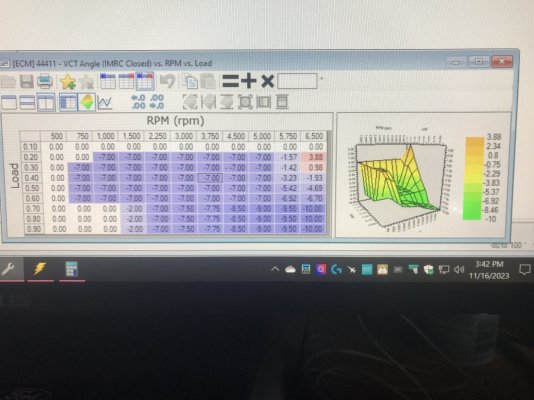
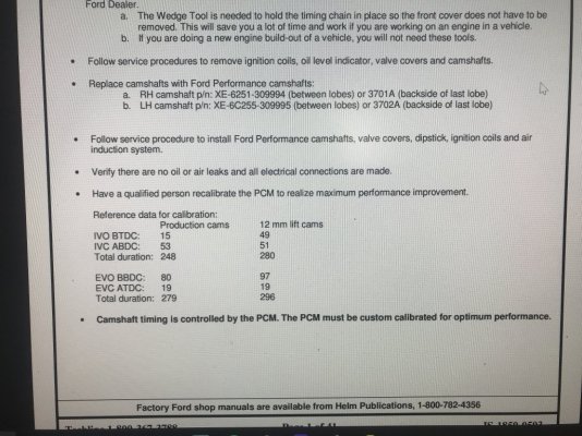
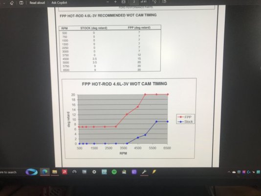
Just recently acquired a set of NIB FRPP Hot Rod cams for a song & have also acquired a set of FRPP Cam Phaser bolts so at some point in the near future I'll be swapping out & installing these cams in my 4.6L 3V V8 to get me some of that idle chop sound action but also to see just how much low end, mid-range & top end WOT HP\TQ--along w\ how much available HP\TQ across the board from off idle to redline--I can squeeze out of them using all the cam-to-crank correlation science I've laid out that I've used to tune my Lunati VooDoo #21270700 cams. Ford SVT engineers have given a lot of info thru the Hot Rod cam installation instructions sheet to use to optimize them using VCT & TM..........most are familiar w\ the recommended WOT VCT cam timing settings Ford provided......but how many also made note of the actual .006" adv dur cam timing point data Ford gave of these cams in comparison to the same .006" adv dur cam timing points data Ford gave of the OEM stock cams along w\ the extra valve lift height data & ran modeling of all this to get an idea of how to set up these Hot Rod cams to get the most available HP\TQ under the curve across the board as well as WOT peak HP\TQ? I can't answer this for others, but I can give some answers for myself as I did all this using Wallace Racing's various engine calculators to get an idea of what I'm looking at to determine the best VCT EVO cam timing mapping to set up to achieve max TQ leveraging application on the engine's cross plane crankshaft along with the optimum cam IVC point\VCT spark multi advance to optimize the dynamic cyl pressure curves to fully optimize this engine's meager displacement for max net TQ output from off idle thru redline.

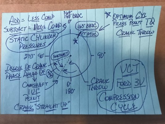
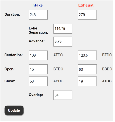
1st off, I found out that Ford used the 10* ATDC crank throw point to determine the TQ leveraging thru the crankshaft during the power stroke.....this matches up exactly w\ the OEM stock cams adv dur EVO timing point (80* BBDC) at VCT 0* cam timing (or "straight up" cam to crank timing) so the leading cyl in late power stroke position smoothly hands off TQ force application to the following cyl coming into early power stroke position--the 10* ATDC position--just as the leading cyl's EVO point is reached to start bleeding off cyl pressure thus entering the exhaust cycle so no spinning flywheel inertial momentum is needed thus all TQ force generated from cyls AND flywheel inertia is sent to drive the rear wheels. This is why the OEM stock cams can put out so much off idle, low RPM TQ output & is why Ford leaves these cams at VCT 0* cam timing until the engine RPM's exceed 1,000 RPMs. The Hot Rod cams same adv dur EVO timing point at VCT 0* cam timing is 97* BBDC or is opening a full 17* early thus the late power stroke leading cyl isn't taking full advantage of its full 90* crank throw length (losing TQ leverage force relative to the OEM stock cams at same VCT 0* timing point) as well as the early power stroke following cyl is still coming up to TDC during its compression stroke\ignition firing point thus also increasing pumping loss (counter force to actual power stroke cyl press pushing piston down thus causes some more net TQ loss) so engine spinning flywheel inertial momentum is needed to continue the crankshaft rotation to get the early power stroke following cyl into the optimum 10* ATDC position w\ max cyl pressure exertion on piston so now the early power stroke following cyl can start to exert its TQ force onto its crank throw to now start regaining twisting force to rear wheels AND to reload the spinning flywheel of its lost inertial momentum to be used on the next cyl exchange (which also will net some more TQ loss)......IF the OEM VCT cam timing mapping used to optimize the OEM stock cams is left intact as Ford initially set this up in tune calibration.

This is a fact that is killing FRPP Hot Rod cams (most other aftermarket cams as well for that matter......tested & found this to be true using my Lunati VooDoo cams) ability to make good low end TQ & so many tuners make the mistake of leaving this in-tune VCT cam timing mapping at stock settings......then wonder why these Hot Rod cams show to lose low end TQ output vs the OEM stock cams......even though at the same VCT 0* cam timing point, the Hot Rod cams actually DO have a dynamic compression advantage (earlier cam IVC timing point.....HR @ 51* ABDC vs OEM @ 53* ABDC) vs the OEM stock cams thus can put out more dynamic cyl pressure during compression stroke\ignition firing but due to this engine's small bore size, this dynamic cyl pressure advantage of the Hot Rod cams isn't near enough to begin to counter the massive TQ leveraging losses during the power stroke when these Hot Rod cams are left at the same VCT 0* cam timing point as the OEM stock cams. Another hard fact that is getting missed.......all this data is right in front of anyone who is looking at the cam timing data that Ford has put on the Hot Rod cam installation sheet......all 1 needs to do is to model it & all this comes out.

For the Hot Rod cams to have a fair shot at making good low end TQ output, the VCT cam timing needs to start retarding these cams ASAP off idle RPM's to get the cam EVO timing to line up to the crank throw at the 80* BBDC crank throw point......thus they need to be retarded at least 17* to bring the HR cam 97* EVO timing point to match up to the crank power stroke 80* BBDC timing point so the TQ leveraging is fully resolved by the time the engine RPMs leave 750 RPMs (idle) & reach 1,000 RPMs....the same 1,000 RPM point that the OEM cams are starting to be retarded from VCT 0* cam timing point for pumping loss gains\EGR flow for NOx reduction & any perceived MPG gains so now is negating the OEM stock cams TQ leveraging advantage. But now the HR cams have lost the dynamic compression advantage by retarding the cam adv dur IVC timing the same 17* vs the OEM stock cams still at VCT 0* cam timing.......this is why the Ford folks supplied the BKT\MBT Spark Advance VCT Multi Adder timing maps (that most tuners disable unfortunately by zeroing these maps out)......their sole existence is to supply a certain amount of additional spark advance correction timing as a multi to every degree of VCT EVO cam timing retard being used to counter the dynamic compression losses caused by VCT cam IVC retard to bring the dynamic compression back to VCT 0* cam timing scale to then allow the base BKT\base MBT spark advance timing to further apply spark timing to bring the operational cyl pressure back in line thus now the Hot Rod cams will have ALL the advantages swung to their favor as far as TQ output is concerned.....but then the HR cams have another advantage here that the OEM cams just can't compete with.....the induction advantage created by the HR cam's IVO thru EVC timing points....the OL along w\ the slightly higher valve lift creating better low lift head flow during the OL which, along w\ the early cam IVO timing point, will start the induction airmass flow moving much earlier using the better exhaust scavenging flow from the larger, longer OL to create higher induction air velocity entry into cyls which will cause a small "supercharging effect" thus packing more airmass into cyls also being aided by the later retarded cam IVC timing points so cyl have a much denser\cooler & optimally mixed\atomized A\F intake charge, better net dynamic compression gain thus higher cyl pressures at the 10* ATDC power stroke point AND now will get ALL the same TQ leveraging during the power stroke as the OEM stock cams did at VCT 0* cam timing, thus now the HR cams will "out TQ" the OEM cams from this point on out......IF the tuner will not use the stock VCT cam timing mapping as found but rearrange all this to the HR cams advantage (why I mapped the net cyl pressure of 2 cyls exerting their TQ force on crankshaft during same power stroke cycle to allow no more than 15* of crank rotation past the 10* ATDC point before opening the leading cyl cam EVO timing point to make max net TQ force......anything past this point is diminishing returns TQ wise but is losing exhaust gas velocity necessary to create good exhaust scavenging & is only good for reducing pumping losses for MPG purposes & for EGR purposes for NOx reduction.....but from my testing w\ my Lunati VooDoo cams, this extra cam EVO retard for EGR is not needed as there exists enough cam EVC retard at 32* max cam EVO retard (this is at the 15* max crank timing TQ point past the 10* ATDC timing point that uses 2 cyls TQ output during the same power stroke cycle) to sufficiently handle any NOx reduction thru EGR w\o negatively sacrificing net TQ output so there is no need to retard the cams any further than 32* max.

So all I'm doing is remapping the VCT cam retard mapping to correct the HR cams power stroke TQ leveraging to match\exceed the OEM stock cams from off idle low RPM TQ output on, use the BKT\MBT Spark Advance VCT Multi Adder Correction maps to regain the lost dynamic compression from retarded cam IVC timing thus now taking advantage of the HR cams better induction air charge cyl mixing\atomization & loading to then exceed the OEM stock cams TQ output even further & to maintain it from this point all the way to redline.

The only way to achieve this is to redo the Airload VCT load% cam retard timing map settings from the OEM stock setup so that all the new VCT cam retard settings favor the HR cams adv dur cam IVO, IVC, EVO, EVC, OL & fuel inj EOIT CA ref timings to make power from off idle to redline then follow up w\ the BKT\MBT Spark Advance VCT Multi Correction map settings to correct the retarded cam IVC timing to correct the dynamic compression back to the HR cams advantage to further make higher cyl pressures........then you should have a winning combination going.......sounds damn good chopping at idle but pulls like a freight train off idle onwards once VCT makes cam timing corrections to properly line up w\ the crankshaft's TQ leveraging capabilities.

If you now have any of the supporting components installed--such as a free-flowing induction charging system, LTH's & a FFE.......which I already have in place--to take further advantage of the induction cam timing by improving on the exhaust scavenging thus air intake charge loading, the FRPP Hot Rod cam HP\TQ output should only get better.

I've already witnessed this happening w\ my Lunati VooDoo cams on subsequent datalogs so only need to record this on a dyno sheet then do the Hot Rod cam swapout, redo the tune calibration to reflect all that I have typed here (BTW, the tune file is already done so waiting on cam swapout), optimize it using TM then record on dyno sheet. I'm figuring that the engine max WOT air load should exceed .80-.85 load (my Lunati's got to .77-.78 load max) from the Hot Rod's cam profile w\ slightly higher valve lift which should break 90% VE capacity @ 6,500 RPM redline by my estimation (my Lunati's got to 84% WOT VE around 6,184 RPMs in 4th gear before the bug shield blew off car hood & I backed out).

So, this should be attainable as currently configured w\o a lot of effort on my end.................

Only thing left to do is to do it & let the data speak for itself.

Posted for those so inclined...............
Ford OEM Production 4.6L Cams.PNG

FRPP HotRod Cams.PNG

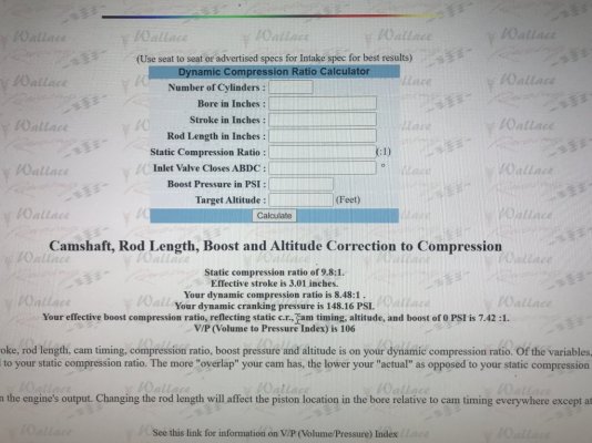
Wallace Racing Ford OEM 4.6L Cams Dynamic Compression Ratio Calcs.JPG

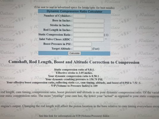
Wallace Racing Ford Racing Hot Rod Cams Dynamic Compression Ratio Calcs.JPG

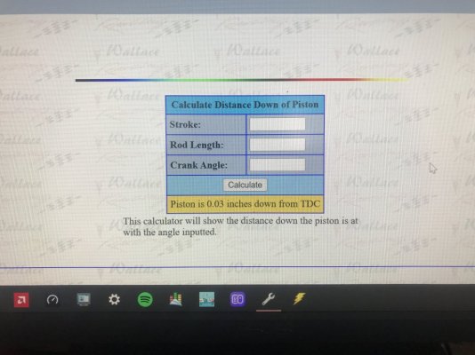
Wallace Racing Piston Travel Calc from 10 Degrees ATDC.JPG

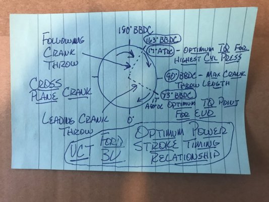
Ford 4.6L 3V VCT Optimum Power Stroke Timing Relationship.JPG

Ford 4.6L V8 Optimum Power Stroke Cyl Press Using 90 Degree Crank Lead Follow Cylinders.JPG

Ford 4.6L 3V VCT Intake Dynamic Compression Cycle.JPG
 

yote0

Member
Joined
Jun 11, 2023
Posts
66
Reaction score
21
Location
US
So you can set up and tune the FRPP Hot Rod cams and negate the inherent loss of low end torque? Would have been nice info to know back in the 00s. I will be watching for your results when the cams are actually swapped out.
 

Dino Dino Bambino

I have a red car
Joined
Aug 11, 2014
Posts
3,910
Reaction score
1,777
Location
Cyprus
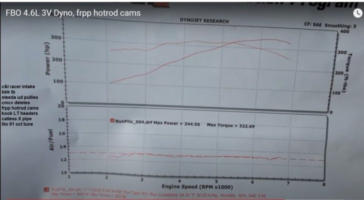
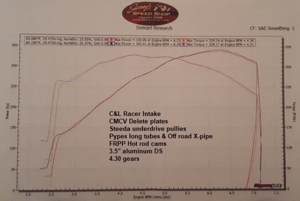
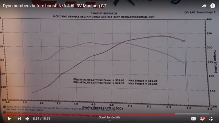
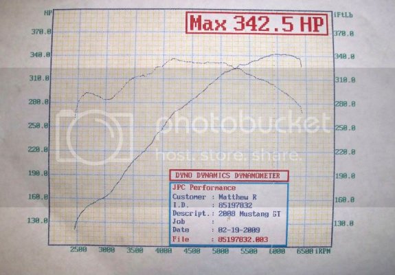
Here are four dyno graphs of 3Vs with essentially the same bolt ons (CAI, CMDPs, UDPs, LT headers) plus Hot Rod cams. All four are in the 340-345rwhp range and though the peak torque values vary quite a bit, the torque curve rises steeply from 3000-4200rpm and all would feel soft from idle to 3000rpm.

Hot Rod Cams 1.jpg

Hot Rod Cams 2.jpg

Hot Rod Cams 3.jpg

Hot Rod Cams 4.jpg
 

GlassTop09

Senior Member
Joined
May 24, 2019
Posts
1,145
Reaction score
526
Location
Farmington, NM
Here are four dyno graphs of 3Vs with essentially the same bolt ons (CAI, CMDPs, UDPs, LT headers) plus Hot Rod cams. All four are in the 340-345rwhp range and though the peak torque values vary quite a bit, the torque curve rises steeply from 3000-4200rpm and all would feel soft from idle to 3000rpm.

View attachment 91673

View attachment 91674

View attachment 91675

View attachment 91676
1 question to ask here.............do you have the actual tune calibrations to look at that represent each 1 of those WOT dyno sheet results in front of you?

If not, then you're only using 1\2 of the available data to determine what you're implying...........you may find that the VCT mapping is very similar between them all w\ only the amount of base BKT\MBT spark advance timing being the determination.......which will determine the overall "feel" of the engine using the same cam profile.......

I also have in my possession 2 tune calibrations from 2 different tuners using these same cams that I can show you every mistake that was made & can show you that they both used the OEM stock VCT cam timing mapping w\o any corrections made to actually fit the HR cams cam timng profile as given by Ford themselves........w\ 1 of them actually disabling TM in the tune..........another mistake made......but due to the OEM VCT cam timing mapping used (that was not set up to accent the HR cams timing profile but the OEM stock cams timing profile) they'll both "feel" similar to each other........meaning soft & under powered at low RPMs.

You're free to see this how you may want to see it..........but I now see all this from a different vantage point of view so not in the same light as you do.

:beer:
 

GlassTop09

Senior Member
Joined
May 24, 2019
Posts
1,145
Reaction score
526
Location
Farmington, NM
FYI.............

Now there is 1 item I will be testing to see which ATDC power stroke position is the better of the 2 for HP\TQ output.

The drawings I provided were done using the 17* ATDC optimum power stroke position for max cyl pressure generation......got this from my EPA Ford Mod Motor HPTuners training videos & is what I used to model my Lunati VooDoo cam's cam timing profile for TQ generation off of.
As I stated earlier, I found thru modeling that Ford used the 10* ATDC optimum power stroke position for max cyl pressure generation so I modeled my Hot Rod cams timing profile in VCT mapping off this due to these being ground to Ford engineer's specs for the sound & power output they desired for this product.

If you did the modeling (as I have done) of the 2 positions they will create some differences that can be a pro in 1 sense but can also be a con in another........

The 10* ATDC position will not be as forgiving on spark timing advancement thus will be tricky to tune well w\o causing excessive engine stress due to the crank throw length being relatively short w\ the piston movement being just over a 1\32" down from TDC, especially if engine is more knock tolerant......you can run out of power before knock occurs thus stressing the pistons, rod wrist pin bearings\journal bearings & crank journal bearings for essentially no gain (hitting max cyl pressure generation while piston is still in dwell during TDC instead of at the 10* ATDC position.....this is how heads get lifted from spark advance timing overshoot). This will make it harder to tune out to max on the street so will need to walk spark timing in in smaller increments......may be better done on a dyno but I'll give her my best thru using TM to determine where this point is.

Whereas the 17* ATDC position is much more forgiving since at this position the piston is at just shy of 1/8" down from TDC w\ the rod length being slightly longer due to the 7* of extra crank throw rotation at max cyl pressure generation......providing a TQ advantage vs the 10* ATDC position but at the same time also giving a larger buffer area for spark advancement w\o running up onto the piston during dwell & also, due to A\F being a compressible mass, provide some knock tolerance as well thus can use more spark advancement to gain more net cyl pressure w\o knock.

I very well may find out that these FRPP Hot Rod cams may be better utilized at the 17* ATDC position where I optimized my Lunati's off of instead of the 10* ATDC position that Ford chose to use.

As in the words of Richard Holdener......"this is why we test".
 
Last edited:

Dino Dino Bambino

I have a red car
Joined
Aug 11, 2014
Posts
3,910
Reaction score
1,777
Location
Cyprus
1 question to ask here.............do you have the actual tune calibrations to look at that represent each 1 of those WOT dyno sheet results in front of you?

If not, then you're only using 1\2 of the available data to determine what you're implying...........you may find that the VCT mapping is very similar between them all w\ only the amount of base BKT\MBT spark advance timing being the determination.......which will determine the overall "feel" of the engine using the same cam profile.......

I don't have the tuning calibrations for any of them so who knows if the VCT mapping was properly optimized? I'd say probably not so I'm interested to see how much more lower rpm torque you can eke out of the Hot Rod cams with the VCT mapping optimized to the max. I doubt that it'll match the stock cams simply because there's no getting away from the effects of the longer valve opening duration and valve overlap, but there's certainly scope to reduce the amount of lower rpm torque loss and improve drivability.
I'm also eager to see what your car does on the dyno now that you have the Lunati Voodoo cam tune optimized.
 
Last edited:

GlassTop09

Senior Member
Joined
May 24, 2019
Posts
1,145
Reaction score
526
Location
Farmington, NM
FYI.............

Now there is 1 item I will be testing to see which ATDC power stroke position is the better of the 2 for HP\TQ output.

The drawings I provided were done using the 17* ATDC optimum power stroke position for max cyl pressure generation......got this from my EPA Ford Mod Motor HPTuners training videos & is what I used to model my Lunati VooDoo cam's cam timing profile for TQ generation off of.
As I stated earlier, I found thru modeling that Ford used the 10* ATDC optimum power stroke position for max cyl pressure generation so I modeled my Hot Rod cams timing profile in VCT mapping off this due to these being ground to Ford engineer's specs for the sound & power output they desired for this product.

If you did the modeling (as I have done) of the 2 positions they will create some differences that can be a pro in 1 sense but can also be a con in another........

The 10* ATDC position will not be as forgiving on spark timing advancement thus will be tricky to tune well w\o causing excessive engine stress due to the crank throw length being relatively short w\ the piston movement being just over a 1\32" down from TDC, especially if engine is more knock tolerant......you can run out of power before knock occurs thus stressing the pistons, rod wrist pin bearings\journal bearings & crank journal bearings for essentially no gain (hitting max cyl pressure generation while piston is still in dwell during TDC instead of at the 10* ATDC position.....this is how heads get lifted from spark advance timing overshoot). This will make it harder to tune out to max on the street so will need to walk spark timing in in smaller increments......may be better done on a dyno but I'll give her my best thru using TM to determine where this point is.

Whereas the 17* ATDC position is much more forgiving since at this position the piston is at just shy of 1/8" down from TDC w\ the rod length being slightly longer due to the 7* of extra crank throw rotation at max cyl pressure generation......providing a TQ advantage vs the 10* ATDC position but at the same time also giving a larger buffer area for spark advancement w\o running up onto the piston during dwell & also, due to A\F being a compressible mass, provide some knock tolerance as well thus can use more spark advancement to gain more net cyl pressure w\o knock.

I very well may find out that these FRPP Hot Rod cams may be better utilized at the 17* ATDC position where I optimized my Lunati's off of instead of the 10* ATDC position that Ford chose to use.

As in the words of Richard Holdener......"this is why we test".
FYI......................

After fixing the idle creeping TB oscillations in my optimized Lunati VooDoo #21270700 cam timing set using 17* ATDC optimum power stroke position tune calibration, I got to thinking bout what I had typed here..........so I took it upon myself to fully test this out by going into the Airflow\VCT\VCT Configuration\VCT load% cam timing map & reset all EVO cam timing to reflect the 10* ATDC optimum power stroke position by cutting all set cam retard timing by 7* (the difference between the 2 "scales") so this will advance the cam's adv dur EVO timing 7* across the board on this map from where it was set previously. Now since I'm using the same settings everywhere else, this is a good test to run to see which 1 provides the better EBTQ output across the board (due to the way the BKT\MBT Spark Advance\VCT Spark Advance Multi Adder Correction works, this will reduce the additional spark advance timing used by the same 7* of cam timing advance.......which I found out doesn't change the total spark advance timing by much at all.......total spark timing dropped from 29.012* to 28.68* or .332*) & where the final optimized spark advance timing comes out based on what I had surmised doing this would\could cause in earlier posting. This will definitely raise the physical net dynamic compression by approx 7.35 psi avg per cyl (used my actual cranking static compression test results based off VCT 0* cam timing at Lunati's adv dur cam IVC @ 54* ABDC of 131.88 psi avg.....at 17* ATDC point this was 114.03 psi avg, at 10* ATDC this was 121.38 psi avg) but also still maintain the max power stroke TQ leveraging of 2 cyls during the same power stroke cycle using a cross plane crankshaft's 90* firing pattern......just advanced 7* earlier than prior thru VCT.......

Got revision all set up & flashed into ECU this morning & started the tuning process:

1st run--Saw from datalog that the EBTQ did indeed increase vs last datalog ran using 17* ATDC across the board.......but at WOT the knock sensors said no bueno & started knocking.......cut up to 10* spark timing in total but I noticed that when the spark cut dropped down to 24.7* the EBTQ output went up from 216 ft-lbs to 223 ft-lbs before the spark cut continued to bottom out at.....get this......18.0*........sound familiar......then started recovering from there. This indicated to me that at 28.68* total spark timing mark the 7* of VCT cam timing advance had moved the max cyl pressure point derived from it onto the piston during dwell--spark timing has overshot the 10* ATDC point so the fuel's AKI rating was exceeded thus knock occurred & ECU had to cut quite a bit of timing out to get the max cyl pressure down below the fuel AKI to stop the cyl knock. Engine wasn't hurt in any way due to me not being stupid & not giving the ECU all the room it needs to protect the engine (tuners who are too race-oriented will restrict the KS max spark retard map settings--usually to around 4* max retard--on the thought of restricting the amount of engine HP\TQ loss from any cyl knock event(s) to keep the engine "competitive" thus end up tuning themselves into a box that can be too small for proper & fast engine protection.........thus engine potentially destroys itself when pushed a little too hard) so I can get good data to work off of.

The next revision I cut the base BKT\MBT Spark Advance WOT timing (.70 load-.90 load rows) by 4* to line up w\ the data I saw when the spark timing cut went by 24.7* so total timing is now set @ 24.68* then blended the .50 load & .60 load rows into the .70 load row to gently\smoothly slope this spark timing transition cut from .40 load row into .70 load row then saved\flashed into ECU then tested again.

2nd run--This time we almost got there w\o knock @ 24.5*......cleared past 3rd gear WOT shift & got almost 1\2 way across 4th gear WOT before knock showed up....EBTQ output did drop a little but not very much (hung around the 215-217 ft-lbs area drawing a flat straight line across.....can see now that cyl knock was coming off B1 cam timing retard being a little slower than B2 cam timing off gear shift\TB swing cycle causing B1 cyls to have slightly higher cyl pressure until the B1 cam synchs up w\ B2 cam then cyl knock stops & starts recovering) w\ the amount of cyl knock being a LOT less....only 3.5* this round so the max cyl pressure point is getting real close to the 10* ATDC position.

This revision I cut the same base BKT\MBT Spark Advance WOT timing in the same manner as above by 2* this time thus setting the max total spark advance timing @ 22.5* then saved\flashed into ECU then tested again.

3rd run--BINGO! Got a clean WOT run thru all 4 gear shifts w\ EBTQ output actually rising to 217-218 ft-lbs flat as a tabletop across all 4 gear shifts so we have now hit at\just below the 10* ATDC optimum power stroke cam timing position w\ max cyl pressure buildup.........by cutting a total of 6.5* of total spark advance timing out in relation to advancing a total of approx 7* of VCT cam retard timing......this result is demoing a very close relationship & is seeming to closely follow the cranking dynamic cyl compression difference of 7.35 psi or 1.05 psi gain per 1* of spark timing cut. So, all is now good & this test is verifying what should also closely transpire scenario-wise when I install the FRPP Hot Rod cams which Ford ground-set & tuned to the same 10* ATDC power stroke position std as used w\ the OEM stock cams (based off leading cyl crankshaft power stroke throw position & OEM cam adv dur EVO timing of 80* BBDC to line up the following cyl entering the same power stroke cycle at crankshaft power stroke throw position of 170* BBDC or 10* ATDC point where the piston is just starting to move down cyl bore w\ max cyl pressure being applied at VCT 0* straight up timing point).

Now the next item is what really got my attention........when I measured the net EBTQ output off TM control from this last datalog using this 10* ATDC positioning @ 22.5* max spark advance timing---then compared to the last datalog's net EBTQ output off TM control I have when the 17* ATDC positioning was optimized @ 29.012* max spark advance timing........I found that the 10* ATDC positioning results had a net avg of 13-22 ft-lbs TQ INCREASE vs the 17* ATDC positioning results using the same camshafts cam timing profile........across the board to boot--not just during WOT--using LESS overall spark advance timing!

So, from these results we KNOW the engine's HP output also went up above what it was prior doing this test........just need a dyno to record this but the butt dyno can FEEL this much TQ increase........

Demoing the power of using\optimizing dynamic cyl pressure along w\ maximizing the TQ leveraging thru the crankshaft during the power stroke thru using VCT to line all this up & maintain the relationship once off idle thruout the rest of the RPM range.

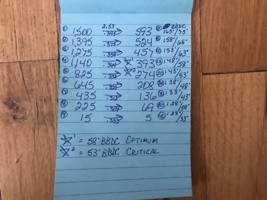
Also proves that you can retard these cams too far using VCT & can relatively lose available & peak HP\TQ output just the same as by not retarding them enough thru using VCT (why I made the calcs using a typical cyl pressure of 1,500 psi vs the leading\following cyl piston positions in their bores at 5* crank throw rotational position intervals past this critical 10*\17* ATDC to determine the net TQ output potential from 2 cyls providing force on the crankshaft throws at the same time during the same power stroke cycle to find the net optimal crank throw degrees to use this before the net cyl pressures of 2 cyls dropped below the cyl pressure of the following cyl during the same cycle)----58* BBDC for 17* ATDC\65* BBDC for 10* ATDC so for the 10* ATDC position (results show this 10* ATDC positioning to be the best 1 to use for total HP\TQ output.....vindicating the Ford engineers once again) the range of TQ leveraging optimization is between 80* BBDC to 65* BBDC crank throw to use to line up a camshaft's adv dur EVO timing point to fall between using the leading cyl in the power stroke cycle to line up w\ the following cyl in unison.

Posted for those so inclined & for informational purposes.........

Lunati VooDoo #21270700 Cams using 10 Degrees ATDC Power Stroke Position.JPG

Lunati VooDoo #21270700 Cams using 17 Degrees ATDC Power Stroke Position.JPG

Lunati VooDoo #21270700 Cams Retard Timing Differences Between 10 & 17 Degrees ATDC Positions.JPG
 
Last edited:

DieHarder

Senior Member
Joined
Nov 9, 2019
Posts
1,467
Reaction score
758
Okay Glasstop, I'll concede you're the next rocket scientist/tuner of the group. One of the reasons why I pay for a Lito tune vice try to do it myself even though I'd like to think I could but sadly, acknowledge I cannot. Hats off to members like you who actually can. Bravo Zulu!
 

GlassTop09

Senior Member
Joined
May 24, 2019
Posts
1,145
Reaction score
526
Location
Farmington, NM
FYI.................

Here provided below is the tuning info\data Ford provides online for sure (since I bought an open box set of NIB cams there wasn't any of these instructions provided w\ the cams) that I've had in my possession for the last 5-6 yrs as all of this is available on Ford Performance's web site & other various web sites as well.......so I've had a LOT of time to look at, work over & figure out what Ford's intentions were by providing all this......to help a tuner to fully optimize these Hot Rod cams cam timing profile.......both available HP\TQ (it is this area of a BKT\MBT spark timing map's .10-.60 load rows\VCT cam\spark timing map's .10-.60 load rows where the majority of folks are actually judging a cam's available low end HP\TQ output from.......not WOT, unless you're into drag racing.....) as well as WOT HP\TQ (the .70-1.0 load rows of both the BKT\MBT Spark timing maps & VCT cam\spark timing maps----this is especially important to a drag racer\roll racer as they both are stabbing the APP to the floor upon start of race thus the WOT low RPM HP\TQ output is important for getting the vehicle to accelerate as fast as possible from a dig to lower 60' times for drag racers or lower the, say, 60-130 MPH times for a roll racer). These are the folks who benefit the most from looking at any dyno sheets HP\TQ curves as these rep WOT operations......not available HP\TQ operations.

Now I know a lot of y'all already know about these & all this..........but you also might want to reconsider what\how you're implying what a dyno sheet recording WOT HP\TQ curves relates to the engine's same available HP\TQ outputs.......because you're actually talking about 2 distinctly different areas of an engine's total HP\TQ output curve that is using totally different criteria as well as A\F ratios to do what they do so IMHO you shouldn't blend the 2 into 1 anymore as this is very misleading\misinforming to others who may not fully understand all this nowadays.

The available HP\TQ side of a computer controlled engine using TM & VCT cam timing control is actually the hardest side to tune properly\optimally than it is for WOT as this is where the tune calibration's complexity comes into full focus\effect & this side just can't be fully replicated on a dyno due to the dynamic nature of TM to adjust both spark\VCT cam timing on the fly per varying loads\needs based on\off a simple TQ ft-lb request vs WOT HP\TQ which is mostly static in nature, outside of KS activity, thus is more predictable due to the similarity\simplicity of the tuning\setup......but it CAN be done well using remote tuning thru a driving datalog......but this is also where Torque Management is critical in determining the actual available HP\TQ outcomes as well as "driving feel"--thus it just shouldn't be disabled or incorrectly "setup\modified" thus throwing the results off......the driving feel along w\ it.

This is what I mean by tuners trying to tune a 4.6L 3V w\ VCT like a 4.6L 2V\4V w\o VCT.....................

Long gone are the days of using fixed cam timing-to-crank timing relationships that made using a dyno sheet recorded engine WOT HP\TQ output relative to available engine HP\TQ output (what Richard Holdener is mostly testing within since the majority of the engines he's testing on are either originally fixed cam to crank timing in block designs or VCT\VVT engines w\ VCT\VVT locked out...thus is now converted to the same "fixed cam to crank timing in block design.....becoming misleading in real world comparison operations", but now I've seen in a recent video of his that even he is starting to come around as I saw that they\he actually started to use an OEM ECU instead of using the Holley standalone engine management systems they've commonly used to control a Ford Coyote AND\OR the GM GenV & up LS3\LT4 engines due to their use of VCT\VVT control along w\ TM........so we also should change\adapt to the world of computer-controlled TM operated engines using some variation of cam VCT\VVT control.......if we want to be relevant in what we're wanting\intending to imply to others.

Now if 1 may be so inclined to rather shoot at the messenger than actually consider the info provided itself.........just know I have a very thick skin & don't really mind someone disagreeing with what I typed here & I'm not gonna get into an argument over any of this either as I know that the results will do all the talking for me.......all I need to do is to get the understanding\knowledge & application of said correctly applied.

Just saying..........................

The Ford provided recommended WOT VCT cam timing profile is widely used by tuners of these Hot Rod cams to optimize WOT HP\TQ outputs thus will only vary due to other items\issues (or tuning miscues as well) that are common to occur during WOT operations.

But the other Ford provided OEM cams vs Hot Rod cams physical .006" adv dur cam IVO, IVC, EVO, EVC & valve lift data.......which is critical to setting up a VCT cam retard timing map\VCT BKT\MBT Spark Advance Multi Adder Correction timing maps to optimize the cam-to-crank timing relationships to get the optimal available HP\TQ outputs from these Hot Rod cams in relation to the OEM stock cams is what I've noted that most tuners of these cams (or any aftermarket cams for that matter) simply ignore & don't use\apply or make reference to in their tuning......only maintaining to reuse the OEM tune calibration's setup for spark timing\VCT cam timing that was intentionally set up to fit the OEM stock cam's cam timing profile w\o any corrections applied.......which even Ford themselves is implying on these instructions sheets that this must be redone to fully optimize these Hot Rod cam's cam timing profile to produce optimal available HP\TQ output using VCT thru TM......thus IMHO is why so many keep saying the same things about their low end available HP\TQ output capabilities......not due to the cams themselves......because they ALL KEEP DOING THE SAME THINGS THAT KEEP PROVIDING THE SAME RESULTS within the tune calibrations but EXPECTING DIFFERENT RESULTS.......so is it any real reasoning as to why the results keep repeating themselves?

Since Ford didn't provide a finished recommended optimal VCT cam-to-crank timing cheat sheet for setting these up for optimal available HP\TQ output as they did for optimal WOT HP\TQ output........most folks don't change any of this in the tune calibrations.......thus the repeatability of the results......all the tune calibrations I've looked thru from other tuners to date provided on the HPTuners web site Ford tuning forums show all this in spades as to date I've found not a single 1 that showed any changes in the .10-.60 load rows of either spark or VCT cam timing maps from the OEM settings that fit the OEM cam timing profiles.......but they also show some maps that are critical to getting this optimal available HP\TQ output AND some WOT HP\TQ output as well using these HR cams being disabled by some tuners thus hampering this even more........but you can't see any of this thru a dyno sheet.........only thru the tune calibrations themselves........but you can definitely FEEL THE RESULTS OF ALL THIS thru the engine's output after a HR cam install\tune that didn't rearrange any of this outside of the WOT side of tuning.......I've never heard anyone complaining about the Hot Rod cams WOT HP\TQ output, have you?

Only the low-end available HP\TQ outputs........................something to think about here, if you're so inclined. Maybe why no commercial tuners usually share any of their tune calibrations data w\ their customers...........but will give you the same line of they will not give any good low end TQ output due to their large OL.......?

This is why I'm gonna install a set of these & tune them myself........using ALL the stuff I've learned\known\worked out thru tuning my Lunati's that will directly apply to these Hot Rod cams along w\ the Ford provided cam timing data as well to then see what these cams will really do for myself.

I live by this saying........."Study to show thyself approved............."

I already know & like how they'll sound.............that's not my goal.

Posted for those so inclined...............
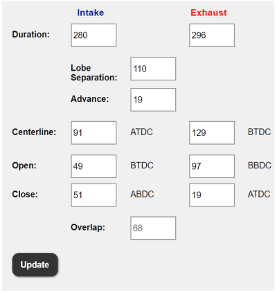
Ford Performance Hot Rod Cams Cam Timing Point Calibration Data.JPG

Ford Performance Hot Rod Cams Recommended WOT Cam Timing Tuning.JPG
 

GriffX

Member
Joined
Sep 28, 2017
Posts
536
Reaction score
183
Thank you! I had several tune iterations with Bama about low load driving issues (FRCAI + CMDP). WOT was ok, but not possible to leave the parking lot without bogging. They now have a datalog request with increasing load conditions. Increase revs step-by-step and hold for 10 seconds. The tunes are much better to use in real life now.

"all the tune calibrations I've looked thru from other tuners to date provided on the HPTuners web site Ford tuning forums show all this in spades as to date I've found not a single 1 that showed any changes in the .10-.60 load rows of either spark or VCT cam timing maps from the OEM settings that fit the OEM cam timing profiles......"

I did similar with tuning files for my 4cyl supercharged car, same result, only the last lines in the fueling map were changed (4psi -> 12psi boost change).

So, for the FRHR cam does this mean it is possible to have good city driving and gain on high rev combined?
 

GlassTop09

Senior Member
Joined
May 24, 2019
Posts
1,145
Reaction score
526
Location
Farmington, NM
So, for the FRHR cam does this mean it is possible to have good city driving and gain on high rev combined?
This is precisely what I'm gonna attempt to prove by me buying a set of them & applying all what I have learned from modeling them vs the OEM cams using the calibration data that Ford provided in the Hot Rod instructions sheet, worked out in the tune calibration file\OS programming & general tuning proficiency learned thru using HPTuners tuning hardware\software gained thru Evans Performance Academy's 05-10 Ford Mod Motor HPTuners training videos & on my own intuition as well.
 

Dino Dino Bambino

I have a red car
Joined
Aug 11, 2014
Posts
3,910
Reaction score
1,777
Location
Cyprus
So, for the FRHR cam does this mean it is possible to have good city driving and gain on high rev combined?

With the tune optimized, yes. That said, with the 3V you only have the cam advance/retard to play with so there's only so much you can do, whereas the Coyote adds a higher level of sophistication by also allowing the lobe separation angle to be varied due to its twin independent variable cam timing (TiVCT). This is why the Coyote can rev to 7500rpm and still be civilised at low rpm (basically have your cake and eat it), whereas on the 3V you'll either have to compromise low rpm driveability & idle quality for it to rev that high, or accept a lower rpm limit (~6700rpm) in order to have good idle quality and low rpm driveability.

1 question to ask here.............do you have the actual tune calibrations to look at that represent each 1 of those WOT dyno sheet results in front of you?

I know that at least three of the four dyno sheets I posted earlier were from engines tuned by Lito.

This is precisely what I'm gonna attempt to prove by me buying a set of them & applying all what I have learned from modeling them vs the OEM cams using the calibration data that Ford provided in the Hot Rod instructions sheet, worked out in the tune calibration file\OS programming & general tuning proficiency learned thru using HPTuners tuning hardware\software gained thru Evans Performance Academy's 05-10 Ford Mod Motor HPTuners training videos & on my own intuition as well.

I take my hat off to you!
You might even outdo Lito and become the next "3V whisperer". :D
 

GlassTop09

Senior Member
Joined
May 24, 2019
Posts
1,145
Reaction score
526
Location
Farmington, NM
FYI........................
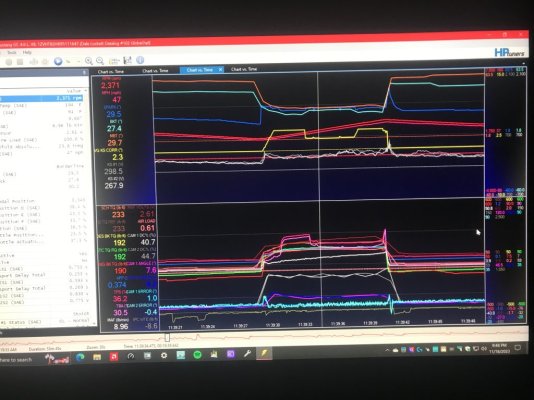
I have found another item in the tune calibration thru HPTuners that a lot of tuners say that this map doesn't work so just disable it............but I have concrete evidence that this teaching is incorrect & is costing folks some acceleration performance during CL operations, you know, the .10-.60 load available HP\TQ side of engine performance........regardless of the cams being used.

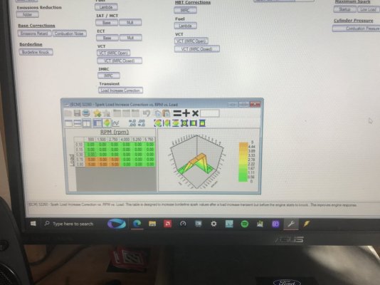
Under Spark\Advance\BKT Correction\Transient........the Load Increase Correction map that the Ford engineers provided is designed to help increase TQ output on any heavy acceleration inputs off idle that exceed .30 load (the enabling point for the KS to go active) by injecting a spark advance timing adder to the base BKT Spark Advance timing map settings to raise cyl pressure quickly during a transient (increasing engine RPMs & MPH) load increase (after the KS go active & show no cyl knock exists AND that there is available room between the base BKT spark timing & base MBT spark timing for the ECU to apply it).........up to 2,750 RPMs...........after which point this adder is then removed so all goes back to "normal operations". This shows to work during CL operations only where the APP\Throttle controls are in part throttle operations......may also work under WOT loads but I can't find a single instance of this getting applied by the ECU under WOT operations but this may be due to how fast the engine revs past the 2,750 RPMs max range during a 20 roll 1st gear WOT hit.......might actually work off a dig WOT hit w\ engine starting off at idle.......but I ain't gonna test it to find out as this is far more important to me working during CL part throttle operations......also don't want to risk breaking my 2-piece driveshaft........is why I use a 20 roll before making a WOT hit to datalog WOT operations.

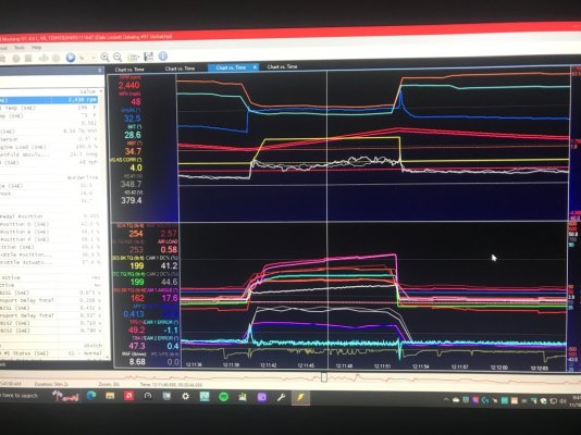
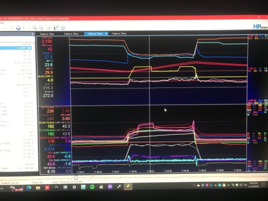
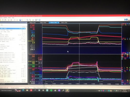
I have witnessed this occurring off & on during my tuning "career" but couldn't figure out what was causing the base BKT spark timing graph to close towards the base MBT spark advance timing graph when I was performing the DFCO 60-40 Misfire Monitor training procedure (the Mod Motor version of a crank relearn on the CKP sensor at front of engine) until I saw this start occurring in my latest datalog after running the 10* ATDC vs 17* ATDC power stroke crank throw positioning test when I compared the identical sections of both datalog's data using the 2 optimized ATDC power stroke positioning points. Under the 17* ATDC datalog, I had tried to use the KS to help w\ low RPM acceleration by enabling them earlier than the OEM .30 load setting (set this @ .25 load used by prior tuner) so the KS would apply the KS max spark advance timing of 4* to boost low RPM TQ output........but by the time I got around to running the test using the 10* ATDC power stroke positioning, I had given up on this & had reset this back to the OEM .30 load setting in the tune calibration.......this is when I saw this show up as shown in pictures below.

What you're witnessing is this Load Increase Correction map's settings being applied to the base BKT spark timing during the transient acceleration load phase of performing the DFCO 60-40 Misfire Monitor training to boost engine acceleration during low RPM operations.........that a lot of tuners have incorrectly stated that this map doesn't do anything so just delete it...............that is designed\intended by the Ford engineers to increase acceleration response TQ output during low RPM engine operations.......you know, the same area where a LOT of folks complain about low end TQ output response.............

There are 2 reasons why some tuners thought this didn't work.......1 of them is due to tuners leaving the OEM BKT\MBT spark advance timing setup in OEM configuration.......which in this thread: https://www.s197forum.com/threads/lunati-voodoo-21270700-camshafts.136257/page-24 post #477, I provided this reasoning along w\ the final rearrangement of all this in my tune calibration file that will eliminate any of the BKT Spark Adder Corrections from getting blocked out from the intentionally Ford set up version of this that is intended to do just this.

The other 1 is due to another quirk in the tune calibration\OS programming concerning the Spark\Retard\Enable\Min Load setting.......if this setting is set anywhere else besides the OEM .30 load setting, this action tends to disable the application of this Load Increase Correction map's settings.......but left at the OEM .30 load setting for KS enabling, this setting will be applied IF the base BKT spark advance timing used is LOWER than the base MBT spark advance timing & has enough room for this to get applied or the ECU will NOT ALLOW ANY BKT SPARK TIMING ADDER CORRECTIONS TO BE APPLIED if said corrections will cause the base MBT spark advance timing to be the LOWER of the 2!

As you can see........the Load Increase Correction map called for a total of 3.12* of additional spark advance timing to be applied (the rest was from the BKT Corrections\IAT & ECT adding another .52* of spark advance due to low IAT\ECT temps), but there was only a little over 2* of spacing between the BKT & MBT timing graph lines so ECU applied all of it but then subtracted the necessary spark timing from the 4* of KS spark advance timing (thus is NOT cyl knock) to keep the BKT spark timing just below the MBT spark timing.......this is by design in ECU OS programming as ECU will NOT ALLOW the BKT spark timing (what the ECU uses to operate the engine) to EXCEED the MBT spark timing (what the ECU uses for TM TQ calcs to determine the amount of TQ to use based on the TM DD TQ Request map's TQ output as chosen by the APP's applied A\D counts off driver input according to engine RPM's).

This is intended to offset the load lag......regardless of camshafts being used.......during off idle, low RPMs accelerations that will trigger KS activation for engine protection if this application does cause actual cyl knock while being applied.......until the engine RPM's exceed the 2,750 RPM max range.......then this adder is removed so all goes back to "normal operations".

Sooooo.............once again...............looks like the Ford engineers had thought of this AND had provided a remedy already.

Wonder just how many of y'all's SO ECU's are actually USING this?

My read is very, very, very few..............................both OEM & tuned calibrations...........

But I definitely KNOW of 1 SO ECU that is using this now! And BTW...........this map is adjustable as well..............
Think this might help out a set of FRPP Hot Rod cams to up low-end RPM TQ output.......................?

Sure is helping my Lunati's out..............the pictures are proving this. The KS output says that there is more to use if I desired to do so............

Amazing what Torque Management can do if it is given all the tools in the toolbox to use.................

Posted for informational purposes...............

Ford OEM BKT Spark Advance Transient Load Spark Adder Map.JPG

Ford DFCO 60 40 Misfire Monitor Training TQ Management 17 Degrees ATDC.JPG

Ford DFCO 60 40 Misfire Monitor Training TQ Management 10 Degrees ATDC Acceleration Transient ...JPG

Ford DFCO 60 40 Misfire Monitor Training TQ Management 10 Degrees ATDC Acceleration Transient ...JPG

Ford 10 Degrees ATDC Acceleration Transient Load TQ Management Max TQ Output.JPG
 
Last edited:

JC SSP

Senior Member
Joined
Nov 8, 2022
Posts
1,079
Reaction score
466
Location
FL
I have said once and I will say it again…. You should be in the tuning business. At least a cheat sheet or canned tune guide to help all of us make are cars run better.

This needs to be a mandatory sticky!
 

GlassTop09

Senior Member
Joined
May 24, 2019
Posts
1,145
Reaction score
526
Location
Farmington, NM
Okay Glasstop, I'll concede you're the next rocket scientist/tuner of the group. One of the reasons why I pay for a Lito tune vice try to do it myself even though I'd like to think I could but sadly, acknowledge I cannot. Hats off to members like you who actually can. Bravo Zulu!
Appreciate the kind words, DieHarder..............also in return I am thanking you for all the info you have posted concerning the topics of interest concerning improving our steeds as well........helped make mine a much more enjoyable ride to be in!

All I am doing is making use of my 28-34 yrs of petroleum industry experience in dealing w\ complex issues that require some mathematical understanding\skill to solve thus my knowledge\training levels derived from all of this.............the automotive industry is no different in scope & the enthusiast side is especially prone to the use of complex mathematical computations that, if known & used appropriately, can greatly shorten the tuning side exponentially & sharpen your skillsets.......if applied correctly & then properly tested to validate the results. Computer programming\technologies have always been a desire of mine since high school (during the Steve Jobs era) thus has been a side hobby for decades thus the knowledge gained from all this helps me to "see thru" the tune calibration settings into the underlying OS coding logic processing to then be able to see the mistakes others have made thru their settings choices in the tune calibrations.

The key is learning everything that the Ford engineers..........the folks who created the product, tested\verified every component\module used in\on the product & how all the various pieces intermesh w\ each other to then spit out what we "feel or experience". did, thought, intended, provided, designed along w\ the "why" to make the product operate in the manner that it was intended to be operated. In this type of industry, corporate decisions don't always jive w\ the creative engineering side thus the engineers are usually somewhat constrained in what they can\could do............doesn't make them stupid or ignorant in the slightest........as so many others are implying........whether intentionally or unknowingly.

Once you correctly\accurately learn all the ins\outs of all this, now 1 is able to fully exploit each & every piece of it to a desired result using most any aftermarket part that was also properly designed to operate within the ECU's OS programming code line logic & process mapping.......the heart of all modern computer-controlled vehicles.......to attain the performance\reliability\serviceability they can provide.

The rest is up to the individual to do the legwork to put it all together............so in the end.............

"You only get out of it what you actually put into it".

Now the tune calibration file(s) we all should want to get ahold of is the tune calibrations that Ford used in the same 07-09 MY FR500 class of factory racers as the Ford engineers weren't put on a leash w\ those vehicles........and they were very dominate during this period. It wouldn't surprise me if these very Hot Rod cams were the cams of choice in those 4.6L 3V V8-powered vehicles along w\ the FRPP 62mm TB.........I know for a fact that the CAI of choice was the 08-09 Ford Bullitt 83mm CAI design, the IM of choice was the OEM Ford production IM (don't know if they still had the CMCV's installed or removed) due to me actually seeing these pieces on 1....as well as the Tremec TR6060 6-speed trans that was used in the 07-09 GT500's running 4.10 gears in the rear axles w\ the 07-09 GT500 18" x 9.5" wheels until the other racers started complaining that these cars were too dominate so Ford was instructed to reduce the rear gear ratio to 3.73's.............didn't change the results any......just reduced the amount of dominance to make the others feel that they had a chance........back then.

:beer:
 

GlassTop09

Senior Member
Joined
May 24, 2019
Posts
1,145
Reaction score
526
Location
Farmington, NM
At least a cheat sheet or canned tune guide to help all of us make are cars run better.
Give me time, my man.............I actually have been figuring out how to do exactly what you've suggested............just know you may have\run into some beef w\ some tuners over this..................

Just saying....................

:):beer:
 

GlassTop09

Senior Member
Joined
May 24, 2019
Posts
1,145
Reaction score
526
Location
Farmington, NM
FYI.................................

Here's a couple of YouTube videos of an interview w\ 1 of the most prominent cam manufacturers in the performance business. A lot of folks doing tuning need to really listen to this guy...............you'll definitely gain some much needed knowledge that undercuts a lot of the going stated "talk" put out. Don't get caught up in the fact that he chose to specialize in GM products.........the majority of his knowledge spans across any ICE design.....

Enjoy!

PS edit--For some reason these 2 videos won't show up here but they are available on YouTube............................
 

GlassTop09

Senior Member
Joined
May 24, 2019
Posts
1,145
Reaction score
526
Location
Farmington, NM
Alright I should’ve given the reference info to the 2 YouTube videos when I saw that they wouldn’t load (had to finish packing to go OOT…..in Denver, CO for family Thanksgiving all this week) so sorry……

Look up 2 HPTuners Tuning School Skype interviews w/ Brian Tooley w/ BTR Racing about 4 yrs ago…….in these he explains technically how lopey cams provide the chopping sound…….you’ll learn that, even though OL does have influence on the chopping sound—the main cause for the chopping sound is due to grinding the cam’s EVO timing point to open very early during the power stroke to release the high cyl pressure into the exhaust…….like where the Hot Rod cams adv dur EVO timing point of 97* BBDC at VCT 0* cam timing……the same point where I demoed that is also causing the engine’s low end HP/TQ loss on the power side cam timing & I also pointed out that if the OL affected anything here, it would be thru affecting cyl filling/fuel atomization/swirl……which is directly affected thru exhaust gas velocity/scavenging during OL……..I can imagine the amount of exhaust reversion created from the high exhaust gas pressure back flowing back into intake due to the high velocity collector negative wave created off this amount of exhaust pressure release thru the HR cam’s 68* of high lift OL during the exhaust-to-intake transition cycle is gonna disturb airflow a little…….also causing even more TQ loss.

So the main influencer is early cam EVO timing during a power stroke cycle releasing high exhaust energy into the exhaust…….not induction side OL……

So, as soon as this cam EVO timing point is realigned to the crankshaft 80* BBDC, all this stops & reverses back to optimal TQ leveraging along w/ optimal intake aircharge fuel atomization/swirl/cyl fill velocity…..restoring max TQ output potential instantly…..only will need to apply a VCT spark multi adder to offset the amount of cam IVC retard to restore (or increase if desired) the cyl pressure loss to complete full recovery.

My intention was to have a very prominent cam manufacturer who specializes in making cams that provide good cam “chop” explain this instead of me saying it.

FYI…………..
 

Support us!

Support Us - Become A Supporting Member Today!

Click Here For Details

Sponsor Links

Banner image
Back
Top