Air Lift Install - Here we go slow but steady! - Continued #9
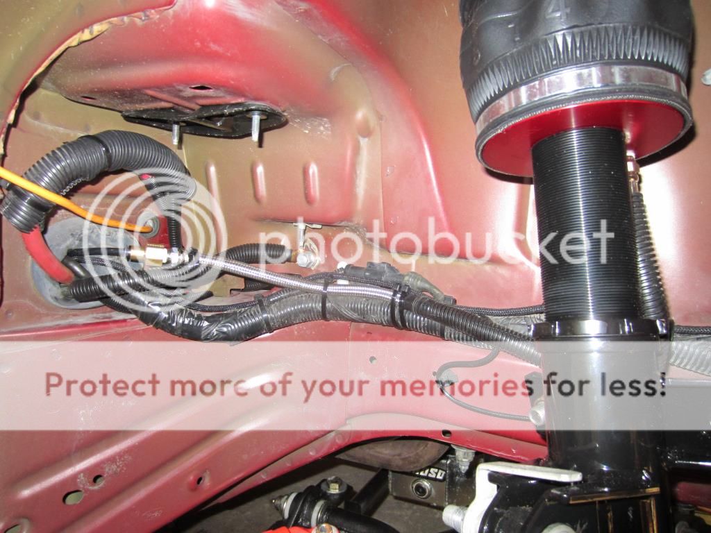
Attached the hard air lines to the leader lines on the front struts. Placed about a foot of ½” wire loom on the leader lines to ensure they would not rub directly on any suspension components. Not sure how others secured their leader lines, I was hoping to use one or two cushion clamps but considering the inner plastic panels and wire bundles there was not a lot of opportunity. I ended up cable tying the leader lines on both sides to wire bundles. Inner fender panels will not go back on until after testing for leaks and a road test.
Driver’s side.

Passenger’s side.
The DSpec shocks have a larger diameter shaft and require a larger than OEM nut on their isolator. Purchased a pair of OEM isolators from Ford, part number AR3Z-18197-A to fit the Air Lift shocks.

Here is a side by side comparison of an Air Lift to the Tokico DSpec.

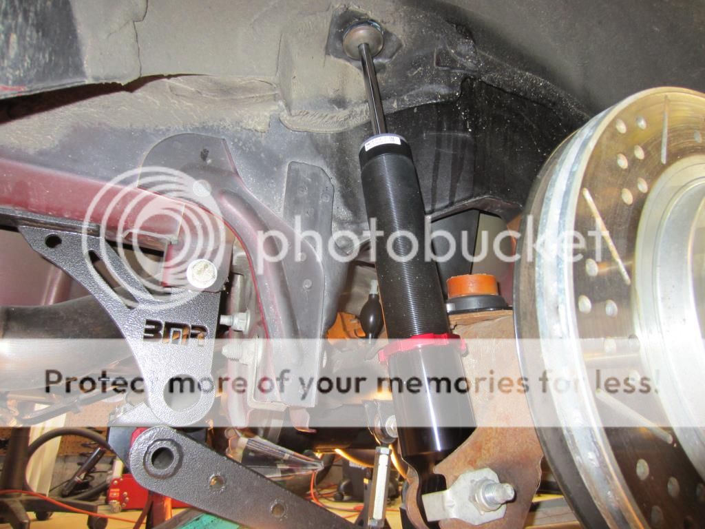
Installed the rear shocks.
Driver’s side.

Passenger’s side.
Terminated the strut and shock air lines into the manifold. They were cable tied together, ran into the tire well floor and then cut to length using the Air Lift tool. The air lines where inserted into the manifold following the Air Lift instructions:
- Manifold port FL or 1 to the front drivers side left strut
- Manifold port FR or 2 to the front passenger side right strut
- Manifold port RL or 3 to the rear drivers side left air bag
- Manifold port RR or 4 to the rear passenger side right air bag
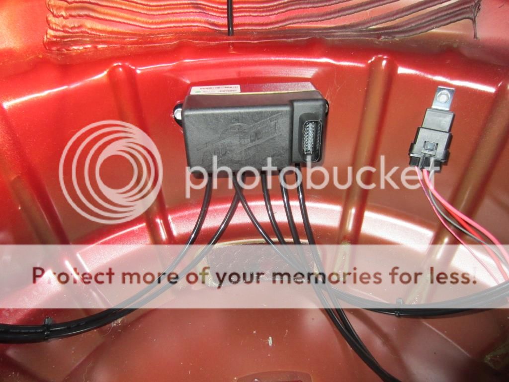
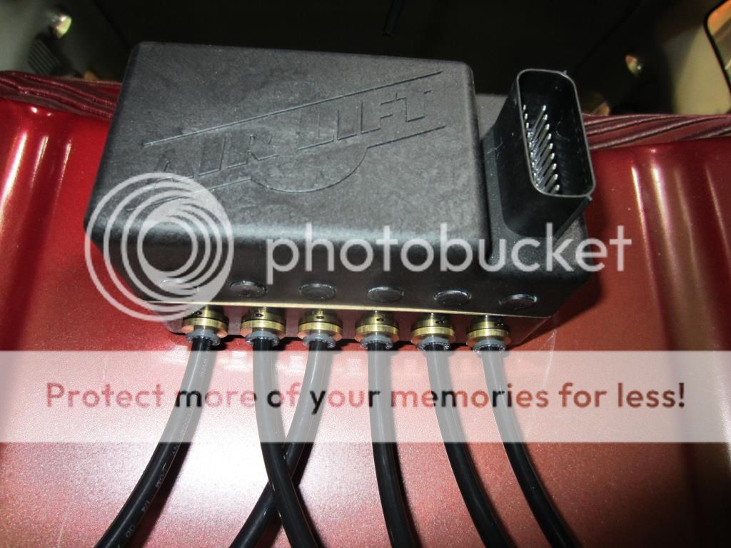
Added an air line to manifold port E or 6. Routed the exhaust air line to the rear of the tire well and cut a small hole in a rubber grommet underneath the driver’s side FPDM to pass the line through.

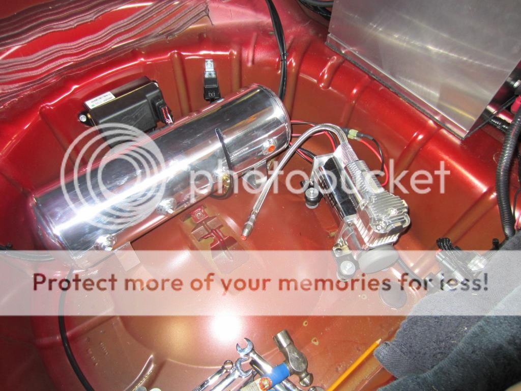
Drilled a hole in the tire well floor underneath the drain/fill port of the tank and installed a grommet. Now the tank sits reasonably flat on the bottom.

The 2.5 gallon aluminum air tank weights less than 5 pounds and I am going to fasten it down with 1/4-20 aluminum bolts and nuts.
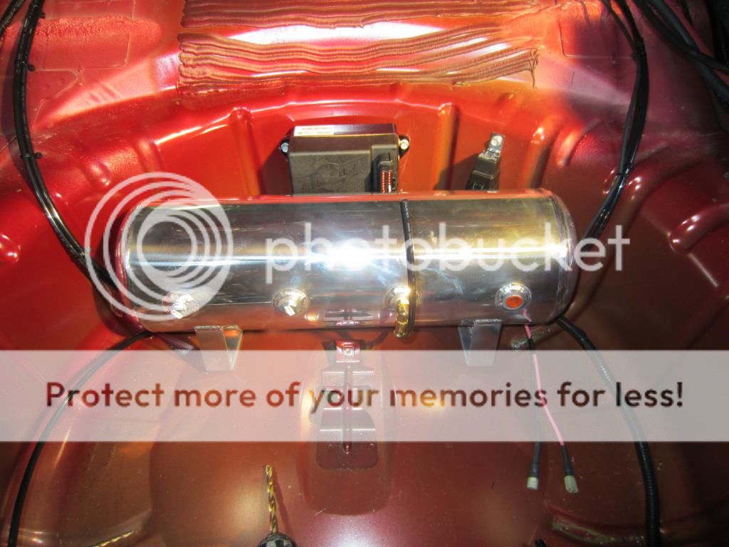
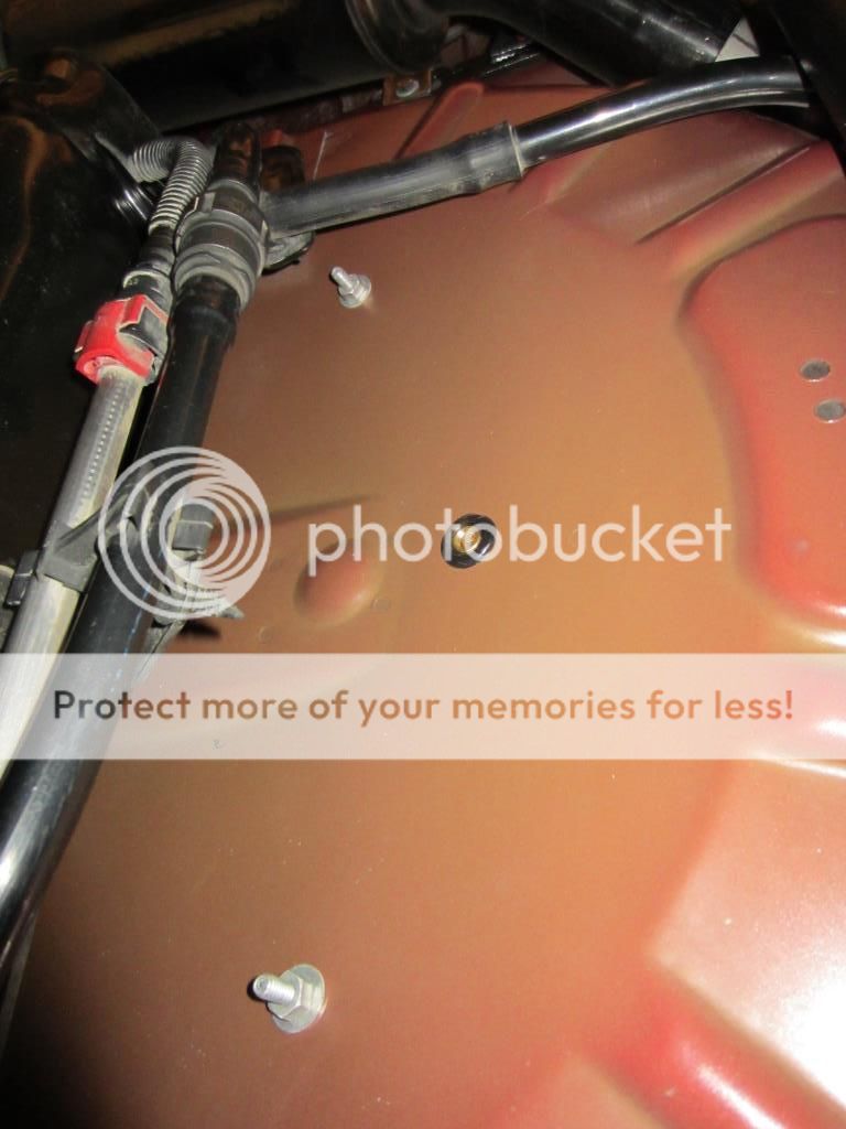
This shows underside of the tire well, the ¼ NPT straight air line fitting that the drain/fill line will be connected to and only two so far of the tank hold down bolts.
For inspiration I took this picture of the approximate mounting location of the VIAIR compressor.