There's no such thing as a ground loop; it's either a good ground or a bad ground. A good ground has low resistance and thus no noise.
For a good ground, run it to the same ground lug that the PCM uses.
No, but there's a ground offset when dealing with widebands, tuners, laptops, and OBDII connections for datalogging. I'm pretty sure that's what Texas was talking about. The ground offset needs to be accounted for if you want accurate readings.
This is from Innovates website
Click here for pictures
"Ground Offsets
A ground offset is a wiring problem that can change your air/fuel ratio readings, making them less accurate. This is a problem that should be tested for, minimized, and compensated for. What is a ground offset? Let’s say you have a positive wire that has 5 volts in it. That wire has to be grounded to complete the circuit. If you ground it to a really good ground (such as the engine block), it may not have any offsets. If the ground you chose is shared by other wires, perhaps with even more voltage in them, your 5v wire will have trouble passing through that ground. This can reduce the voltage in your wire, for example, from 1.6v down to 1.52v (a .08v ground offset). Not a big difference. But let’s plug that into our formula and see just how big it is. (1.52*3.008)+7.35 = 11.92. We should have 12.16, so our ground offset has changed the air/fuel ratio by .24. That’s almost a quarter point of inaccuracy, leading you to believe the motor is richer than it really is! This is why we need to test for ground offsets. Here’s how… Set up LM Programmer to put out 0v = 2.5, and 5v = 2.5. This will cause the LC-1 to send out 2.5 volts no matter what the air/fuel ratio is. You can use different voltages for this test if you want, but don’t use voltages near the end of the spectrum like 0v or 5v. When you’re done entering in the voltages, you have to hit the “Program” button to program the LC-1 or LM-1 to use these settings.
Now, data log the analog input in Live Link, but leave the formula set at just “V”. This will display just the voltage in the Analog 2 box.
While the reading will fluctuate ever so slightly, it should pretty much read 2.5 volts. If it does not, you’ve have ground offsets. The photo below shows that my Xcal 2 is reading 2.440 volts, even though I programmed it to send out 2.5 volts all the time. So my ground offset would be .06v. In my correction formula, I will have to add the missing .06v back in.
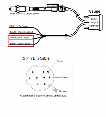
There will likely always be some ground offsets in a car, because the car’s OBDII port is grounded through the ECU. The ECU is grounded through the vehicles wiring harness, and eventually makes it’s way to the engine block. This long, commonly used path the ground has to take creates some ground offsets of it’s own. We can compensate for these offsets in our formula, but first let’s try to minimize them. The best way to minimize the offsets is by wiring the LC-1 correctly. First, the heater ground wire of the LC-1 is a fairly high current, so it should be grounded all by itself to the engine block. Next, the analog and system grounds should be connected together and grounded to a different spot. This new spot should not share use with any other grounds. And last, the Xcal 2 has an analog ground wire that is one of the three wires we’re using in the 9 pin mini-din cable. That ground wire should reference the same ground as the analog/system ground wires from the LC-1. So put them all to the same place. Now re-test for ground offsets and see where you are. Hopefully, you’ve gotten the offset down to around .02 volts or less. Whatever offset you have left, we need to compensate for it. Let’s say you put out 2.5v, but Live Link only shows 2.48v. Here’s what the correction formula should look like: ((V+.02)*3.008)+7.35. Remember, in a mathematical equation, whatever is inside the parenthesis happens first. So the V gets .02 added to it first, then it’s multiplied by 3.008, then 7.35 is added. So, our 2.48v example would have .02v added to it, bringing it back up to the 2.50v that it’s supposed to be. This ground offset should be tested for every once in a while, and any time you change the grounds on the car. For example, relocating the battery to the trunk, or fixing old corroded cables, etc. could change the offsets, and they should be re-tested.
The correction formula will always be ((V+GROUND_OFFSET)*RANGE)+LOW_END_OF_AFR.
There can actually be either negative or positive offsets, and you should add or subtract voltage accordingly. Most often, you’ll be adding missing voltage.
TIP: Once you come up with a compensated formula that is correct for your AFR range, write it down and keep it with your laptop so it’s there when you need it.
Tips and tricks
While some of this may sound a bit intimidating, it will become quite easy after you’ve done it a few times. There are a few things I want to mention again, to emphasize their significance. First off is correct wiring. Do it right the first time, and your life will be much easier. Keeping the analog and system grounds together with the Xcal’s Analog ground wire is important. And putting these three wires straight to the engine block as a ground is the best solution.
Second, testing for ground offsets is of major importance. If you skip this part, and end up with your engine air/fuel ratio being .2 or .3 off, it could be the difference between life and death on a nitrous or forced induction car. The bulk of these ground offsets will be cured simply by wiring the LC-1 correctly. What’s left of the offsets should be compensated for with the correction formula.
Third, understanding how the formula works will not only ensure that you are getting the right readings, but it will help you to better understand how the whole thing works. Take the time to read that section and work with the formulas until you fully understand it. You’ll be glad you did.
And last, I want to mention that I had to modify the 9 pin mini-din cable, where it plugged in to the Xcal 2. The rubber sheathing over the cable end would come into contact with the body of the Xcal 2 before the plug itself was fully inserted. This would cause the data link to come undone occasionally. The fix was to take a razor blade and carefully trim off about ¼” of sheathing. Different brands of cables will have different needs in this area. The cable mentioned above was not an SCT brand cable.
If you don’t like the looks of having a cable that is permanently attached to the LC-1, you can purchase a 9 pin female mini-din socket, wire it permanently to the LC-1, and install it in the car. Then, you don’t have to cut one end off of the SCT cable. You can simply plug the cable into the socket. This makes for a nice plug-and-play installation. The wires going from the back of the socket to the LC-1 should be made out of shielded cable like the 9 pin mini-din cable is. If shielded cable is not used, RF interference could skew the AFR readings."