Nice article on MBT, Rod ratio, etc.

Full_Tilt

forum member
Joined
Jan 20, 2011
Posts
1,697
Reaction score
1
Ive seen a few instances, on this forum and others, where people are unaware of or misunderstand some of these fundamental concepts. I have myself had trouble trying to explain them in simple words as well.
I stumbled upon this write-up early and found it to be well written and best of all its easy to understand. This is the kind of stuff that makes the difference between a good tuner and a bad tuner imo.

Its not Mustang specific, but it is Tech... so I suppose Chit-chat would be the place to put it. If not, please move it.


Introduction

This article is meant for the people who want to know more than “which parts do I buy to make more power”. This is meant for the people who want to know WHY those parts make power. Since the content is (and has to be) very theoretical, I won’t be recommending specific parts, comparing specific parts, or doing anything like that. I’ll try to keep everything simple and easy to understand, but I’ll assume that everybody reading this already has a fundamental understanding of engines and elementary physics. So for those of you who haven’t completely lost interest at this point, let’s begin.

Combustion Forces and Inertial Forces

The first part of understanding what makes torque is to realize that torque is not produced at a constant magnitude as the engine rotates. It comes in large spikes during the power stroke, and this behavior is further complicated by pumping losses, compression work, and the inertial forces created by the reciprocating components of the engine (namely the pistons). When your dyno reading says that your engine makes 115 ft-lb of torque at 5000 rpm, it’s actually saying that your engine makes an average of 115 ft-lb of torque at 5000 rpm. However, at any instant in time, the engine could be making 300 ft-lb or even -25 ft-lb of torque.

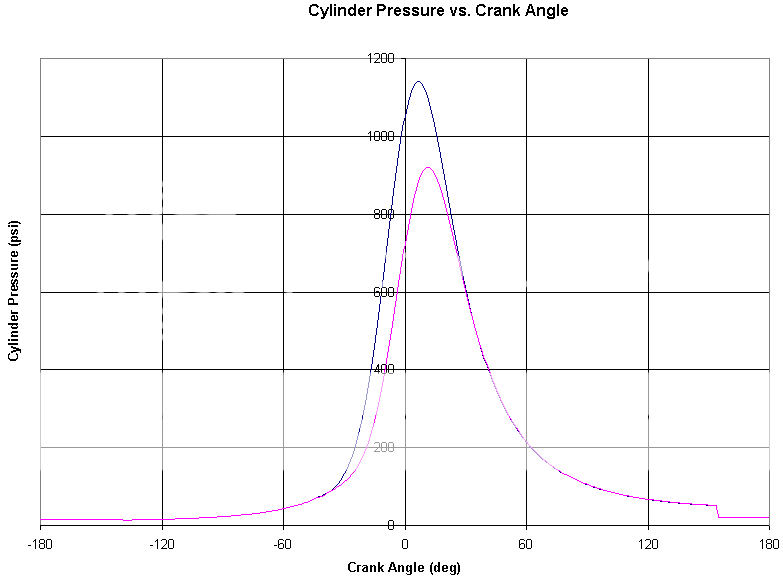
Let’s start with the main component that probably first comes to your mind: combustion. As fuel is burned, cylinder temperature increases rapidly. Since the pressure of a fluid in a fixed volume increases with temperature, the cylinder pressure also rapidly increases, and that pressure develops a force on the piston. The more fuel mass that’s burned per cycle, the more the cylinder temperature and pressure will rise. Most of that force is transferred through the connecting rod and to the crankpin. However, the angle between the connecting rod and the crank throw (the imaginary line that connects the center of the crankshaft with the center of the crankpin) changes as the engine rotates, and that has a large effect on how much torque can be developed. I’m sure most of you have used a wrench to loosen a bolt at some point. Is it easier to push perpendicularly to the wrench, or would you rather push on the end of the wrench, toward the bolt? In one case, all of your force is used to create torque to loosen the bolt, and in the other case, the only thing you might accomplish is shearing the head off the bolt. The same principle applies to the crankshaft. When the piston is at TDC, there might be a large amount of force in the connecting rod, but no torque is created about the crankshaft. When the connecting rod is at a 90 degree angle with the crank throw, the force in the connecting rod can most effectively be used to produce torque. This occurs anywhere from 60 to 80 deg ATDC, depending on rod ratio (I’ll talk more about this later). Additionally, since this doesn’t occur when the connecting rod is perfectly vertical, some portion of the force is transferred to the cylinder wall. However, the energy loss associated with this condition is much smaller in comparison.

Fuel does not burn at a constant rate in the cylinders. The burn rate starts out small when the flame kernel develops, after which it exponentially grows to some maximum value. After the burn rate peaks, it exponentially drops back down to near-zero. Since there is a slight delay between the fuel burning and pressure building in the cylinders, the peak burn rate will occur several degrees before peak pressure is developed. Once this is all factored in with the conditions described in the previous paragraph, we can determine that cylinder pressure should be developed early in the power stroke and should peak between 10 and 12 deg ATDC, depending on rod ratio. This also means the peak burn rate should occur between 7 and 10 deg ATDC, also depending on rod ratio.

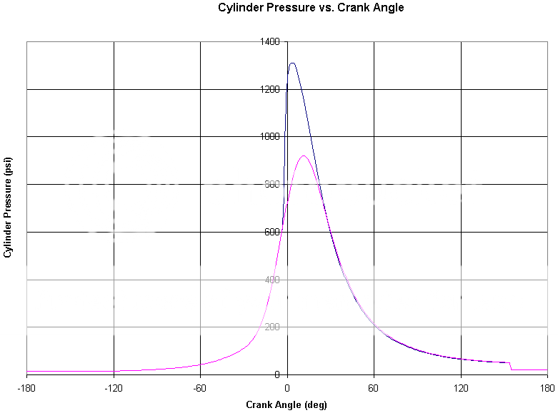
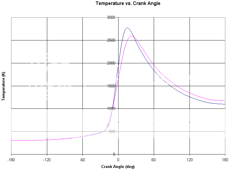
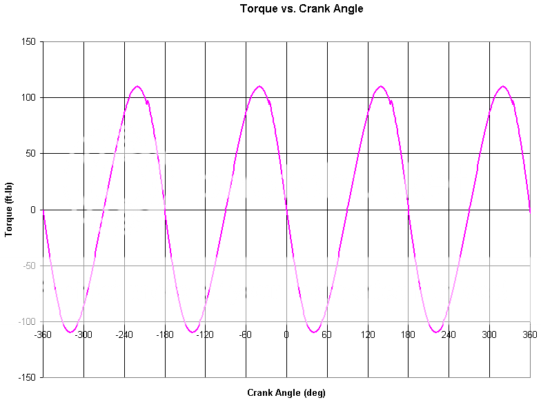
Here are some graphs to help you understand this visually. Here is what the cylinder pressure and torque traces might look like for a hypothetical naturally aspirated D16:

D16_Pressure1_Labeled1.png

D16_Torque1.png


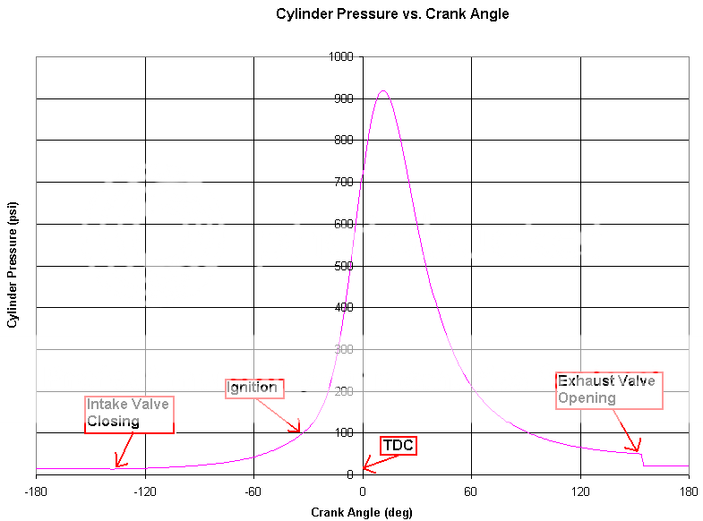
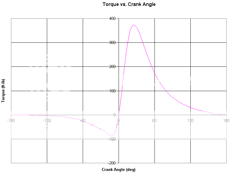
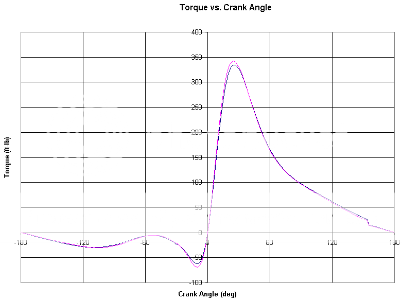
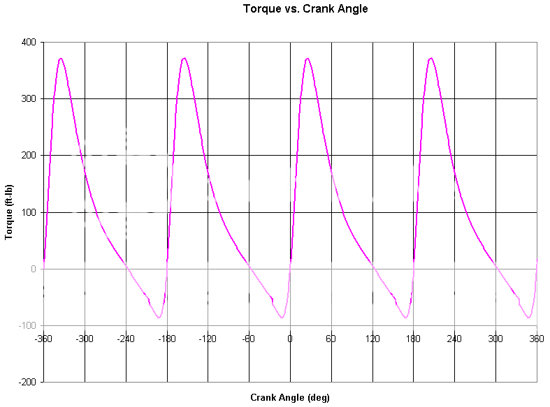
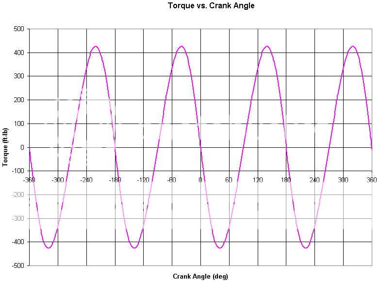
Notice how the torque at TDC (0 deg) is 0 ft-lb even though the cylinder pressure is more than 700 psi. Furthermore, the average torque produced by this cylinder is only 23 ft-lb over a 720 degree period, yet there is a 370 ft-lb spike in the power stroke and a -88 ft-lb dip in the compression stroke. Since this is only one cylinder of four, let’s overlay this trace with the other three cylinders to see what the sum of their contributions is:

D16_TorqueAll1.png


Since our engines use single-plane crankshafts, torque will always be zero whenever a piston is at TDC or BDC, neglecting the effect of rotational inertia.

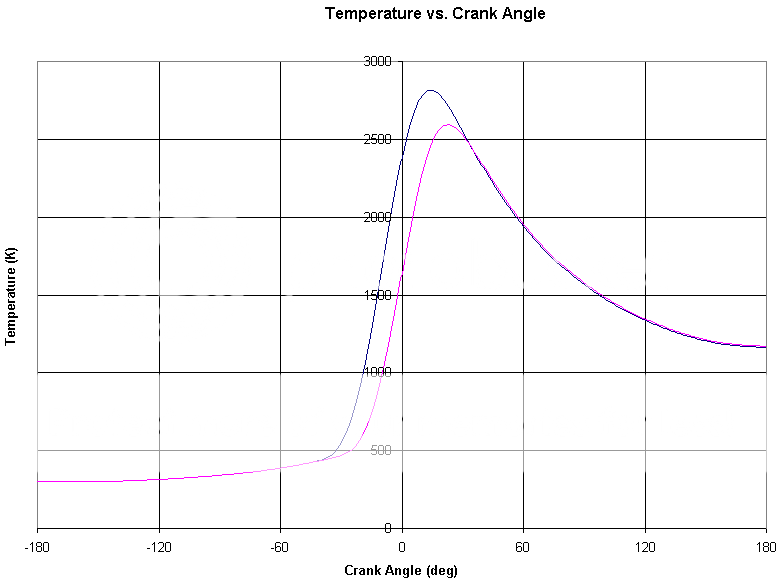
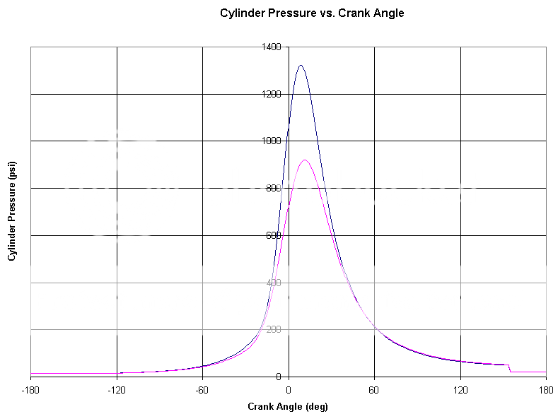
At low speeds, the forces created by combustion are responsible for almost all of the torque created about the crankshaft. However, as the engine starts to rev higher, the inertial forces of the pistons, rings, wrist pins, and small ends of the connecting rods grow exponentially and do weird things with the torque trace. Whenever a piston is at TDC, it has to change directions, which means its acceleration grows immensely. Since the piston, rings, wrist pin, etc. have mass, this creates a force in the connecting rod, which is then transferred to the crankpin. Here is a graph showing how these inertial forces create torque about the crankshaft in our hypothetical D16 at 4000 rpm:

D16_TorqueAll-Inertial1.png


The mean torque is zero, but the spikes are pretty significant. Let’s see what happens if we double the engine speed and rev to 8000 rpm:

D16_TorqueAll-Inertial2.png


Notice that the torque spikes quadrupled in amplitude even though we only doubled the engine speed. This is because the piston’s acceleration grows exponentially with the crankshaft’s rotational speed. At low speeds, it has a small effect, but at high speeds, this put a lot of force in the connecting rods. Luckily, combustion actually helps to damp out these spikes. Let’s see what happens when we put the combustion forces into the mix:

D16_TorqueAll-Inertial3.png


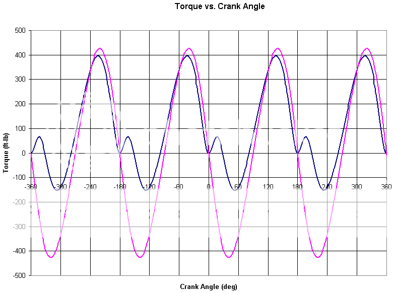
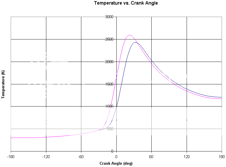
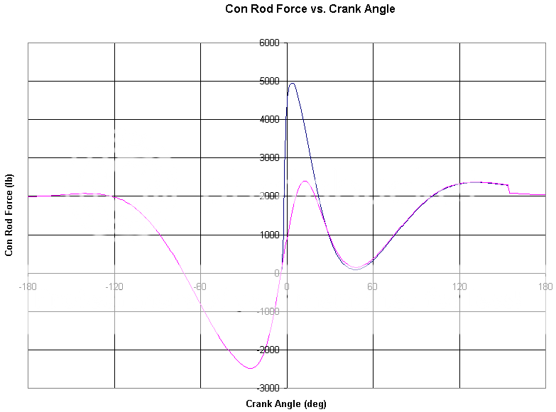
In this graph, the blue line represents the sum of the torques created by combustion forces and inertial forces, and the pink line represents the torque created only by the inertial forces. The large spikes in the blue trace are caused by the pistons decelerating near TDC, which puts tension in the connecting rods and “pulls” the crankpins toward the top of the bores. The dips in the trace are caused by the pressure created by burning mixture cancelling out a large portion of the tension that would exist in the connecting rods as the crankshaft tries to accelerate the pistons back down the bore. When you think about it, the burning fuel isn’t really what’s making torque at high speeds; it’s the pistons themselves trying to slow down as they approach TDC and BDC. To get a better idea of this, let’s look at the force in the connecting rods at this engine speed:

D16_ConRodForce-Inertial1.png


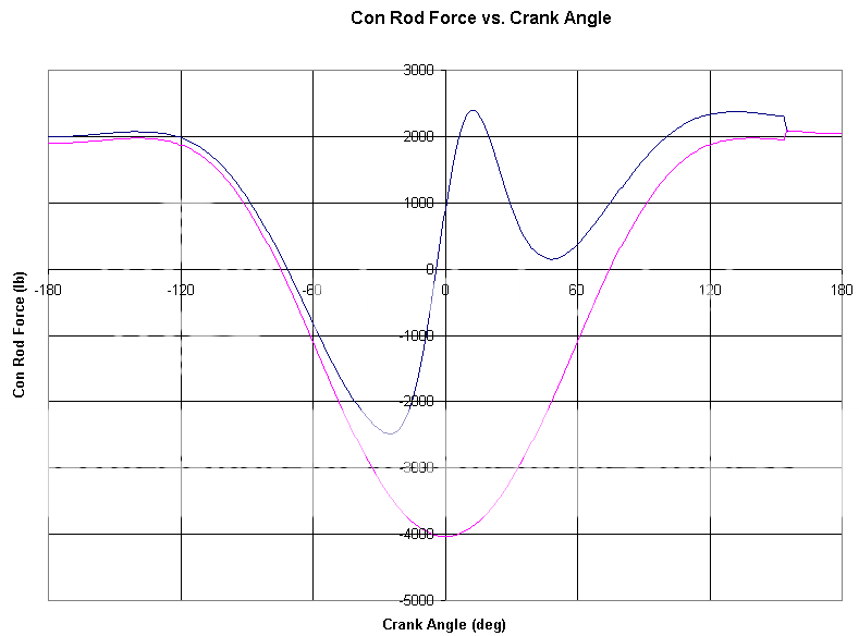
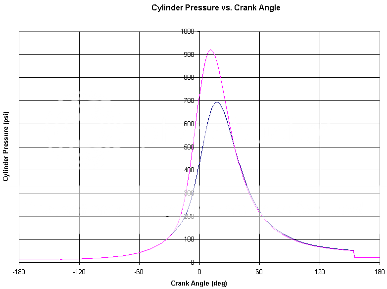
In this graph, positive force loads the connecting rod in compression, and negative force loads the connecting rod in tension. Before TDC (0 deg), tension will create positive torque, and after TDC, compression will create positive torque.

Notice that when there is no fuel being burned (for example, during fuel cut after you lift off the throttle), the magnitude of the force in the connecting rods is almost twice as high near TDC as it is when combustion occurs. This is because the combustion forces create a “cushion” that counteracts the inertial forces of the pistons. Remember this next time you think about closing the throttle at redline…
 
Last edited:

Full_Tilt

forum member
Joined
Jan 20, 2011
Posts
1,697
Reaction score
1
Part 2

Ignition Timing

Since the fuel in the cylinders doesn’t burn all at once, the spark needs to ignite the mixture at some point before 10 deg ATDC to optimize mean torque output. At this point, there is a perfect balance between cylinder pressure created early in the power stroke and cylinder pressure created during the compression stoke, opposing the crankshaft’s motion. If timing is advanced beyond this point, too much pressure is created before the piston reaches TDC, and if timing is retarded beyond this point, too much heat energy is lost out the exhaust. The name for this point is commonly referred to as MBT. There are several terms for this acronym floating around including Maximum Brake Torque and Mean Best Torque. Don’t get too hung up on the term, because its meaning is much more important.

Let’s take a look at what happens when we advance our hypothetical D16 by 10 degrees more than MBT. In the following graphs, the engine running MBT timing is shown in pink:

D16_Pressure-MBT1.png

D16_Temperature-MBT1.png


When the timing is advanced past MBT, cylinder pressure and temperature both rise much higher than necessary to produce the given mean torque output. This puts a lot more stress on the engine, makes the piston crowns and combustion chambers hotter, and reduces engine life. Since the temperature is so high, heat is also lost more quickly to the water jacket, and thermal efficiency drops. Furthermore, if you have to worry about passing emissions tests, over-advanced ignition timing will raise your NOx and CO emissions as the higher temperatures and pressures will cause oxygen atoms dissociate from carbon dioxide and bond with nitrogen atoms (or nitrogen oxide molecules).

Let’s take a look at what happens when we retard our hypothetical D16 by 10 degrees less than MBT instead:

D16_Pressure-MBT2.png

D16_Temperature-MBT2.png


In this case, cylinder pressure is significantly reduced and temperature is much lower until about 35 deg ATDC. Therefore, there is much less stress on the engine, and less heat is lost to the water jacket. However, since the burn was started much later in the cycle, the temperature toward the end of the power stroke is higher, more heat energy is lost to the exhaust, and thermal efficiency drops.

In general, retarding ignition timing is much safer than advancing it. However, keep a close eye on your EGT, because it will start creeping up too much if you’re not careful.

Another reason to only run as much ignition advance as necessary is to prevent detonation (AKA knocking). So what is detonation anyway?

Detonation

Detonation is the spontaneous ignition of some portion of unburned fuel in the cylinder. It occurs when the local pressure and temperature in the cylinder exceed the autoignition conditions for the fuel, and the mixture begins burning before the flame front reaches it. If only a small portion of the unburned mixture detonates, the knocking is considered light, and it will have a negligible effect on engine life. In some cases, light knocking could actually be desirable from an efficiency standpoint, but I wouldn’t recommend tuning this way unless you really know what you’re doing. On the other hand, heavy knocking will significantly increase cylinder pressure and temperature, leading to broken ringlands, melted pistons, and in really bad cases, broken connecting rods. If it wasn’t already obvious, you should NEVER tune for heavy knocking.

Here is a crude example of what heavy knocking can do to cylinder pressure and temperature. In the following graphs, the pink trace represents normal combustion, and the blue trace represents an engine that is knocking:

D16_Pressure-Knocking1.png

D16_Temperature-Knocking1.png


In this case, knocking increased peak cylinder temperature by 800°F and peak cylinder pressure by 400 psi. Let’s see how this affects the force on the connecting rod:

D16_ConRodForce-Knocking1.png


Uh oh... The connecting rod force in the knocking engine is about twice as high as the force in the normally running engine. Its magnitude is even higher than the case I showed earlier, when no fuel is being burned in the cylinder. This already can’t be good for engine life, but now imagine if the engine was turbocharged…

Detonation is always a concern with high performance engines because it works against our basic objective: maximize cylinder pressure early in the power stroke. When we improve VE, use forced induction, etc., peak cylinder pressure and temperature always increases (all else being equal). This is great for power, but it also welcomes detonation.
 

Full_Tilt

forum member
Joined
Jan 20, 2011
Posts
1,697
Reaction score
1
Part 3

Compression

One of the key parameters of any engine is its compression ratio. You probably already know that more compression will make more power (within reason), but it will also make the engine more likely to knock. Let’s take a closer look at what happens by increasing the static compression ratio of our hypothetical D16 to 12:1, represented by the blue traces in the following graphs.

D16_Pressure-CR1.png

D16_Temperature-CR1.png


The engine with the higher compression ratio has a much higher peak cylinder pressure and a noticeably higher peak cylinder temperature, which makes detonation more likely to occur.

The key to understanding why raising the static compression ratio will improve torque output is looking at the temperature plot. Do you see how the cylinder temperature becomes lower after ~25 deg ATDC? This is because the gasses are expanding more, and more energy is used to create torque instead of being lost out the exhaust. For this reason, an engine will perform better with slightly smaller exhaust primaries when you increase its static compression ratio. Of course, this is assuming the primary size was already optimized before increasing the static compression ratio.

However, since the peak temperature is noticeably higher, a slightly larger portion of heat energy is lost to the cooling system. Even still, overall thermal efficiency will improve with diminishing returns as the compression ratio is further increased (all else being equal). This means that increasing an engine’s compression ratio from 7:1 to 8:1 will result in a larger gain than going from 14:1 to 15:1.

Rod Ratio

Rod/stroke ratio is a buzz term that has been subject to debate for many years. Some people claim that a higher rod ratio will make more power, others claim the ideal rod ratio is 1.75:1, and some others claim that it doesn’t make any measurable difference. Who’s right, and why?

Changing the connecting rod length will not change cylinder displacement or mean piston speed, but it will change the piston displacement, velocity, and acceleration at every crank angle. How does this affect torque and efficiency? Let’s again take our hypothetical D16 and increase its rod length to 157mm to give it the supposedly optimal rod ratio of 1.75:1. Let’s also drop the engine speed to 3000 rpm so the effects are clearer. In the following graph, the blue line is the engine with the 1.75:1 rod ratio.

D16_Torque-RodRatio1.png


At first glance, it might look like the engine with the shorter connecting rod performs better. However, the mean torque is actually slightly lower than the engine with the longer rod, and the brake-specific fuel consumption is higher. Let’s try another case. Let’s increase the rod length to 200mm to give the engine a motorcycle-like 2.22:1 rod ratio. I won’t show the graph, but this change results with the engine producing less torque, even though brake-specific fuel consumption is still better. What’s going on?

First, since the intake valve is closing after BDC, changing the rod ratio will change the mass of air/fuel mixture trapped and burned in the cylinder. In this case, the longer rod will trap less air/fuel mass because the piston moves faster away from BDC and the cylinder volume at the intake valve closing (IVC) event is lower.

Next, since there is more dwell near TDC, the engine with the longer rod makes best torque with slightly less ignition timing. Another reason it needs slightly less ignition timing is because the ratio (which I’ll call mechanical advantage) of torque created about the crankshaft to force developed on the piston and is higher later in the cycle. To illustrate this, take a look at the following graph. The pink line is an engine with a 1.11:1 rod ratio, and the blue line in an engine with a 2.22:1 rod ratio.

D16_MechanicalAdvantage1.png


Since energy is being used more efficiently to create torque, this also means the friction losses between the piston/ring package and cylinder wall will be reduced. Therefore, cylinder wall, piston skirt, and ring package wear will be reduced (all else being equal).

So what’s the optimal rod ratio, if it even exists? Without changing ignition timing and without maintaining a near-equal trapped air/fuel mass, an ideal value seems to exist at ~1.7:1.

RodRatioStudy.png


Even though a clear peak exists, the difference between one rod ratio and another is extremely small. However, if ignition timing and IVC are changed along with rod ratio to ensure ignition timing is always MBT and the trapped air/fuel mass is always the same, the trend changes:

RodRatioStudy2.png


Based on this analysis, a longer rod is better for both power and BSFC at steady-state. However, there are diminishing returns past 2:1. Furthermore, higher rod ratios will require taller, heavier engines and heavier connecting rods. Not only are the rods physically longer, but their cross-sectional area will have to be increased to improve buckling strength. This means the car will weigh more and more energy will be required to accelerate the crankshaft. After a certain point, overall performance will be reduced.

Disclaimer

I made a “simple” Excel spreadsheet to generate the graphs in this article. Since it’s only an Excel spreadsheet (and since I’m not employed by Ricardo, Gamma Technologies, or AVL), I had to make a lot of assumptions. For example, some of you probably noticed my gross simplification of exhaust blowdown, but since that’s fairly complicated to model, I didn’t want to kill myself with hours of math. For that reason, my numbers are not completely accurate and should not be interpreted as experimental data. However, this does not mean the trends I presented are invalid.

For those of you who are interested in this sort of thing, all of the concepts and equations I used can be found in Gordon Blair’s Design and Simulation of Four-Stroke Engines. It’s a little expensive, but it’s my favorite book on engine design. Be forewarned that it’s very math-heavy and is not recommended for small children or people with high blood pressure.

That’s all I have for now, but I’m planning on making other articles like this one if people seem to like it.

If I recall correctly this user did make a few other write-ups such as this, one in particular about torque volume and gearing that many of you would probably find informative. Especially since I still see the 'torque vs power' debate...
 

TexasKyle

D.I.L.L.I.G.A.F
S197 Team Member
Joined
Jun 19, 2007
Posts
3,039
Reaction score
38
Location
Katy, Tx
Glad someone liked it.
I know this isnt old news to everybody, but I guess nobody cares, haha

It's nice to have all that in one place for people to look at. Most people, me included, don't think about all those aspects when we think of our engines and how they operate.
 

Support us!

Support Us - Become A Supporting Member Today!

Click Here For Details

Sponsor Links

Banner image
Back
Top