Planning a Ford Racing “Aluminator” Build with associated mods over the winter

Scott

Senior Member
Joined
Nov 17, 2009
Posts
2,337
Reaction score
44
Location
King City, Ontario, Canada
Placed a level to span the trunk floor and the ground. Measured from the level to the trunk floor and to the ground to determine the locations for the holes in the back panel and bumper cover. Marked and drilled 1/8 pilot holes in the back panel and bumper cover.

Placed a trouble light inside the trunk and took a peak through the hole in the bumper cover and voila I see the light. Slipped a welding rod through the two holes and it looks like my alignment should be good to go.


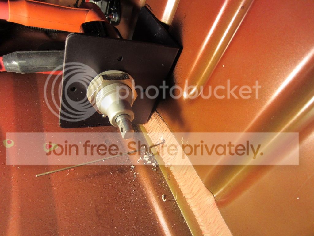
Drilled the back panel and the bumper cover with a step bit to just over ½” and trial fitted the push off rod.


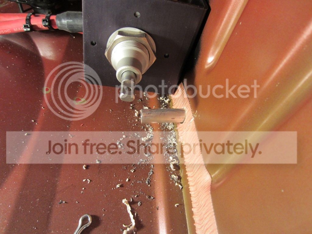
A significant amount of adjusting (grinding) needs to be done to the back panel hole as the disconnect switch swings in an arc and as well the shaft moves in and out as the switch is disengaged/engaged.
 

Kidd

Senior Member
Joined
Sep 2, 2010
Posts
2,131
Reaction score
5
Location
Berea KY
Any more pics or maybe videos of your car Scott? From the side view in your sig that is the best looking S197 car I have ever saw! last time I was very active on here you had just installed the Airlift kit. you've done an amazing job on this car, I will be reading through this thread for sure.
 
Joined
Mar 7, 2011
Posts
498
Reaction score
5
Location
Northwest Subs Chicago
Kurt thanks, I was following Todd’s (tmcolegr) battery relocation thread pretty closely and he documented it very well. Basically I ran a 1 gauge 200 amp fused positive to a distribution point in the passenger tire well, a 4 gauge 150 amp fused positive directly to the alternator and a 1 gauge ground to the OEM chassis ground location. I just reviewed my build documentation and I actually relocated the battery to the trunk in May 2012, it was the Optima D34 battery I added in March 2013.

Great.. thanks Scott, I looked up that thread and started to search parts will do the same route. I found some nice breakers I'm going to try instead of the Fuses but sticking to the rest of the diagram.
http://www.ceautoelectricsupply.com/circuitbreakers.html
8B3EniP.jpg
 

Scott

Senior Member
Joined
Nov 17, 2009
Posts
2,337
Reaction score
44
Location
King City, Ontario, Canada
Great.. thanks Scott, I looked up that thread and started to search parts will do the same route. I found some nice breakers I'm going to try instead of the Fuses but sticking to the rest of the diagram.
http://www.ceautoelectricsupply.com/circuitbreakers.html
8B3EniP.jpg

Kurt the breakers are a neat idea, made me think as I currently do not carry any extra fuses in my car.

Not the best picture, but I mounted my fuses directly on the battery box and that would probably be a good location for the breakers.


Scott

Senior Member
Joined
Nov 17, 2009
Posts
2,337
Reaction score
44
Location
King City, Ontario, Canada
Any more pics or maybe videos of your car Scott? From the side view in your sig that is the best looking S197 car I have ever saw! last time I was very active on here you had just installed the Airlift kit. you've done an amazing job on this car, I will be reading through this thread for sure.

Thanks Sam! Sorry no video and there are a few more pictures of the car in this thread.

Some of the mods that come to mind after the Air Lift install are:

- Boss 302 X-Brace and rear seat delete
- Corbeau Harness Bar
- CDC GT/CS Illuminated Door Sills
- BMR Upper Control Arm Mount
- Pioneer ND-BC6 Backup Camera
- GT500 Front Splitter
- Replaced the 3" Magnaflow exhaust with a 3" MBRP system (the MBRP is about 3/4" more friendly to lowered cars.

And of course the new differential, narrowed 1" per side, welded tubes with Strange 35 spline spool, axles and C-Clip Eliminators. With the narrowed differential I am able to tuck the drag radials in with the suspension aired-out. In my signature picture the car is being held up by the over-axle pipes resting on the differential.


Scott

Senior Member
Joined
Nov 17, 2009
Posts
2,337
Reaction score
44
Location
King City, Ontario, Canada
Battery Disconnect Switch - Continued

Trial engaged and disengaged the disconnect switch marking with a felt pen, adjusting the back panel hole with a Dremel and carbide burr double cut bit until the rod would move freely without binding.

This is the hole I ended up with.


Splashed on a little flat black primer to protect the bare metal.


Marked the travel between engaged and disengaged on the push pull rod and determined the 18” rod needed to be cut down to approximately 7-3/4”. Cut the rod with a 6” chop saw, punched and drilled the cut end about 1-1/4” deep with a 1/8” then a ¼” bit (should have used a 17/64” bit for use with a 5/16-18 tap but I did not have one). Using a 5/16-18 tap tapped the hole and installed the 5/16 set screw, jam nut and “T” handle. Finished it off by giving it a quick buff.


Will install the switch tomorrow when the primer dries.
 

Kidd

Senior Member
Joined
Sep 2, 2010
Posts
2,131
Reaction score
5
Location
Berea KY
Thanks Sam! Sorry no video and there are a few more pictures of the car in this thread.

Some of the mods that come to mind after the Air Lift install are:

- Boss 302 X-Brace and rear seat delete
- Corbeau Harness Bar
- CDC GT/CS Illuminated Door Sills
- BMR Upper Control Arm Mount
- Pioneer ND-BC6 Backup Camera
- GT500 Front Splitter
- Replaced the 3" Magnaflow exhaust with a 3" MBRP system (the MBRP is about 3/4" more friendly to lowered cars.

And of course the new differential, narrowed 1" per side, welded tubes with Strange 35 spline spool, axles and C-Clip Eliminators. With the narrowed differential I am able to tuck the drag radials in with the suspension aired-out. In my signature picture the car is being held up by the over-axle pipes resting on the differential.

That's wild that the ota pipes are the only thing restrictions it from going lower. I'm very interested to read up on this narrowed diff, might be something I look into for mine if it doesn't get traded off.
Like I said, excellent job sir. The car looks just nasty laid out on the bigs and littles tucking the drag radials[emoji106]

Sent from my SAMSUNG-SM-G900A using Tapatalk
 

Scott

Senior Member
Joined
Nov 17, 2009
Posts
2,337
Reaction score
44
Location
King City, Ontario, Canada
Battery Disconnect Switch – Done and Dusted

Primer was still tacky after drying overnight, although we have been having record high temperatures in December it still was not warm enough for the primer to dry according to the can label. On second thought this may be a good thing as the foam I am sticking over the hole may adhere better.

Installed the switch in the bracket, connected the shortened push pull rod and stuck some ½” thick foam on the back panel to cover the whole. Would have preferred to use a bellows style grommet like this, but there just is not enough room with the switch bracket mounted directly to the rear panel.

http://www.ebay.ca/itm/Seals-it-4-Series-Grommet-2-O-D-400-I-D-Bellow-Style-GS50238-/221595568694

I could not get the roll pin provided by Flaming River to slip through the switch so I settled for a cotter pin. Will need to try again in the spring to install the roll pin.

Disconnect switch in the off position.


Disconnect switch in the on position.


Disconnect switch in the off position.


Disconnect switch in the on position with the picture taken from the edge of the bumper. How do you like my garage slipper and PJ paints?


skwerl

tree hugger
Joined
Aug 6, 2011
Posts
16,333
Reaction score
1,313
Location
central Florida
I'm really surprised with as precise as all the other mods are on this car, that Scott just rattle can sprayed primer all over the place without any concern for overspray. I would have guessed it would have been masked off or else the entire trunk repainted.
 

Scott

Senior Member
Joined
Nov 17, 2009
Posts
2,337
Reaction score
44
Location
King City, Ontario, Canada
That is a great location for the cutoff, very nice work Scott

Thanks Josh! I can't take credit for the location, as far as I know Todd (TMCOLEGR) was the first to pioneer that spot.

Looks great, you do some really nice work Scott.

Thank you Scott!

I'm really surprised with as precise as all the other mods are on this car, that Scott just rattle can sprayed primer all over the place without any concern for overspray. I would have guessed it would have been masked off or else the entire trunk repainted.

Brain, paint is the worst part of my car, needs a good restoration job. Let me say I used very short bursts closer than recommended to the panel. While out of the garage holding the can upside down to clear the nozzle took a lot longer than spraying the panel. Ok ok, I was just too lazy to tape everything up!

The roll pin wouldn't go all the way into my switch either. Looks great though!

Thanks Kyle, we may both need to try the roll pin in the freezer and a heat gun on the end of the switch shaft.
 

Scott

Senior Member
Joined
Nov 17, 2009
Posts
2,337
Reaction score
44
Location
King City, Ontario, Canada
Conversion to BMR Adjustable A-Arms with 19mm Tall Ball Joints – Continued

For progress so far see posts # 537, 539, 546 and 549.

Broke the front wheel nuts loose, jacked the car up, placed stands under the sub frame connectors and removed the tires.


Using a couple flat blade screwdrivers and a plastic/rubber tipped hammer pried the dust caps off.


Removed the brake anchor plate bolts with an 18mm socket and ½ ratchet. Supported the caliper so as not to stress the brake hose and removed the rotor.


Disconnected the wheel speed sensor and cooling duct bracket bolts with a 10mm ratchet wrench.


Removed the wheel hub nut and removed the hub.


Using an 18mm deep socket with a breaker bar removed outer tie rod end nut.


Tapped the tie rod end out with a few blows from a brass hammer.


Removed the upper spindle to strut bolts with an 18mm socket and breaker bar then a ratchet. Removed the ball joint bolt with an 18mm wrench on the nut and a 15mm socket on the bolt with a breaker bar then a ratchet.


2008 spindle removed (18mm ball joint hole).


2011 spindle slipped into place (19mm ball joint hole) and the strut to spindle bolts loosely installed.


Weather has turned cold and it looks like it is down on the concrete floor for me to re and re the A-Arms next time I have garage time.
 

Scott

Senior Member
Joined
Nov 17, 2009
Posts
2,337
Reaction score
44
Location
King City, Ontario, Canada
Got a little more garage time and a bit more done.

The two steering rack nuts were backed off using a ¾” wrench. This was required to permit raising the steering rack enough to remove the passenger side front A-Arm bolt. With a 22mm wrench and 22mm socket and breaker bar the rear and front A-Arm bolts were removed.

My original BMR A-Arm standard height 18mm Ball Joint, part number AA010 (early design) on the right and the BMR adjustable A-Arm with 19mm tall Ball Joint, part number AA026 on the left.


The adjustable A-Arms were installed using a new BMR hardware kit, part number RH014.


Using new hardened steel flat washers the four rear 22mm A-Arm bolts (2 per side) were tightened to 125 ft-lbs. The two front bolts will be tightened later with the chassis loaded.

The A-Arm tall ball joints were inserted into the spindles using new bolts, part number W711123-S439 and nuts, part number W520214-S440. Using an 18mm wrench and 15mm socket the ball joint cross bolts were tightened to 85 ft-lbs.


Maximum Motorsports strut to spindle mounting hardware kits part number MMF-3 was used to secure the struts to the spindles. These bolts were tightened to 148 ft-lbs.


The wheel speed sensors and cooling ducts were installed and tightened with a 10mm wrench.


Inner tie rod shafts were shortened by four threads with a Dremel and cut off wheel. The tie rod ends were threaded back onto the shafts and inserted into the spindles. New nuts were used, part number W705606-S440 and using an 18mm socket and 8mm wrench the nut was tightened and then torqued to 59 ft-lbs using a 18m deep socket.


The wheel hubs were installed and the nuts, part number F3LY-3B477-A were tightened to 2011 specifications, 251 ft-lbs with a 36mm socket.


Scott

Senior Member
Joined
Nov 17, 2009
Posts
2,337
Reaction score
44
Location
King City, Ontario, Canada
New dust caps, part number F1VY-1N135-A were installed using a 1-7/8” socket and a rubber mallet.


Baer brake rotors were slipped on and held in place with three open-ended lug nuts.


Brake caliper anchor plates were installed and the mounting bolts tightened to 85 ft-lbs with an 15mm socket after applying a little medium strength Loctite on the threads.


Trail fitting Vossen CV3R (20 x 9 +32.5) in Graphite finish for caliper clearance. No issues with Baer 6P calipers or with the TPMS valve stems.


tigerhonaker

Senior Member
Joined
Apr 11, 2009
Posts
6,516
Reaction score
30
Location
TN
Scott,

You provide excellent documentation on everything you do.
icon14.gif


Terry
 

Latest posts

Support us!

Support Us - Become A Supporting Member Today!

Click Here For Details

Back
Top