
Actually, all I want is a video of your face when you hit the kill switch and nothing happens.
I would like to see that too. I think it would look something like this
 or
or 
Actually, all I want is a video of your face when you hit the kill switch and nothing happens.
or  LOL
LOLLol, I don't bet if I'm not 100% sure I will win. Since I have already run the car, watched the switch successfully kill the car, I gotta say, I'm pretty confident I would win. I think my face will look more like

Then you dont have it hooked up like you said you were going to hook it up. You have it hooked up like the diagram you posted.


Are there any other wires then the three large ones attached to the switch. Seems to me the car wouldnt start this way but, would remain running if the switch was engagedThink you're missing what I'm saying. The car is already running, has been for months, wired just like I said, and have tested it successfully. Single bottom terminal you can see goes to the far right to the positive side. The top terminal has the small cable on it along with the 1/0 that goes to the front of the car. Is this not wired exactly like I said it was ?
I don't think you are , there are clearly two different ways of wiring this switch according to the post here . If they both work, so be it. I don't see how only isolating the battery can kill the car when we all know the alt will run the car with the hot cable disconnected from the battery.Not gonna mess up the OP's thread any further. Pardon us tmcoleger
I couldn't find a wiring diagram when I was doing this of the alt. All you have to so it kill the power to the stator, and the alt turns off. I wasn't sure it would work either. But I figured if I was wrong, a few turns of the nut and I could swap terminals. There aren't any other wires to the switch. There are some you see there from the water pump, boost a pump and what not. But eh, it worked so I'll leave it.Are there any other wires then the three large ones attached to the switch. Seems to me the car wouldnt start this way but, would remain running if the switch was engaged
Are there any other wires then the three large ones attached to the switch. Seems to me the car wouldnt start this way but, would remain running if the switch was engaged
I don't think you are , there are clearly two different ways of wiring this switch according to the post here . If they both work, so be it. I don't see how only isolating the battery can kill the car when we all know the alt will run the car with the hot cable disconnected from the battery.
I couldn't find a wiring diagram when I was doing this of the alt. All you have to so it kill the power to the stator, and the alt turns off. I wasn't sure it would work either. But I figured if I was wrong, a few turns of the nut and I could swap terminals. There aren't any other wires to the switch. There are some you see there from the water pump, boost a pump and what not. But eh, it worked so I'll leave it.
Not gonna mess up the OP's thread any further. Pardon us tmcolegr
I'm not sure if there is enough delay in the 12v source running back to the pcm to keep the alt turned on or what.CPRsm, The thinking here is from everything a car guy has ever seen . When the + 12v is disconnected the alt is running the car. If the alt. 12v is disconnected at the same time as the batt. then the car will die. The way you have it the alt. should keep the car running. IMO
No worries. Figured it would throw people thru loops but seemed easier than your originally planning. Although at the time I didn't see the diagram for some reason. You should be able to easily test it out on yours if wanted to verify it yourself. I'd be curious myself.I am not going to spar with CPRsm and his method, although for the life of me I don't see it working as described, but that's neither here nor there. I'm not there so I can't confirm his setup will or won't work. Nonetheless I will be using GB10s setup as I clearly can see how it will work.
CPRsm no disrespect intended.
After mine is cranked I will test both ways. Inquiring minds must know the answer. LOLI'm not sure if there is enough delay in the 12v source running back to the pcm to keep the alt turned on or what.
No worries. Figured it would throw people thru loops but seemed easier than your originally planning. Although at the time I didn't see the diagram for some reason. You should be able to easily test it out on yours if wanted to verify it yourself. I'd be curious myself.
Not a problem. My opening post clearly asked for ALL opinions, pro or con. Be careful what you ask for. But hey, that's how we all learn. Look at the way I was originally intending to move forward - fortunately someone chimed in with another method that is much simpler and cleaner to install.
I am not going to spar with CPRsm and his method, although for the life of me I don't see it working as described, but that's neither here nor there. I'm not there so I can't confirm his setup will or won't work. Nonetheless I will be using GB10s setup as I clearly can see how it will work.
CPRsm no disrespect intended.
PS: I have slightly altered my decision on where to mount the disconnect switch - you'll either like it or hate it. I have spent hours looking at the back of the vehicle trying to find the cleanest location to penetrate the trunk compartment that won't allow water to enter anywhere. Since this is a very limited street use vehicle, I also want the knob and lever to be aesthetically appealing.
Your posts and build have been helpful to so many of us, but I thought you weren't going to race your car.
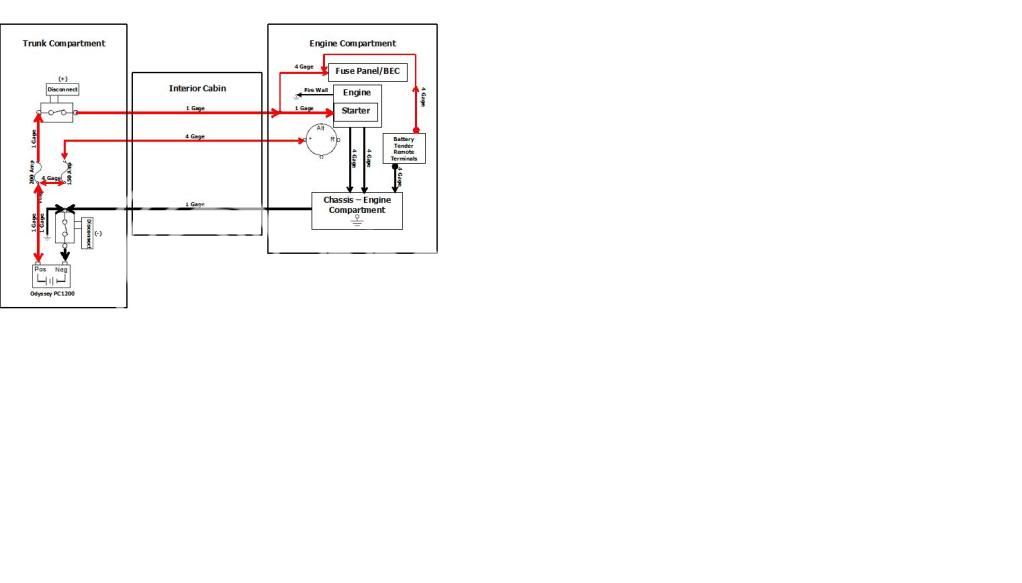
Any particular reason for not running 1 ga all the way to the starter, or at least 4 ga? 6 for that last bit just sounds . . . a little light.
Is 200A enough for full starter draw under unusual circumstances?
Norm


