Alexmaya07

Junior Member
Joined
Nov 27, 2022
Posts
24
Reaction score
1
Location
Swfl
Got an 11’ finally put back together, built motor gen2 block, t56 swap with bowler harness, vmp supercharged, fore innovations triple pump . Car cranks over, throws fuel but no ignition spark, checked all grounds, changed wiring harness, changed to new coils, new plugs, had pcm reflashed, checked all relays, fuses and can’t figure out why no spark at all. I get no voltage to the coil, no voltage to the connector. I need help!
 

Alexmaya07

Junior Member
Joined
Nov 27, 2022
Posts
24
Reaction score
1
Location
Swfl
Changed crank sensor twice just cause i thought maybe the new one i got was defective and replaced with a new one again. I get no constant power to any coil connector. Tune is uploaded and even went to old tune to see if it’ll fire up and nothing.
 

86GT351

forum member
Joined
Nov 14, 2010
Posts
6,045
Reaction score
909
Location
Sunny South Florida
Something simple possibly. Check fuse F40 in the Battery Junction box. It is a 15Amp fuse in the Battery Junction Box,
upload_2022-11-28_14-30-9.png
 

Alexmaya07

Junior Member
Joined
Nov 27, 2022
Posts
24
Reaction score
1
Location
Swfl
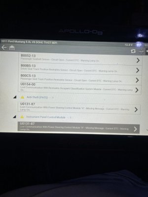
Ok, what about a pin out for the battery/powersteering/transmission harness. I took a battery cable harness off a 2014 coyote manual premium and used it on mine since I lost my original. Do you think it’ll affect the power steering(U0131-87 PATS) ?
 

86GT351

forum member
Joined
Nov 14, 2010
Posts
6,045
Reaction score
909
Location
Sunny South Florida
Ok, what about a pin out for the battery/powersteering/transmission harness. I took a battery cable harness off a 2014 coyote manual premium and used it on mine since I lost my original. Do you think it’ll affect the power steering(U0131-87 PATS) ?

It might. If it has CAN Bus any breakdown in communication between modules can create havoc
 

Alexmaya07

Junior Member
Joined
Nov 27, 2022
Posts
24
Reaction score
1
Location
Swfl
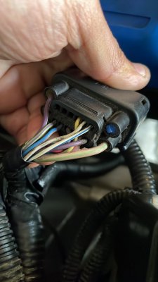
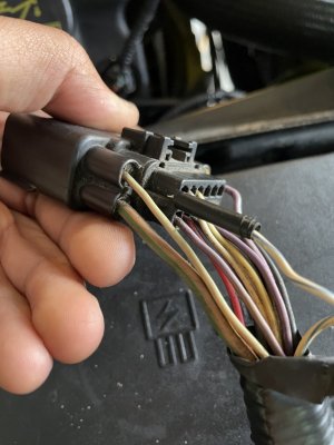
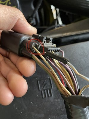
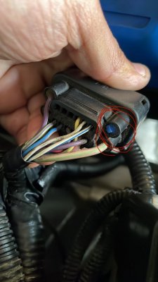
There is 1 wire missing in the harness off the 14’ so I don’t know if its anything critical

1D118306-C0F7-4580-AB0C-6994CABA6E14.jpeg

CA010B9E-E4E0-4C15-875E-D1BBEFDC7D60.jpeg
 

DieHarder

Senior Member
Joined
Nov 9, 2019
Posts
1,467
Reaction score
758
Ok, what about a pin out for the battery/powersteering/transmission harness. I took a battery cable harness off a 2014 coyote manual premium and used it on mine since I lost my original. Do you think it’ll affect the power steering(U0131-87 PATS) ?

Whatever cables/connectors you used (not original to the car) you'll need to compare/verify pinouts (point-to-point) for each one. Cabling usually doesn't change much from year to year but any differences must be noted and verified. Whatever changes you find in the cabling that don't agree w/the 2011 prints chase it to determine what those differences are/what it feeds/provides. I think I would start with that missing wire. You should be able to identify it in one of the online manuals and go from there.

Good luck.
 

DieHarder

Senior Member
Joined
Nov 9, 2019
Posts
1,467
Reaction score
758
Start here: https://iihs.net/fsm/?d=0

There are manuals for both the 2005 - 2010 & 2011. They can be a bit kludgy to work with at times; some of the pages may be out of order so you may to do extra searching to find what you're looking for. I understand there are more online manuals; some manuals are arranged better than others.... Do a search or perhaps one of the other members will post some links.
 
Last edited:

redfirepearlgt

forum member
Joined
Mar 19, 2011
Posts
2,497
Reaction score
263
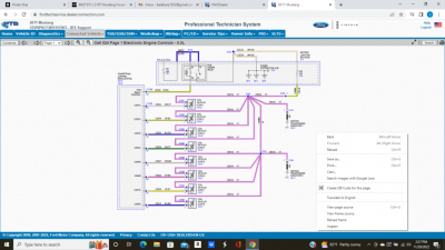
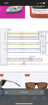
The white /blu stripe wire is the CANBUS+ and the WHITE is the CANBUS - on the bus. If that connector is C263 (C264 later model 11) then the White/blu stripe has to go back into pin 2. A break at this point would cause loss of coms to anti lock and steering systems as well as the PCM. The restraint messages are likely there since they communicate bot hon the CANBUS network and independently to the anti lock brake module. The same C263/4 connector also is a break point between ABS and restraint as well. See attached schematic.

https://iihs.net/fsm/?d=711&f=014 - Module Communications Network.pdf&p=3

But even fixing this does not validate that the two harnesses are interchangeable. Without knowing the exact connector number I can only spit in the wind at a guess here.

As for the no spark 86GT351 is correct, but if it is not blown also check F21 a 30A that is on the PCM relay.

PATS is active that may be the cause of the lack of spark as well. You show an alert for PATS anti-theft which puts the car in disabled mode.

Verify that you can use the later model harness. Then fix the wire that is clearly pulled out or get the proper cable. That will resolve your coms issues with CANBUS. Then see if PATS is still active. FI so you will need to reset that...not sure how myself as I have never had an issue with it.

If you open the link above it will allow you to go back to the online 2011 manuals overview.
 

Alexmaya07

Junior Member
Joined
Nov 27, 2022
Posts
24
Reaction score
1
Location
Swfl
Circled in Red is the wire I’m missing off the 14’ harness, and coming out of my fuse box that connector has that what appears to be white/green cable.

I will look into tonight see if pins are lining up, I will also check those fuses for ignition.

D0A1D1DC-1D54-4E30-BA5D-7278E825A995.jpeg

26AE2477-2CD0-441A-8744-0570C311B244.jpeg
 

Alexmaya07

Junior Member
Joined
Nov 27, 2022
Posts
24
Reaction score
1
Location
Swfl
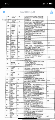
I have narrowed it down to the wire missing is the OSS sensor. All the other wires in the 14’ harness and the one coming from my fuse box connector line up perfectly. Now my question is would this throw that PATS code, like is it a CAN wire or whatever it is.

84BD3CA3-D1B6-4786-8599-2DEAEE0ECA6A.png

BC89DE28-20F1-44CB-BD67-BC0D8732DEAD.png
 

redfirepearlgt

forum member
Joined
Mar 19, 2011
Posts
2,497
Reaction score
263
Sorry I thought I saw a common thread in the diagnostic readout. There are coms issues on both the MS bus and HS bus. The harness you have may not be compatible. There were apparently 2 changes in the harness layout in the 201 model alone as there are several early and late model references where the connectors change name and sometimes even have a different location in the vehicle. Best of luck. I thought you were eluding to the white/blu stripe wire which is the common color on the HS+ CANBUS side the exception being the direct coms between the RCM and ABS modules.

Hopefully someone with "one-off" build experience (for no better term) may have some insight for you.
 

Alexmaya07

Junior Member
Joined
Nov 27, 2022
Posts
24
Reaction score
1
Location
Swfl
But I have confirmed I do get constant power to ignition coils when key is turned on. Buts looks to be grounding out somewhere or its the PATS code cause at initial key on it’ll be .19-.23 V but falls to .11-.12 V after few seconds . Then I conducted a test turning it over and it goes from .23V to .05-.01 like it instantly cuts power to the ignition.
 

Latest posts

Support us!

Support Us - Become A Supporting Member Today!

Click Here For Details

Sponsor Links

Banner image
Back
Top