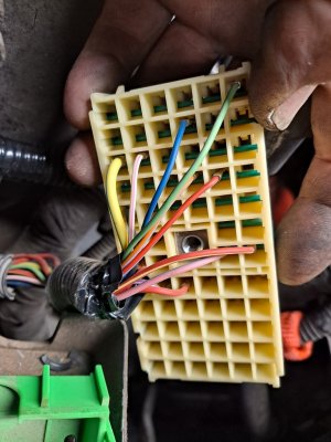

Diagram for Green Connector to Fuse Box?

AnotherS197GT

Serial Valve Dropper
Joined
May 4, 2011
Posts
5,981
Reaction score
33
Location
USA
Last edited:

NotQuik

I can't drive
Joined
Sep 2, 2007
Posts
2,705
Reaction score
2
Location
Central Florida
That's definitely not it....You had the right one the first time. I overlooked it being a c1045a instead of a "b".
 

NotQuik

I can't drive
Joined
Sep 2, 2007
Posts
2,705
Reaction score
2
Location
Central Florida
AnotherS197, just curious where you got the pdf's from?

I was thinking about it and wonder if since I was comparing to a 2005 diagram and 2007 connectors....good chance there are differences there as well...
 

AnotherS197GT

Serial Valve Dropper
Joined
May 4, 2011
Posts
5,981
Reaction score
33
Location
USA
I got them from Ford. I work at a Ford dealer and pulled them right out of the WSM.
 

05stroker

Never enough power guy!
Joined
Mar 2, 2008
Posts
13,089
Reaction score
100
Location
Bullard Tx.
Looks to me like you have two wires in the wrong spots. All of your wires match the diagram in the Ford wiring diagram manual I have for n 06 except for the red with yellow and the double red wires. By my diagram the red with yellow should be at A6 and the double red should be at C5. The way you have it now the red with yellow is at F5 and the double red at D5. Also if you have a manual trans then there should be a VT/YE wire in the D5 spot where you have the double red now. Both D5 and C5 are 12v in start and run though.
 
Last edited:

05stroker

Never enough power guy!
Joined
Mar 2, 2008
Posts
13,089
Reaction score
100
Location
Bullard Tx.
That's getting closer..

Mine has no A6 and no B2.

On that one it looks like E5 would be the one in question, however it's a different color wire and appears to be "transmission overdrive cancel switch signal" (I'm assuming that's related to an auto, mine is 5 speed). The RD-YE appears to be "voltage supplied in start and run (overload protected) which is A6 and on the opposite side of the grid on mine? I'll take a look at my actual fuse box tonight and see if A6 would line up with anything, just to double check. I am fairly certain I'm not that far off though.

B2 in my manual shows to be a WH/LB circuit 294 12v all the time from the Buss fuse box to the SJB wich is the trigger wire for the ass delay switch.

Also another thing to remember is that he view in the manuals are of the bottom of the plug, conector side and not the side where the wires plug into the conector.
 
Last edited:

NotQuik

I can't drive
Joined
Sep 2, 2007
Posts
2,705
Reaction score
2
Location
Central Florida
I do see where you're coming from, and nor do I disagree.

Aside from the first pin which wasn't marked, all the others were. The process went with me putting a tally mark next to the pin, from the view posted they were all on the top side of the pin, and only one at a time was removed to prevent anymore possible confusion. If I knew I weren't diligent about that (aside from the RD/YE), i'd be questionnig them as well.

I'll see if I can run up to the dealer this week an have a buddy look up the Relay Information Diagram an Dynamic Systems Diagram for an 07...if not then i'll dig deeper into what you said.
 

NotQuik

I can't drive
Joined
Sep 2, 2007
Posts
2,705
Reaction score
2
Location
Central Florida
Thanks man...that'd be great.

I have a slightly unrelated question...I assume you used tie wraps to hold your fuse box in place or did you actually mount it with hardware and a bracket of some sort that you made?
 

rojizostang

i love my cams
Joined
Apr 26, 2008
Posts
5,505
Reaction score
20
Location
san antonio, texas
did you unpin those wires to remove some of the extra slack in the wiring harness after relocating the fusebox?

i just looped all the slack around the top of the fuse box before i strapped it in place.
 
Back
Top