JimC
Senior Member
- Joined
- May 5, 2007
- Posts
- 2,339
- Reaction score
- 720
Interesting - need to keep watching your progress on this.
Here's a side view using a 60 m/s flow stream of air over the top surface, and a high pressure region at the vent mouth:
http://www.leanangle.us/guest/sidevel.avi

^that....
If its recessed then I misunderstood.
*subscribed!!

It's about 107* here today and after installing a pair of GT500 mufflers and romping around a little, I am reassured that this project is worthwhile in a functional way. The car feels like a dog in the heat compared to a nice cool night and it is kicking off heat.

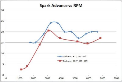
It's a nice balmy evening here so I decided to log another 2nd gear pull to compare data. I made a chart that plots spark advance vs rpm for that smoking hot day run vs tonight. It's no real surprise, but the ECU adds a significant amount of spark advance when IAT's are lower.
Now I need to get this vent built so I can see if it nets a real improvement during a blazing hot day.
It's interesting that the delta between ambient and IAT is so much different on the two days.
Still haven't heard back from the shop yet, so I'm going to stop by today.
I modeled a simplified version of the front half of a mustang. It's still pretty simple, and assumes the engine bay to be totally sealed (which it obviously isn't). But, it really shows that even with the vent installed, the high pressure region under the hood can reject quite a bit of incoming air, not allowing it to flow through the grill.
http://www.youtube.com/watch?v=72hyr-GueBo&hd=1
what if you moved the heat extractor closer to the front of the car where the high pressure is?
ok, i understand that, i know you said it was a quick mock up and the dimensions do not look to scale either.Well, that would defeat the purpose. You already have upper and lower grille openings in the high pressure, near the bumper. Like the latest CFD animation shows, at higher speeds the whole under-hood region becomes pressurized (which starts rejecting air from passing through the radiator).
By putting the vent where I intend, you use the low pressure (exterior) region along with the higher pressure under the hood to drive flow.
ok, i understand that, i know you said it was a quick mock up and the dimensions do not look to scale either.
it just seemed like the vent was a little too far back on the hood. i was thinking if it were placed behind the radiator over the throttle body where it looks as if the air is coming to a zero velocity (high pressure) that it may help it reduce the high pressure under the hood and take advantage of the fast velocity air (low pressure) to pull the pressurized air out from the engine bay.
going too far back on the hood you come to another high pressure point where the hood meets the windshield that would make it not work as well, but i am not sure at what distance back on the hood that would begin.
i guess what i'm trying to say is to model without the vent, then put the hood vent where the delta P is greatest from the inside to outside for it to work the best. the air in the simulation is at its highest velocity on the outside (where the pressure is lowest by looking at the darkest blue dots) closer to the front of the hood.
a bonus of this is it will also reduce front end lift at higher speed.