rlntlss
Junior Member
- Joined
- Feb 15, 2008
- Posts
- 4
- Reaction score
- 0
subscribing interesting thread


Yeah she wasn't real happy about the smellGreat job so far, Ron!
"What are you cooking, Honey?"...
"PISTONS"...lol
On a serious note, with a .020 over, just curious how much the coating added. Specifically, how thick was it and how many coats? Just wondering if it changed anything in the dome height?
") hehehehe
hehehehe wonder what i could use the toaster for?
wonder what i could use the toaster for?
finally got everything here. now i just have to file some rings and assemble. Just been busy maybe one day this week i can do the rings and then start getting this thing together.any updates?
That sounds like good generic advice, but given that the cams are pretty custom jobs, I would assume they came with a card which shows how they should degree up (and by extension where they should be set relative to the crank in a fixed setup).Set your cam locks in full retard. Cams and Ignition timing are just opposite. Full retard on the cams gives max power and torque.
LOL - My wife has become numb to random parts cooking in the oven - though I work hard to make sure they don't smell - haven't tried curing paint - that might get some questions and dirty looks...CK said:"What are you cooking, Honey?"...
isn't full retard on these like 50 or 60 degrees?Set your cam locks in full retard. Cams and Ignition timing are just opposite. Full retard on the cams gives max power and torque.
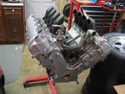
For the crankshaft, all truck cranks have an 8-bolt flange. Look at the casting/forging numbers. F75-IE or F75-E are forged. Everything else is cast.


isn't full retard on these like 50 or 60 degrees?
I haven't pulled the cam card out yet but they are ground 10* advanced on the billet. due the size and specs they couldn't fit them on the lobe design otherwise.
if the phasers are locked at full advance the cams (stock) should be 7 degrees advanced right? adding that to the 10degrees for my cams we get 17 degrees total advanced. depending on how they tell me to degree this thing how am i going to change the cam timing?
i've been told each tooth is 18degrees so i could do that but what if it only needs to be adjusted 8 degrees or something?
this part I'm leaving to someone else. I just don't have the experience with mod motors and if it's not done correctly it will be an expensive mistake.
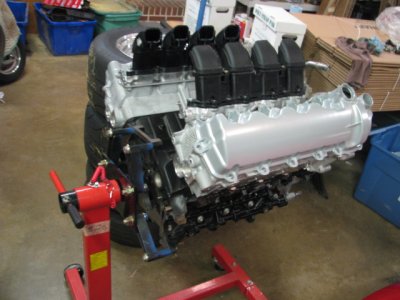
rings are filed. assembly this week. I'm going to use stock ford head gaskets and arp studs. haven't seen anyone with head gasket problems and some of you guys are crazy with boost and stuff so my combo shouldn't have any issues.
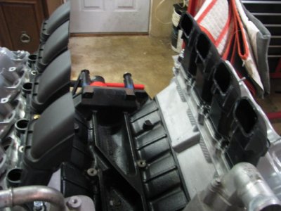
guess I'm going to have to make an intake manifold. I have a friend that does general CNC work. I've cut up a stock intake to get the runners isolated so he can digitize the the lower portion and then I'll figure out the runner length and size so he can make some billet runners also. then we can just weld up a plenum and inlet. I'm going to make the intake fit a 4.6 block first then have him make an offset cmcv delete to fit the 5.4 that way if it works i can reproduce them if needed.
Outstanding!