
Scott
Senior Member
Intake Centerline Method – Degree a 3V Camshaft
To get ready, I pulled the timing chains off and removed the cams to insert a Trick Flow Specialties Solid Lash Adjuster on one of the intake valves for cylinder #1 and #6. Reinstalled the camshafts and timing components and although I did not rotate the crankshaft felt it would be prudent to go through the process of locating TDC again. Once TDC was located I inserted one of the modified Roller Followers to coincide with the cylinder # 1 TFS Solid Lash Adjuster. Next the Lash Adjuster Allen set screw was threaded in (to push the top portion of the Lash Adjuster away from the bottom portion) to achieve zero lash.
Based on the Comp Cam instructions I purchased their Crankshaft Socket part number 4798 because I liked that it provided the ability to adjust the degree wheel without the risk of moving the crankshaft. It worked fine in locating TDC, but once I had a roller follower installed and experienced the additional resistance of a valve spring it was evident that the socket inside diameter was too big and sloppy on the 3V crankshaft. This resulted in a couple of degrees of “jerk” when you changed the direction of the crankshaft rotation. I sent of a quick note to Comp Cams Tech Support and got a prompt answer – you have the wrong socket for the 3V you need part number 4793. Fortunately I was able to locate one locally overnight. The new socket is a perfect fit and eliminated the “jerk” when changing the direction of crankshaft rotation. Hopefully Comp Cams will correct their 3V Cam Install documentation very soon!
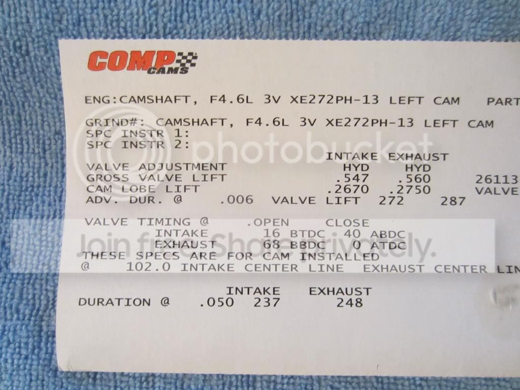
Comp Cam specifications are for a cams installed at a 102.0 intake center line.
In summary I went through the process detailed below for both cylinder # 1 and #6 and in both cases obtained the same results measuring an intake centerline of 103.25 degrees. The following pictures illustrate cylinder # 1
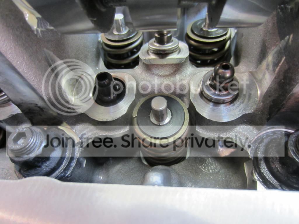
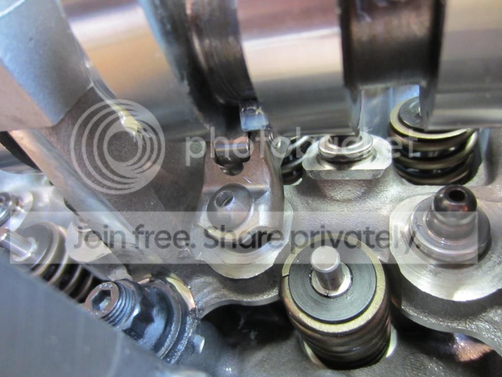
TFS Solid Lash Adjuster installed at cylinder #1 intake valve.
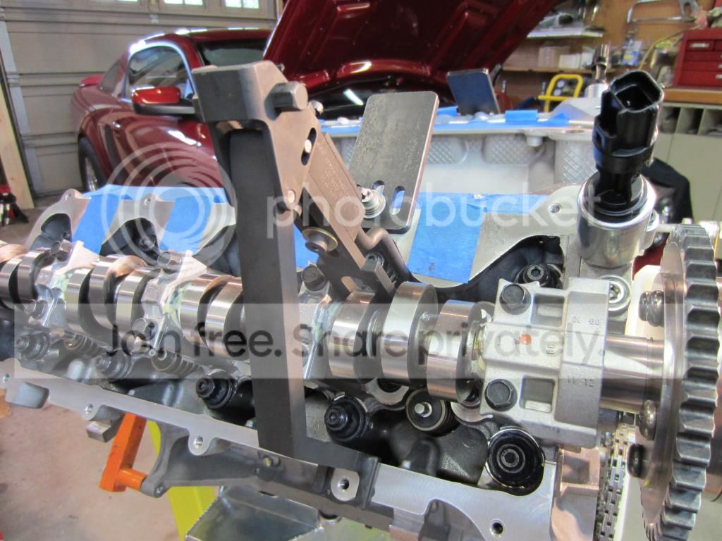
Modified Roller Follower Installed at cylinder #1 intake valve with the Freedom Racing Spring Compressor Tool
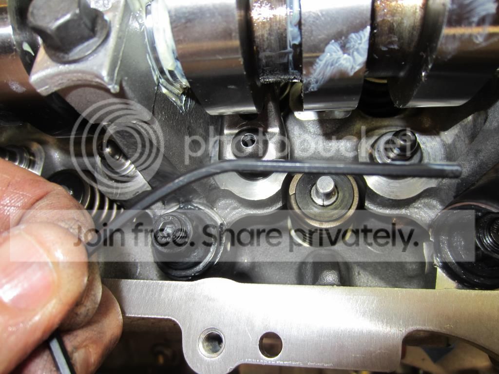
TFS Solid Lash Adjuster was set to zero lash using a “custom modified” (bent) 3/32” Allen Key to maneuver by the camshaft lobe.
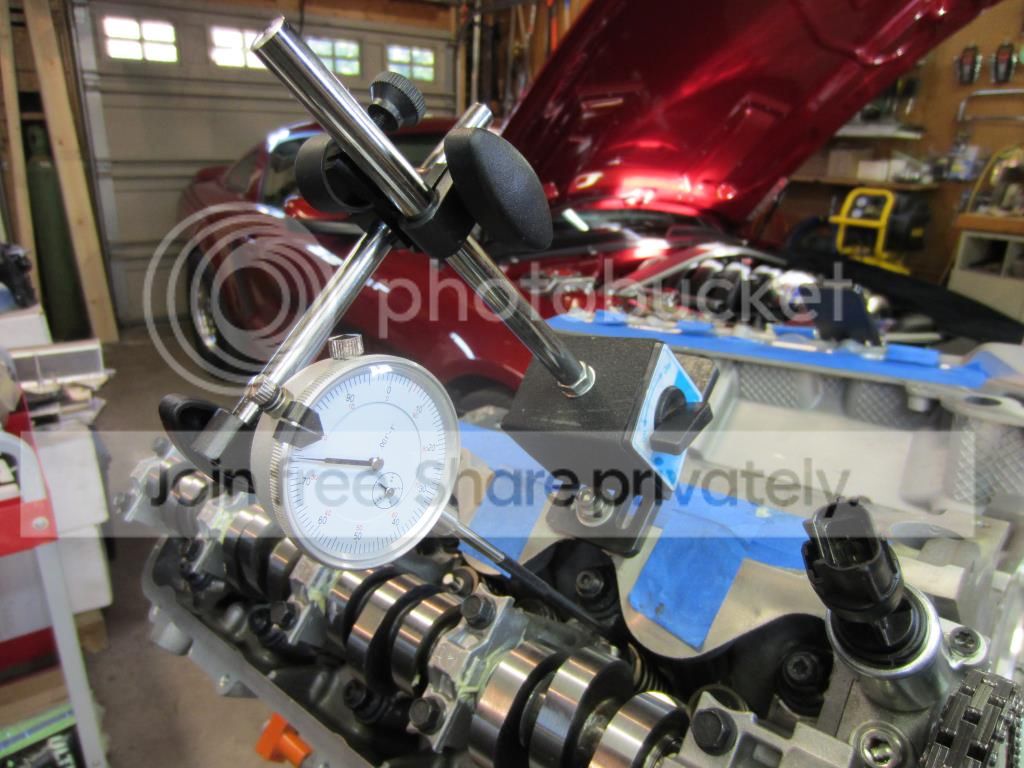
A Dial Indicator Mount was securely fixed to a valve cover bolt hole at cylinder # 1 and the Dial Indicator was adjusted so that the tip of the indicator plunger/extension would contact the retainer of the intake valve. Not to introduce any geometric errors care was taken to ensure the plunger was parallel to the valve stem.
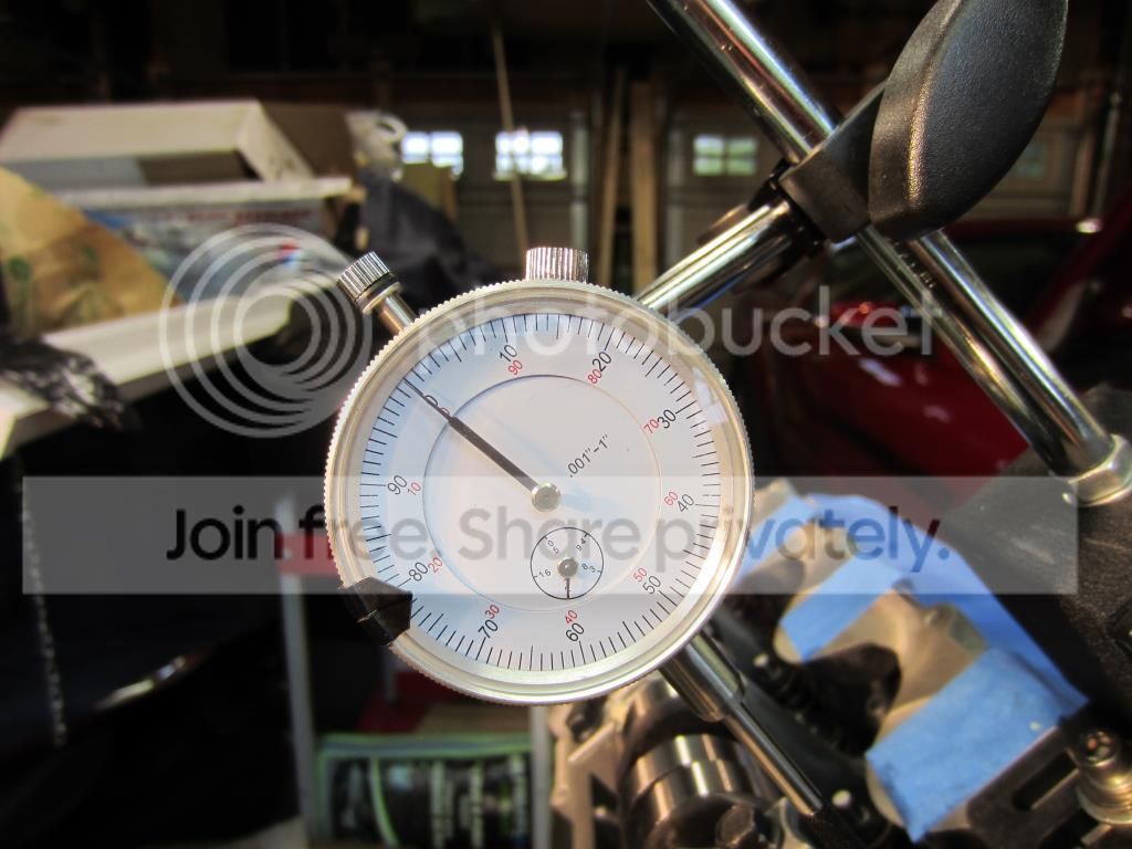
Crankshaft was rotated clockwise until the camshaft reached maximum intake lift. At maximum lift the Dial indicator begins to change direction. The Dial Indicator was set to zero at this point.
The crankshaft was slowly rotated counter clockwise until the dial indicator read .100”. Then the crankshaft was rotated clockwise again until the dial indicator read .050” before maximum lift. In my case the degree wheel reading was 69 degrees “A”.
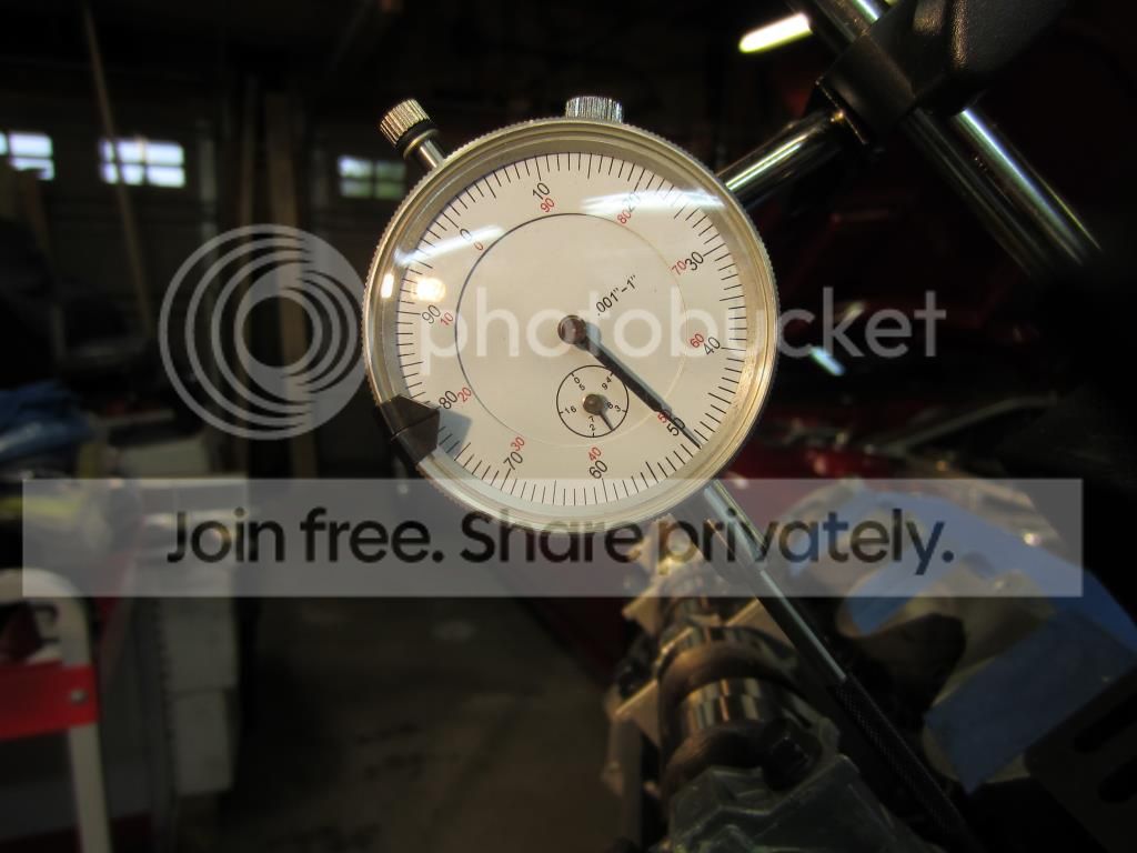
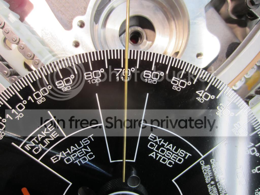
Rotation of the crankshaft was continued clockwise past zero to .050” on the intake closing side of maximum lift. In my case the degree wheel reading was 137.5 degrees “B”.
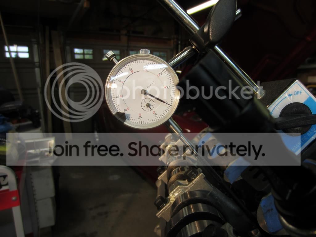
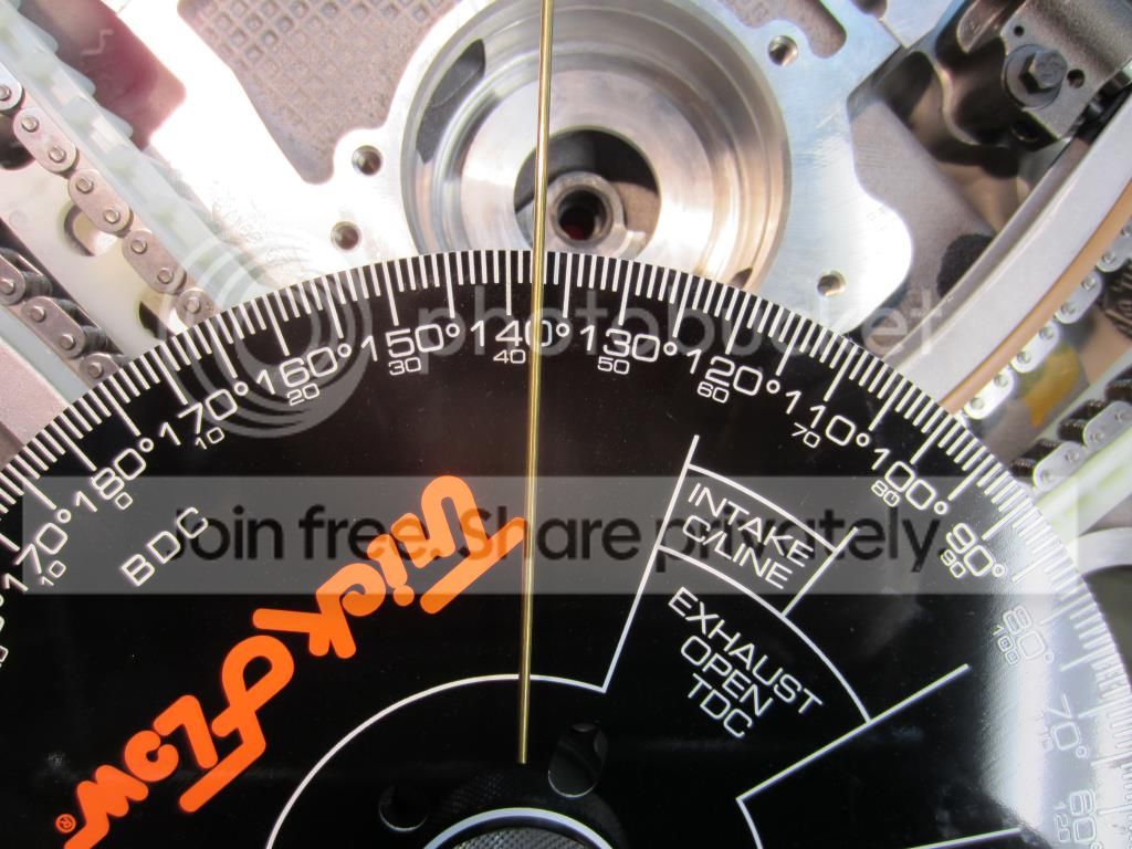
“A” 69 and “B” 137.5 added together (69 + 137.5 = 206.5) and divided by 2 gives me the actual intake centerline “C” (206.5 / 2 = 103.25).
Since the TFS Modular Ford Adjustable Crank Gears I have are only adjustable in +/- increments of 2 degrees up to 8 degrees and my camshaft centerline measures out to 103.25 giving a 1.25 difference (103.25 – 102.0).
Your input would be appreciated on how to make a 1.25 centerline adjustment?
To get ready, I pulled the timing chains off and removed the cams to insert a Trick Flow Specialties Solid Lash Adjuster on one of the intake valves for cylinder #1 and #6. Reinstalled the camshafts and timing components and although I did not rotate the crankshaft felt it would be prudent to go through the process of locating TDC again. Once TDC was located I inserted one of the modified Roller Followers to coincide with the cylinder # 1 TFS Solid Lash Adjuster. Next the Lash Adjuster Allen set screw was threaded in (to push the top portion of the Lash Adjuster away from the bottom portion) to achieve zero lash.
Based on the Comp Cam instructions I purchased their Crankshaft Socket part number 4798 because I liked that it provided the ability to adjust the degree wheel without the risk of moving the crankshaft. It worked fine in locating TDC, but once I had a roller follower installed and experienced the additional resistance of a valve spring it was evident that the socket inside diameter was too big and sloppy on the 3V crankshaft. This resulted in a couple of degrees of “jerk” when you changed the direction of the crankshaft rotation. I sent of a quick note to Comp Cams Tech Support and got a prompt answer – you have the wrong socket for the 3V you need part number 4793. Fortunately I was able to locate one locally overnight. The new socket is a perfect fit and eliminated the “jerk” when changing the direction of crankshaft rotation. Hopefully Comp Cams will correct their 3V Cam Install documentation very soon!
Comp Cam specifications are for a cams installed at a 102.0 intake center line.

In summary I went through the process detailed below for both cylinder # 1 and #6 and in both cases obtained the same results measuring an intake centerline of 103.25 degrees. The following pictures illustrate cylinder # 1
TFS Solid Lash Adjuster installed at cylinder #1 intake valve.

Modified Roller Follower Installed at cylinder #1 intake valve with the Freedom Racing Spring Compressor Tool


TFS Solid Lash Adjuster was set to zero lash using a “custom modified” (bent) 3/32” Allen Key to maneuver by the camshaft lobe.

A Dial Indicator Mount was securely fixed to a valve cover bolt hole at cylinder # 1 and the Dial Indicator was adjusted so that the tip of the indicator plunger/extension would contact the retainer of the intake valve. Not to introduce any geometric errors care was taken to ensure the plunger was parallel to the valve stem.

Crankshaft was rotated clockwise until the camshaft reached maximum intake lift. At maximum lift the Dial indicator begins to change direction. The Dial Indicator was set to zero at this point.

The crankshaft was slowly rotated counter clockwise until the dial indicator read .100”. Then the crankshaft was rotated clockwise again until the dial indicator read .050” before maximum lift. In my case the degree wheel reading was 69 degrees “A”.


Rotation of the crankshaft was continued clockwise past zero to .050” on the intake closing side of maximum lift. In my case the degree wheel reading was 137.5 degrees “B”.


“A” 69 and “B” 137.5 added together (69 + 137.5 = 206.5) and divided by 2 gives me the actual intake centerline “C” (206.5 / 2 = 103.25).
Since the TFS Modular Ford Adjustable Crank Gears I have are only adjustable in +/- increments of 2 degrees up to 8 degrees and my camshaft centerline measures out to 103.25 giving a 1.25 difference (103.25 – 102.0).
Your input would be appreciated on how to make a 1.25 centerline adjustment?