I'm going to double check on Monday and find out what JPC recommends as far as the studs. It has been one of my biggest concerns which is why I originally wanted to go with the TTY head bolts but I already overbuilt the engine so the ARP studs are nice.
They are Darton Hat style sleeves, Diamond Pistons, (-5 cc dish I'm pretty sure, but I have to find that out anyway so I will confirm), Manley lightweight I beam rods, Total Seal Rings, King HP main bearings I think and Clevite Rod bearings.
My bad, I could have sworn I got back to you! Yes sir, keeping it N/A for now. I feel that I can go less overboard with things this way. If I slapped a turbo on it I know I would have tried to push it and would have probably gone stupid with the car and didn't want to do that.
Also ....I'm not certain which instructions I should use. I think I'm going to go with 4.6L 4V becauz fucking termi is the fucking greatest engine ever!!! According to the Cobro's.
So I talked to Tim Eichhorn at MPR Engines in Flordia yesterday and he advised me that they got the billet secondary timing chains in. Finally, the last piece that I was waiting for will be here sometime today supposedly *fingers crossed*. I know I am overbuilding the engine as is in hopes that it will not break on me. That being said, I chose to go with the Billet chains over the Ford units due to the Trick Flow valve springs in the engine having a higher seat pressure than the stock Boss springs (which for as decent as they are, they really aren't that great of valve springs), couple that with the aftermarket cams and the RPM’s that I will be turning and it seemed like a good choice. All along this engine was built to sustain the high RPM’s that I would see while doing some HPDE days and autocrossing at the expense of low and some mid range power which I am fine with due to the 3.73’s it shouldn’t feel like an absolute pig in those power ranges.
I ran home during lunch and started breaking down the motor as I wanted to start from the beginning in case I forgot something, so I tore the block down and took the heads off the block. I started with putting the oil pump pickup tube spacer on, followed by the pickup tube and windage tray followed by the oil pan.
I also turned my attention to the oil pump now and torquing down those bolts. The oil pump has some unique steps to it so be sure to follow the torque sequences for each bolt. See the picture for reference.
Well, today was a productive day despite some setbacks from my stupidity. First let me start off by saying that despite what the service manual says, don't put the oil pan on first. That should be the last thing to go on this way you can ensure that the balancer is installed correctly. Thanks to Eric @ JPC Racing for pointing that out to me when I asked a completely unrelated question.
That being said, let's start off.
Yesterday I got the secondary chains from MPR Racing Engines in Florida. I have to say thank you to Tim and Christina for getting these out ASAP for me and letting me know that they received them the second they came in.
Last night I got the rear main seal plate put on the back of the motor. Using Permatex Anerobic Gasket Maker. I put a bead of this on the motor .According to the service manual, you put the bead on the motor, not on the retainer plate itself. I don't have a picture of this as it was night and I just wanted to get inside and shut it down for the night but the rear main seal is on.
Note: When putting this on, use a continuos bead of gasket maker and do not move the plate sideways when placing the plate on or as per the manual, you stand a greater chance at having the gasket leak. That would be a giant pain in the ass considering the location of the plate.
Parts list
Retainer Plate - BR3Z-6K301-A
Retainer Plate Bolts - W714962-SXXXXXX (I don't have the last part of the Part number for the bolts.
I just want to say, sorry for all of the typos, I am writing this on my Ipad since my laptop broke last January and I don't have the money to go and get a new one just yet. The next thing I did was turn my attention to the heads. As you may know, the Boss heads were no good. They could have been repaired but I felt it was better to pursue a different path with the heads. The problem with the Boss heads is that there really isn't a lot of machining that can really be done to them compared to the GT heads. There just isn't enough meat on the heads where you can do a good head job. Outside of that the Boss heads are very good for stock heads and flow excellently and are capable of creating some very good power numbers as is. That being said, I talked to Steve over at Tasca and he hooked me up with a set of 2015 GT heads and off they went to RGR for their stage 2 head job. Sometimes it is nice to know what kind of product you are getting
Well, in the meantime I bought a whole bunch of FRPP parts to hurry along the build. Some of these parts JUST came out and Steve didn't even have pricing on some of them just yet but they are as follows:
Coyote Camshaft Drive kit - M-6004-A504 - Includes new Primary and Secondary phasers, Boss 302 Primary tensioners, secondary tensioners, primary chains, secondary chains, oil pump bolts, tensioner pins, tensioner arms, camshaft filters, crank sprocket, tensioner hardware, and camshaft bolts
Coyote Engine Harness kit - M-12508-M50 - Supposedly with this kit there is no rewiring needed for switching to the Cobra Jet Intakes and throttle bodies. We will see how well that claim is. That being said you need the following VCT actuators for this kit.
The 2015 heads come bare with just valves, valve springs, and keepers so I also needed to get some roller followers along with the lash adjusters. I had the heads shipped to me and got them all ready to be put in. I have to say they are a work of art IMO. Trick Flow Valve Springs, RGR bronze valve guides Ferrea oversized valves, and a nice port work to the intake and exhaust ports along with some bowl work and a whole slew of things I am probably forgetting.
That being said, there have been people noticing that their Cobra jet Intake Manifolds intake runners were much larger in size than the intake ports are on the heads. That will cause a little bit of loss in power than if the ports were matched in size.So I took some painters tape and grabbed my x-acto knife and traced the intake ports on the manifold and transferred that over to some cardboard. Well would you look at that
Perfect fit! Don't mind me holding the piece on the head, if I had let it go, it would have fallen down the intake port and I really didn't want that to happen.
From this point I wanted to calculate my compression ratio so I needed to know the combustion chamber volume so I grabbed the tools needed (sorry no pictures of this). You need your spark plug as the spark plug takes up a specific volume in the combustion chamber, a piece of plexiglass with a hole cut in the center, some sort of way to measure the liquid going into the Combustion chamber (a syringe works as it has a marked volume on it), some vaseline and some water. The first thing that I did was to level the head so I grabbed a bunch of coffee filters I use to clean parts and folded them up until I got the heads nice and level. What you are doing is taking your water and filling up the combustion chamber with a specified CC's of water. The factory size is 54.5cc's so when you get to this point you take some vaseline and put it around the combustion chamber to seal the chamber off, now take your piece of plexiglass and put it over the combustion chamber. From there you can continue putting water in the combustion chamber. When you start to get to the top of the piece of plexiglass, you stop. Subtract what you have left in the syringe from the volume of the syringe and add up how many times you added water into the combustion chamber ie. if you have a 10ml syringe (although mine was .5ml URGH) and you filled it 5 times and you have 4 ml's of water left in the syringe you have a combustion chamber size of 56 cc's.
Now that I know this I can go ahead and calculate my compression ratio. While there are calculators out there that will do the math for me, I like to do this sort of stuff so I sat down with a pad and pencil and went about calculating the compression ratio myself. While there are a certain number of ways to calculate your compression ratio, I decided use a technique called slicing pi as it seemed the simplest and easiest way to do this.
Bare with me as we are about to embark on a treacherous journey into the world of ...... MATH
When calculating your compression ratio there are 5 variables that we are going to need to find and we are going to need to solve for. In looking at the ways to find your compression ratio I saw this video and it stood out to me as the most detailed and concise way to find your compression ratio. Beware though, it is 20 minutes long but it is very thorough in the explanation. I have also found a love for Jafromobile and his videos now because of this.
Anyway, snap back to reality and math!! Ok, so the variables that we need to solve are as follows:
V1 = Swept volume - Here you are calculating the engine volume based on the bore and stroke of the cylinder.
V2 = Gasket volume
V3 = Piston to deck volume - Here you are calculating the distance between the piston at top dead center and the deck
V4 = Piston volume
V5 = Head combustion chamber volume
Getting my measurements
I know what my bore is based on the proposed measurements brought forth by RGR & JPC. I don't have a dial bore gauge to calculate my actual bore but when I measured it with my dial caliper at the top (I know this is entirely wrong and un scientific but I didn't have the right tools available to me at the time) it measured out 5 times to an average of 3.699 in, so I am confident in their measurements on stroke as well which I know is 3.800.
In order to find the crushed gasket thickness of the gasket I am using I contacted Cometic and asked them for the crushed measurement and they said that it will be .040 as listed on the packaging and all of the crushed thickness' will be listed on the gaskets so my gaskets crushed thickness is .040.
In order to measure my PTD clearance I had to find TDC on the number 1 piston. Out came my dial indicator and stand that I got with the Comp Coyote Camshaft Degree Kit. Unfortunately, I didn't have anyway to securely fasten it to the deck so I had to hold it steady by hand. Not an easy task to do when you are trying to rotate the engine at the same time. Anyway, it ended up taking me about an hour to find TDC and then I spent another 45 minutes making sure that it was true TDC which ended up with me double checking my measurements 8 times. So, I set TDC and grabbed my smallest feeler gauge and went all the way around the entire piston and couldn't get it threw so I knew the gap was at least .004" I checked with Eric over at JPC about this and he said that Rich makes sure he zero decked the engine. Considering I couldn't get a .005 feeler gauge in there nor could I see daylight between th piston and my straight edge I am pretty confident that is the case.
My pistons are a flat top piston with a .70 valve relief cut in them.
Head CC volume using the method outlined above is 57cc's
Shall we get started on the math now?
Now, according to the Hot Rod magazine article listed below the formula for calculating your compression ratio is as follows
Compression Ratio = (V1+V2+V3+V4+V5) / (V2+V3+V4+V5)
When figuring out the swept volume (displacement in the Hot Rod article), gasket volume, & the piston to deck volume most people will have you follow a formula that looks like this:
(bore/2)^2 x 3.14 (pi) x your variable
Instead of doing that, we are going to be slicing Pi which will divide the circle into 4 equal parts so our equations become MUCH simpler IMO. When we slice pi we come with the number that we multiply everything by .7854
V1
Bore x Bore x Stroke x .7854 = V1
3.700 x 3.700 x 3.800 x .7854 = 40.8580788
V1 = 40.8580788
V2
This one is a little bit tricky. The online calculators seem to use bore of the cylinder rather than the gasket bore size. Using two different measurements will come up with two different compression ratios off by a couple hundredths so I will use the way the online calculators measure gasket volume.
Bore x Bore x compressed gasket thickness x .7854 = V2
3.700 x 3.700 x .040 x .7854 = .43008504
V2 = .43008504
V3
Note: Negative value if the piston protrudes above the deck surface, positive if it is below the deck surface
Bore x Bore x Pistons Distance relative to the deck surface x .7854 = V3
3.700 x 3.700 x .000 x. 7854 = 0
V3 = 0
V4
Because this measurement is in cubic centimeters and we want it to be in cubic inches like the rest of our measurements, we have to multiply this number by .0610237
Because this measurement is in cubic centimeters and we want it to be in cubic inches like the rest of our measurements, we have to multiply this number by .0610237
Now that we have all of our variables, we can go ahead and plug them into our formula above
Compression Ratio = (V1+V2+V3+V4+V5) / (V2+V3+V4+V5)
Compression Ratio = (40.8580788+.43008504+0+.04271659+.4783509) / (.43008504+0+.04271659+.4783509)
Compression Ratio = 44.80923133 / 3.95115253
Compression Ratio = 11.3408001816624
Compression Ratio = 11.34:1
From here we can easily find out our displacement. All we have to do is take V1 (our swept volume of a cylinder) and multiply it by how many cylinders the engine has.
Displacement = V1 x number of cylinders
Displacement = 40.8580788 X 8
Displacement = 326.8646304
Displacement = 327 CI ......... rounded up, always looking for that extra inch right fellas haha
I certainly would have liked to go higher on the compression ratio but stock compression works for me for now. This way I can see what the extra cubic inches and full bolt ons will yield with a Coyote and I'm excited to see what it can do. I know that a Coyote with some big cams can make 577 HP on E85 with 318 CI and a similar setup so I am curious what my entirely different cams and stock compression will do with an extra 9 cubic inches. Plus, down the road when the engine needs to be refreshed I can go a little bit stupid and maybe get that 344ci coyote and run a 12:1 compression ratio and hurt some feelings with it MUWHAHAHAHAHA. I think I will leave this one off here for now.
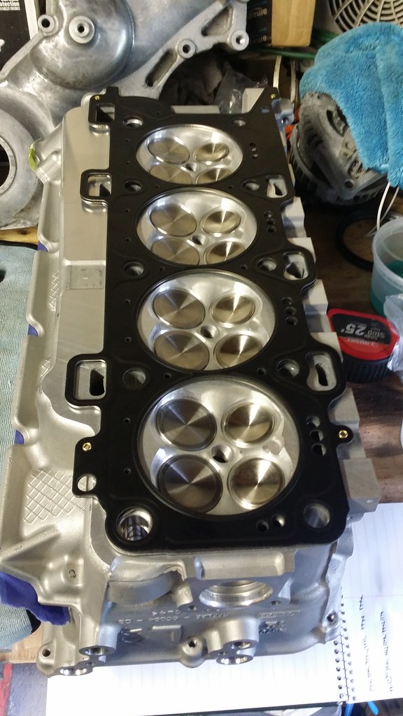
Back to the fun stuff. After I turned my attention away from math and back on putting parts on the car, I put all of the ARP studs back in. I went down to the bottom of the holes because if I turned them half a turn, they were wobbly as shit and it wasn't something I was confident in. Studs went back in the engine and out came the Cometic head gaskets for a 11-14 Mustang. After lining up the head gaskets on the heads, it looks like everything lined up and is all set. So in case anyone is wondering. 2015 heads fit on the 11-14 block and with 11-14 head gaskets without issues.
Head gaskets got put on the deck and then the heads got put onto the block followed by the ARP washers and ARP nuts. As per ARP instructions I used the ARP assembly lube and put some on the threads of the studs as well as the nuts. It may have been overkill but oh well. I asked around bout the torque procedure at Tim Eichhorn over at MPR Racing Engines told me what he uses for the ARP bolts.
Parts List
2015 Heads - FR3Z-6049-A
2015 Heads - FR3Z-6049-B
Cometic 94mm Bore MLS .040" Gasket Right - C5286-040
Cometic 94mm Bore LMS .040" Gasket Left - C5287-040
ARP Head Studs 11-12 Block - 256-4702
Torque Specs
Step 1 - Hand tight
Step 2 - 30lb-ft - I waited an hour before continuing on


 for realz!